Table of Contents
Advertisement
Quick Links
45 Class
2-cycle engine
70 Class
4-cycle engine
INSTRUCTION MANUAL / Montageanleitung
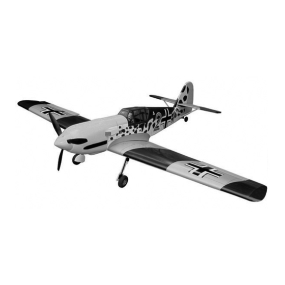
TECHNISCHE DATEN
Spannweiter
Lange
Elektroantrieb
Verbrennerantrieb
Fernsteuerung
WARNING! This radio controlled model is NOT a toy. If modified or flown carelessly it could go out of controll and
cause serious human injury or property damage. Before flying your airplane, ensure the air field is spacious enough.
Always fly it outdoors in safe areas and seek professional advice if you are unexperienced.
ACHTUNG! Dieses ferngesteuerte Modell ist KEIN Spielzeug! Es ist für fortgeschrittene Modellflugpiloten bestimmt,
die ausreichende Erfahrung im Umgang mit derartigen Modellen besitzen Bei unsachgemäßer Verwendung kann
hoher Personen- und/oder Sachschaden entstehen. Fragen Sie in einem Modellbauverein in Ihrer Nähe um
professionelle Unterstützung, wenn Sie Hilfe im Bau und Betrieb benötigen. Der Zusammenbau dieses Modells ist
durch die vielen Abbildungen selbsterklärend und ist für fortgeschrittene, erfahrene Modellbauer bestimmt.
1560mm
1120mm
G-46 HP Motor
7.5cc 2-T / 8.5cc 4-T
5 Kanal / 5 Servos
SPECIFICATIONS
Wingspan
Length
Electric Motor
Glow Engine
7.5cc 2-T / 8.5cc 4-T
Radio
5 Channel / 5 Servos
1560mm
1120mm
G-46 HP Motor
Advertisement
Table of Contents

Related Manuals for VQ Models MESSERSCHMITT BF-109


Summary of Contents for VQ Models MESSERSCHMITT BF-109
- Page 1 45 Class 2-cycle engine 70 Class 4-cycle engine INSTRUCTION MANUAL / Montageanleitung SPECIFICATIONS TECHNISCHE DATEN Wingspan 1560mm Spannweiter 1560mm Length 1120mm Lange 1120mm Electric Motor G-46 HP Motor Elektroantrieb G-46 HP Motor Glow Engine 7.5cc 2-T / 8.5cc 4-T Verbrennerantrieb 7.5cc 2-T / 8.5cc 4-T Radio 5 Channel / 5 Servos...
- Page 2 REQUIRED FOR OPERATION (Purchase separately) 10.5x6 for .40 - 2 cycle engine Extension for aileron 11x6 for .46 - 2 cycle engine servo, retract servo. 12x6 for .60 - 4 cycle engine 12x7 for .70 - 4 cycle engine 13x7 - 13x8 for Electric Motor Motor Control Retract landing gear VQAR02...
-
Page 3: Joining The Wing
1-Aileron extension cord installation 30cm Extension cord Thread (pre-installed at factory) WING BOTTOM-VIEW Using the thread (pre-installed at factory) to slide the aileron extension cord into the wing half. Using the adhesive tape to secure the one end of the aileron extension cord in place. - Page 4 3- Joinning the wing Glue WING TOP-VIEW Wing joiner Wing half Glue must go inside ! Make sure to glue securely, If not properly glued, a failure in flight may occur. 30 min. Epoxy Carefully slide the wing halves together, ensuring that they are accurately aligned.
- Page 5 5- Retract servo mount Retract servo tray Note: Retract servo mount “B”is taller than “C” Retract servo mount CENTER WING SECTION TOP-VIEW BOTTOM 6- Retract servo Install the retract servo onto the retract servo mount and secure it in place with four screw (included with radio set).
-
Page 6: Aileron Servo
8- Gear cover installation ..2 .....4 ...2 1/16 WING BOTTOM-VIEW 1.5mm Attach the wheels on the main gear wires(A) with plastic wheel retainers(B) and wheel collars(C) as show. Attach the ABS gear cover(D) on the wires with fitting strap(E) and screws(F) as show. Attach the ABS wheel well cover 9- Fixed gear (for fix gear only), secure them... -
Page 7: Aileron Linkage
11- Aileron linkage -Switch on the radio (trims centered) then mount the ailerons servo horn Plastic control horn in neutral position. -The servo horn should be perpendicular to the servo ..2 ....4 ..2 3mm set Screw Aileron pushrod D=5/64”(2mm) Attach the control horn on the aileron with 2x15mm screws. 2 mm Screw the clevies halfway on the theared end of the aileron push rod. - Page 8 13- Engine 3x20mm screw ...4 Nut..4 6-Reposition the engine on the engine mount beams so the distance from the prop hub to the fire wall is 4-51/64”(122mm). 7-Mark the engine mounting plate where the four holes are to be drilled. 8-Remove the engine and drill 1/8”(3mm) hole through the beam at each of the four marks made above.
-
Page 9: Electric Motor
15- Fuel tank Blow To muffler Water Filler tube Rubber stopper To engine 3x35mm screw Checking for leaks - block the vents and blow into the feed. if in doubt submersing the tank in a blow of water will show up any problems. TOP VIEW Carefully install the fuel tank to ensure that they will not shift during flight (secure the fuel tank in place using foam padding). -
Page 10: Vertical Stabilizer
1-Trial fit the vertical stabilizer in place . Check the alignment of the Vertical Stabilizer vertical stabilizer. When you are satisfied with the alignment, use a pencil to trace around the right and left of the stabilizer where it meets the fuselage. 2-Remove the vertical stabilizer from the fuselage. - Page 11 21- Tail gear Piece of fuel tube (not included) Collar 0.5”~0.6” (12~15mm) 3x12mm screw Horn 0.3”(8mm) 1/16 1.5mm Horn ....1 BOTTOM VIEW 2.2m collar ....1 1/16 1.5mm 3x12mm screw ....2 BOTTOM VIEW 22- Servo NOTE: Place of servos may be change depend of engine (Four-stoke or two-stroke engine) Rudder push rod Rudder servo...
-
Page 12: Cowling Installation
24- Cowling installation 2.5X8mm screw ..4 1/16 1.5mm 2~3mm 5/64 2.5x8mm screw 25- Decor Sticker ABS airs coop 26- Air scoop installation Sticker ABS airs coop ABS air scoop 3”(76mm) 3”(76mm) 1”(25mm) Cut away only the covering Using the ABS air scoop as a template, trace around the outside edge of the ABS air- scoop and then remove it. - Page 13 27- Control surface 15/64” 15/64” AILERON STROKE QUERRUDER 1-3/16” 13/32” 30 mm 10mm 1-3/16” 13/32” 30 mm ELEVATOR STROKE RUDDER STROKE 10mm HÖHENRUDER SEITENRUDER 28- Balance DO NOT try to fly an out-of-balance model ! 3-15/32” ~ 3-41/64” 88 ~ 92 mm Wing center section 29- Decal Sticker...
Need help?
Do you have a question about the MESSERSCHMITT BF-109 and is the answer not in the manual?
Questions and answers