Advertisement
Quick Links
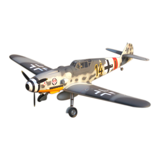
BF-109 50CC
Specification:
Length:
2035mm(80")
Wing span:
2235mm(88")
Wing area:
79.7sq.dm(8.6sq.ft)
Wing loading: 125.5g/sq.dm(41.1oz/sq.ft)
Flying weight: 10kg(22 bs)
Radio:
6ch & 8servos
Engine:
50cc gasoline engine
SAFETY PRECAUTIONS
INSTRUCTION MANUAL
This R/C airplane is not a toy!
(The people under 18 years old is forbidden from flying this model)
First-time builders should seek advice from people having building
experience.If misused or abused,it can cause serious bodily injury
and damage to property.
Fly only in open areas and preferably at a dedicated R/C flying site.
We suggest having a qualified instructor carefully inspect your
airplane before its first flight.Please carefully read and follow all
instructions included with this airplane,your radio control system
and any other components purchased separately.
Advertisement

Related Manuals for VQ Models BF-109 50CC


Summary of Contents for VQ Models BF-109 50CC
- Page 1 BF-109 50CC Specification: Length: 2035mm(80") Wing span: 2235mm(88") Wing area: 79.7sq.dm(8.6sq.ft) Wing loading: 125.5g/sq.dm(41.1oz/sq.ft) Flying weight: 10kg(22 bs) INSTRUCTION MANUAL Radio: 6ch & 8servos Engine: 50cc gasoline engine This R/C airplane is not a toy! (The people under 18 years old is forbidden from flying this model) First-time builders should seek advice from people having building experience.If misused or abused,it can cause serious bodily injury...
- Page 2 Gasoline 6 channel radio for aiplane is highly recommended for this model. : 50cc gas engine Optional parts: rubber wheel with metal hub, oleo struts and retracts system. 5 in Spinner We strongly recommend you use the thread lock for all the screws when you build your model.
- Page 3 Adjustment. Assemble the aileron to main wing with instant type CA glue. Be careful Adjustment. Accessory list for the coming installation steps. to ensure the moving parts of the hinges are able to move freely. Clevis Clevis Collar (3mm) Side View Rod (2.5x300mm) Top view TP Screw (2.3x12mm)
-
Page 4: Accessory List For The Coming Installation Steps
Keep some space about 1mm width between Secure the servo.Install the nylon control horn Accessory list for the coming installation steps. Epoxy the plastic tubes in the holes tightly. trailing edge and flap. and connect the linkage. Wheel (115mm) TP Screw (2.3x12mm) Trailing edge Collar (6mm) - Page 5 Assemble the cockpit to the fuselage and drill holes through the Keep some space about 1mm width between Glue the exhaust to the fuselage as below. ply and the wooden block in the fuselage and the cockpit,then Install the nylon control horn and connect the linkage. trailing edge and flap.
- Page 6 Epoxy wooden block to the relevant position behind the According to the location wooden block drill holes Drill a hole to relevant position in the mid wing marked position and drill holes through the marked point Accessory list for the coming installation steps. in the fuselage.
- Page 7 Drim the relevant position on the cowling for Trim the covering carefully from the relevant position According to the rib template drill holes in one wing and Connect the electric retract & receiver as illustration below. assembling the engine. in the wing for assembling the wheel wells. epoxy wood dowel in them.
- Page 8 Drill four holes at the diameters as show Assemble the wings. Set the U-style wire through the enlarged hole as below. Assemble the throttle servo in the fuselage. for engine mount. Make sure to glue securely. If not properly glued, a failure in flight may occur. U-style wire 130x25mm 6.2mm Securely glue together.If coming off during flights,...
- Page 9 Assembly of the stabilizer. Install the servo. Accessory list for the coming installation steps. Apply instant type CA glue to elevator and pin hinge. Make sure to glue securely. Washer(2x5mm) Pin hinge(24x24mm) Screw (2x10mm) Screw (5mm) If not properly glued, a failure in flight may occur. (Not included) Securely glue together.If coming off during flights, Ball joint...
- Page 10 Epoxy the fibreglass tubes to appropriate position as Assemble the wheel mount to the thick wooden block below and leave some space with width of 1mm between The sketch map after the rudder shaft assemble finished. with screw,cut the surplus parts and epoxy the thinner Connect the elevator and the servo via the steel wire.
Need help?
Do you have a question about the BF-109 50CC and is the answer not in the manual?
Questions and answers