Advertisement
Quick Links
60 Class
2-cycle engine
90 Class
4-cycle engine
Or Electric equivalent
INSTRUCTION MANUAL
MONTAGEANLEITUNG
SPECIFICATIONS
Wingspan
Length
Electric Motor
1000 Watt (BOOST 90)
Glow Engine
Radio
TECHNISCHE DATEN
Spannweiter
Lange
Elektroantrieb
1000 Watt (BOOST 90)
Verbrennerantrieb
Fernsteuerung
WARNING! This radio controlled model is NOT a toy. If modified or flown carelessly it could go out of controll and
cause serious human injury or property damage. Before flying your airplane, ensure the air field is spacious enough.
Always fly it outdoors in safe areas and seek professional advice if you are unexperienced.
ACHTUNG! Dieses ferngesteuerte Modell ist KEIN Spielzeug! Es ist für fortgeschrittene Modellflugpiloten bestimmt,
die ausreichende Erfahrung im Umgang mit derartigen Modellen besitzen Bei unsachgemäßer Verwendung kann
hoher Personen- und/oder Sachschaden entstehen. Fragen Sie in einem Modellbauverein in Ihrer Nähe um
professionelle Unterstützung, wenn Sie Hilfe im Bau und Betrieb benötigen. Der Zusammenbau dieses Modells ist
durch die vielen Abbildungen selbsterklärend und ist für fortgeschrittene, erfahrene Modellbauer bestimmt.
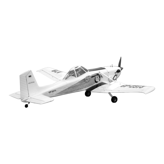
CESSNA 188
SEMI SCALE MODEL
1920mm
1300mm
.60 2-T / .90 4-T
6 Channel / 8 Servos
1920mm
1300mm
10cc 2-T / 15cc 4-T
6 Kanal / 8 Servos
AGWAGON
Advertisement

Related Manuals for VQ Models CESSNA 188 AGWAGON


Summary of Contents for VQ Models CESSNA 188 AGWAGON
- Page 1 60 Class 2-cycle engine CESSNA 188 90 Class 4-cycle engine AGWAGON Or Electric equivalent SEMI SCALE MODEL INSTRUCTION MANUAL MONTAGEANLEITUNG SPECIFICATIONS Wingspan 1920mm Length 1300mm Electric Motor 1000 Watt (BOOST 90) Glow Engine .60 2-T / .90 4-T Radio 6 Channel / 8 Servos TECHNISCHE DATEN Spannweiter 1920mm...
- Page 2 REQUIRED FOR OPERATION (Purchase separately) BENOTIGTE KOMPONENTEN (Nicht im Lieferumfang enthalten) 70mm Spinner Extension cord Servoverlangerungskabel Brushless Motor Minimum 6 channel radio PICHLER BOOST 90 for airplane Brushless ESC Minimum 6 Kanal Brushless Regler Fernsteuerung Battery / Flugakku LEMONRC 5300-22.2V .60 cu.in.
- Page 3 Trial fit the horizontal stabilizer in place on the 1- Horizontal Stabilizer / Hohenruder fuselage. Check the alignment of the horizontal stabilizer by measuring from a fixed point along the center line of the fuselage to the leading edge on each side of the horizontal stabilizer. The distance must be equal on both sides.
- Page 4 4- Tail wheel leg / Spornradtrager 3x12mm screw ...4 Test-fit the rudder torque rod into the slot. NOTE: You may need to open up the slots so that the torque rod bearing are not too difficult to push in Tail wheel control arm Tail wheel push-rod Rudder torque rod 1- Insert the tail wheel pushrod into the hole on the tail wheel control arm (as show).
- Page 5 6- Main landing gear / Fahrwerk 4X15mm screw Aluminum landing gear 4x15mm screw Aluminum Haupfahrwerk ...6 Note: All holes on the fuselage and bilnd-nuts are pre-installed at factory. 7- Wheel / Radl 4X30mm screw ..2 ....2 ....2 .....2 8- Engine mount / Motortrager ! Align the mark on both mounts 4X25mm screw with the mark on the fuselage...
-
Page 6: Servo Installation
9- Engine / Motor 140-141mm TOP-VIEW 140 - 141mm ! Engine thrust on balk head is already adjust at factory 10- Servo installation Switch Rudder servo Nylon pushrod guide Throttle servo Nylon pushrod guider TOP VIEW / Draufsicht 11- Linkage / Alenkungen BOTTOM - VIEW / Unteransicht ..2 2x20mm... - Page 7 SIDE-VIEW / Seitenansicht 12- Fuel tank / Kraftstofftank FUEL TANK RECEIVER BATTERY 13- Cowling / Motorhaube 2.5x10mm..4 Ruler Attach the board or transparent plastic on the side of the fuselage with the adhesive tape as show. Using a pencil or felt tipped pen trace around the engine head where it meet the cowl. Cut the opening the board or trans- parent plastic for the engine head as marked above.
- Page 8 14- Li-po battery / Li-po akku IN CASE OF LI-PO BATTERY USING Slide the battery stand throughout the slots on the bottom of F3 One end of the battery stand touched the rear of the fire-wall FUEL TANK IN CASE OF GLOW ENGINE USING Magnetic Battery stopper (3mm plywood) FUEL TANK STAND...
- Page 9 15- Servo BOTTOM - VIEW / Unteransicht 2x10mm Flap servo hatch screw (plywood) Flap push rod exit Aileron servo Aileron push rod 16- ABS Shield 1-Using the ABS shield as a template, trace around the outside edge of the ABS air-scoop,and then remove it. 2-Using a sharp hobby knife, cut away the covering inside the lines.
- Page 10 18- Wing installation / Flachenbefestigung 5X20mm screw ..2 1- Test-fit the dowel into the hole....2 2- Secure the dowel in place using CA glue. Do the same way with another haft wing. Wood dowel Wood dowell 5x20mm screw 5mm washer Lightly, push the half wing to the side of fuselage.
-
Page 11: Cockpit Installation
20- Cockpit Black nylon tube 21- Canopy / Kabinenhaube 2x12mm screw ...5 2x12mm screw 22- Cockpit installation 3X15mm screw ...2 3x15mm screw... - Page 12 23- Wing brace 3x15mm ..2 24- Tail shield Fiberglass shield...
- Page 13 25- Tail shield 3x10mm screw ...4 3x10mm screw 26- Control surface & Balance Adjust the travel of each control surface to the values Schwerpunkt & Ruderausschlage in the diagrams these values fit general flight capabilites. Readjust according to your needs and flight level. Position for right diagram(CG) 12mm...
Need help?
Do you have a question about the CESSNA 188 AGWAGON and is the answer not in the manual?
Questions and answers