IDTECK Star 100R Quick Installation Manual
Standalone controller
Hide thumbs
Also See for Star 100R:
- User manual (40 pages) ,
- Manual (71 pages) ,
- Quick installation manual (21 pages)
Table of Contents
Advertisement
Quick Links
Advertisement
Table of Contents

Related Manuals for IDTECK Star 100R


Summary of Contents for IDTECK Star 100R
- Page 1 Quick Installation Guide...
-
Page 2: Important Safety Instructions
- If liquid has been spilled on the product, unplug it and contact nearest service center. Cautions about Cleaning - Do not clean the product with water. Clean gently with dry cloth or tower - Do not use chemicals such as benzene, thinner or acetone for cleaning. Jun. 2011 Copyright © IDTECK Co., Ltd. -
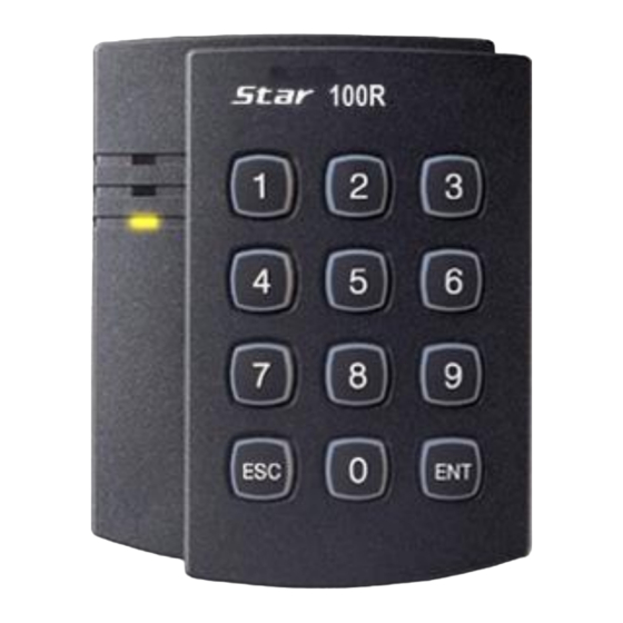
Page 3: Identifying Supplied Parts
Wall Mount O-Ring User’s Manual (1ea) (1ea) (5ea) (1copy) 3.5*40 Screw 3.5*12 Screw Anchor Bolt Cable & Diode Master Card (4ea) (4ea) (4ea) (1ea) Cable(4 ea), Diode(2 ea) 3.FRONT PANEL DESCRIPTION Figure: Front Panel Jun. 2011 Copyright © IDTECK Co., Ltd. -
Page 4: Installation
2. Using 2 screws, install wall mount to the wall. ※CAUTIONS Before mounting the STAR 100R unit to the Wall Mount bracket, operational testing of the unit should be completed, as the locking pins will lock the unit to the Wall Mount. Removing the unit from the Wall Mount bracket after they have been installed together may cause damages to the bracket and render its effectiveness. -
Page 5: Wiring Color Table
Brown with White Stripe Aux Input 3 INPUT3 Green with Red Stripe RESERVED Blue with Red Stripe RESERVED Yellow with White Stripe 3PIN (CON2) RS232-TX Black with White Stripe RS232-RX Red with White Stripe Ground Black Jun. 2011 Copyright © IDTECK Co., Ltd. - Page 6 TTL Output wire is changed to Wiegand Data 0 Output, you can’t initialize the 100W/IP100W using the wires. (You can use those functions again when setting SW1 and SW2 to the default state.) Jun. 2011 Copyright © IDTECK Co., Ltd.
-
Page 7: System Wiring For Typical Application
- Connect (-) wire of Door Lock to Power GND (-) wire. 6.2.2 Connection of POWER FAIL SECURE: Door Lock - Connect Door RELAY (COM), Grey with Red stripe wire to DC +12V (be sure that the existing Jun. 2011 Copyright © IDTECK Co., Ltd. -
Page 8: Alarm Device Connection
- Connect Telephone Line plug (RJ-14) to Auto-Dialer. (If an active High Auto-Dialer is used, then see section 12-59 of the main manual to change the TTL output level from the defaulted setting.) Jun. 2011 Copyright © IDTECK Co., Ltd. -
Page 9: Rs-232 Communication Port Connection
- Connect (-) wire of Chime Bell unit to Power GND (-) wire. 7. INITIAL SETUP The Flash memory of each shipped STAR 100R contains a minimum set of defaulted values, but it does not have any other preprogrammed values or user’s data in it, therefore, Initial Setup is required upon the first time the unit is powered-up in order to operate the unit properly. - Page 10 (4) The first 4~6 digit PIN becomes the Configuration PIN and the subsequent 4~6 digit PINs are registered as User Access PINs. Once all User Access PINs have been registered, enter the Configuration PIN again to complete the registration. (Please store the Configuration PIN for future changes.) Jun. 2011 Copyright © IDTECK Co., Ltd.
- Page 11 (10) Delay time to activate SECURE MODE = 00 min. (11) Door Open time-out for Door Contact sensor = 00 sec. (12) Number of times of Try-out = 05 times (13) Input keypress time-out time = 20 sec. Jun. 2011 Copyright © IDTECK Co., Ltd.
-
Page 12: Operation
8.5. Secure Mode The last person to exit can change the operation of the unit from Normal Mode to Secure Mode by entering the Secure Code of onto the keypad. Change to Secure Mode. Jun. 2011 Copyright © IDTECK Co., Ltd. - Page 13 See section 9.7 and 12.29 of the main manual for more instructions on this feature. 8.7. Chime Bell Operation key can be used to activate an external Chime Bell for 5 seconds, the defaulted value. Jun. 2011 Copyright © IDTECK Co., Ltd.
- Page 14 5) Disconnect orange wire and orange with white stripe wire as shown above (normal connection diagram) and power on. 100R: Over V5.0.4 / IP100R: Over V2.0.2 4) Disconnect those two wires and wire them as shown above (normal connection diagram). Jun. 2011 Copyright © IDTECK Co., Ltd.
- Page 15 Quick Installation Guide 10. Template Jun. 2011 Copyright © IDTECK Co., Ltd.
Need help?
Do you have a question about the Star 100R and is the answer not in the manual?
Questions and answers