IDTECK Star 100R User Manual
Hide thumbs
Also See for Star 100R:
- Quick installation manual (16 pages) ,
- Manual (71 pages) ,
- Quick installation manual (21 pages)
Table of Contents
Advertisement
Advertisement
Table of Contents

Related Manuals for IDTECK Star 100R


Summary of Contents for IDTECK Star 100R
- Page 1 User’s Manual...
-
Page 2: Table Of Contents
Table of Contents 1. Important Safety Instructions ................3 2. General ......................4 3. Features ......................4 4. Specification ..................... 5 5. Front Panel Description ................... 5 6. Identifying Supplied Parts ................6 7. Installation ......................6 8. Wiring Color Table .................... 7 9. -
Page 3: Important Safety Instructions
1. Important Safety Instructions When using your Star 100R / iPASS IP100R, basic safety precautions should always be followed to reduce the risk of fire, electrical shock, and injury to persons. In addition, the following should also be followed: 1. Read and understand all instructions. -
Page 4: General
Single Door Controller that combines the convenience of wireless entry with the security of an alarm system. Also, the Star 100R / iPASS IP100R system will give you field proven reliability and cost-effective solution anywhere access controls and high security are required. Each standard unit can store up to 512 users or card IDs. -
Page 5: Specification
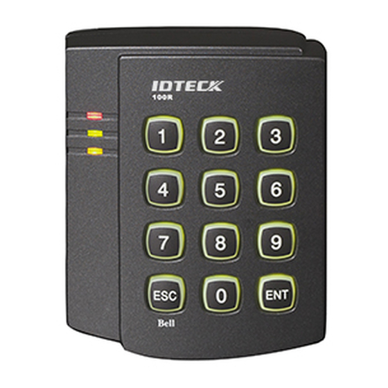
Dark Pearl Gray / Polycarbonate Dimension (W x H x T) 87mm x 100mm x 31mm (3.4” x 3.94” x 1.22”) Weight 210g (0.46lbs) Certification UL, FCC, CE, MIC 5. Front Panel Description Main Unit of Star 100R / iPASS 100R... -
Page 6: Identifying Supplied Parts
6. Identifying Supplied Parts Please unpack and check the contents of the box. Main Unit Wall Mount O-Ring User’s Manual (1ea) (1ea) (5ea) (1copy) 3.5*40 Screw 3.5*12 Screw Anchor Bolt (4ea) (4ea) (4ea) 7. Installation 7-1. Tear off page 38 and use the provided template to drill two 6-32 holes and one 1/2" hole on the proper location of the wall to mount the Wall Mount bracket as shown below. -
Page 7: Wiring Color Table
7-2. Using 2 screws, install wall mount to the wall. ※CAUTIONS Before mounting the STAR 100R unit to the Wall Mount bracket, operational testing of the unit should be completed, as the locking pins will lock the unit to the Wall Mount. Removing the unit from the Wall Mount bracket after they have been installed together may cause damages to the bracket and render its effectiveness. - Page 8 OPTIONAL: Wiegand Output Function Applicable to: v5.2.0 of the 100R v2.2.0 of the IP100R You can configure the 100R to generate output in Wiegand format and use it like a reader. (The 100R can output data from card reading, but doesn’t output data from keypad input.) JP9, JP10 : Short PIN1 and PIN2 -->...
-
Page 9: System Wiring For Typical Application
9. System Wiring for Typical Application . Power Connection - Connect (+) wire of DC +12V power to Red wire and Red/White banded wire. - Connect Power GND (-) wire of DC +12V to Black wire and Black/White banded wire. . - Page 10 . Exit Button Connection - Connect one of the wires of Exit Button to Exit Button Input, Yellow/Red banded wire. - Connect the other wire of Exit Button to Power GND (-) wire. (If a normally closed Exit button is used, then see section 12-67 to change the detection scheme from the defaulted setting) .
-
Page 11: Initial Setup
- Connect (-) wire of Chime Bell unit to Power GND (-) wire. 10. Initial Setup The Flash memory of each shipped STAR 100R contains a minimum set of defaulted values, but it does not have any other preprogrammed values or user’s data in it, therefore, Initial Setup is required upon the first time the unit is powered-up in order to operate the unit properly. - Page 12 Personal Identification Number (PIN) for each User Access Card..Configuration Card User Access Cards + PINs Configuration Card again to end task (4) The first card read becomes the Configuration Card and the following RF Cards + PINs are registered as User Access Cards with assigned PINs.
- Page 13 ..10-5. Factory Defaulted Setting Values After the Initial Setup, the Main Unit uses the factory defaulted setting values below to execute the normal operation mode. You may want to change these factory setting values or modify your User Access list;...
-
Page 14: Operation
11. Operation 11-1. Normal Operation Mode (Safe Mode) When the Main Unit operates in normal mode, the yellow LED is flashing every second. 11-2. Open the Door When a registered Card (or PIN) is read, the Door will open for 3 seconds along with the"do-mi-sol-do"... -
Page 15: Setting Changes
11-7. Chime Bell Operation key can be used to activate an external Chime Bell for 5 seconds, the defaulted value. 12. Setting Changes Configuration Card/PIN is required to change existing or defaulted setting values or to manage user’s access. First, present the Configuration Card (or enter the Configuration PIN) and enter the 2-digit command code. - Page 16 Test Alarm time set by command "26" Test Alarm time set by command "27" Change Chime Bell activating time Open door unconditionally Close door unconditionally Enable QUICK ACCESS MODE Disable QUICK ACCESS MODE Enable Toggle Mode for Lock control Disable Toggle Mode for Lock control Enable Unlock followed by Door Contact Disable Unlock followed by Door Contact Disable Melody sound (turning off both the melody &...
- Page 17 12-11. Add User Access Cards (RF CARD ONLY MODE) ….. ….. Configuration Card Command Cards to be registered Configuration Card 12-12. Add User Access Cards (RF CARD + PIN MODE) ….. Configuration Card Command Cards to be registered ..Configuration Card 12-13.
- Page 18 <TABLE 1> SETTINGS FOR COMMAND Symbol Setting Values Examples/Remarks (You must add value ① and ②) EX1)Activate Door Relay Setting value for activating time In Safe & Secure Mode ① Activate Mode Value ① Safe & Secure Mode Activate only in Secure Mode : 00 ②...
- Page 19 12-23. Change Alarm Time When Try-Out Error Detected (Refer to Table 1 for OM, =00~99 sec., Defaulted Alarm time = 10 sec.) Configuration Card Command Output Mode Door time Alarm Time TTL time /Configuration PIN 12-24. Change Alarm Time When Door Contact Error Detected (Refer to Table 1 for OM, =00~99 sec.) Door Open Time-out setting is required for activating, refer to 12.81.
- Page 20 12-30. Change Alarm Time When Duress Alarm Detected =00~99 sec., Defaulted TTL time= 03 sec.) Configuration Card Command TTL time /Configuration PIN 12-31. Test Door Open Time Set By Command "21" 12-32. Test Alarm Time Set By Command "22" 12-33. Test Alarm Time Set By Command "23" 12-34.
- Page 21 12-44. Disable QUICK ACCESS MODE Configuration Card (Defaulted setting=Disable) /Configuration PIN 12-45. Enable Toggle Mode for Lock Control If you set Enable Toggle Mode, Door will be toggled open and close function when the registered card or PIN entered. You may use this function for Arm/Disarm for buglar alarm system.
- Page 22 12-60. Change Keypad Lock-out Time When Try-Out Error Detected =00~99 min., Defaulted Keypad Lock-out time= 01 min.) Configuration Card Command Keypad Lock-out time /Configuration PIN 12-61. Set AUX Input #1 Detection from ‘L’ to ‘H’ AUX#1 input is detected on the raising edge of AUX#1 input Configuration Card /Configuration PIN 12-62.
- Page 23 12-69. Set Door Contact Sensor Input Detection from ‘L’ to ‘H’ Door Contact input is detected on the raising edge of Door Contact input Configuration Card /Configuration PIN 12-70. Set Door Contact Sensor Input Detection from ‘H’ to ‘L’ (Defaulted setting) Door Contact input is detected on the falling edge of Door Contact input Configuration Card /Configuration PIN...
- Page 24 12-81. Set Door Open Time-out for Door Contact Sensor (tt=00~99 sec., Defaulted value = 00 sec. means no detect Door Contact Sensor, refer to 12.24 for Alarm time settings) Configuration Card Command Door Open time-out /Configuration PIN 12-82. Set Number of Times of Try-Out (NN=00~99 times, Defaulted Try-out numbers= 05 times) Configuration Card Command...
-
Page 25: Initialization
Initialization When you lost the Configuration Card or forgot the Master PIN number, you may need to re-initialize the unit for new setup. There is a hard-wired Initialize function on the unit. ※ WARNING: You may lose all setup data after execute Initialize. 13-1. -
Page 26: Fcc Registration Information
14. FCC Registration Information FCC REQUIREMENTS PART 15 Caution: Any changes or modifications in construction of this device which are not expressly approved by the manufacturer for compliance could void the user's authority to operate the equipment. NOTE: This device complies with Part 15 of the FCC Rules. Operation is subject to the following two conditions;... -
Page 27: Troubleshooting
15. Troubleshooting If a problem occurs during the use of this product, do not attempt to disassemble the product by yourself. Please check the following suggestions. If your problem still persists, contact our customer service center. [Operation] ● Problem When power is first supplied, 3 LEDs of 100R blinks only and an RF card doesn’t recognize. ●... - Page 28 ● Problem The 100R operates suddenly on general mode during setting or registering a user on mode selection. ● Cause ▶ Over standby time on mode selection ● Solution ▶ If not entering a key or a card within 20 sec. on mode selection, the product operates on general mode automatically.
- Page 29 ● Problem User card or PIN cannot be deleted. ● Cause ▶ An error in using a product or in system settings ▶ System malfunction/data damaged or lost due to an external noise or a short circuit. ● Solution ▶ Make sure that installation and operation are normal. ☞...
- Page 30 ● Problem Registering/deleting a card and setting change cannot be used because of loosing a master card or PIN. ● Cause ▶ A user carelessness ● Solution ▶ When loosing a master card or PIN, if you change product’s settings, you should initialize the product.
- Page 31 Make sure to consult a technician before separating or initializing Caution a product. ● If the problem still persists, contact our customer service center. [Communication] ● Problem Although the 100R connects with PC, communication was not at all. ● Cause ▶...
- Page 32 ● Solution ▶ Check if any buzzer goes off when the keypad is pressed. ☞ If the buzzer goes off: 1. Enter the master card (or PIN: 4 to 6digit (mode 03 or 05) + ENT). 2. Enter “73 + ENT” to “Enable Keypad Input To Enter ID Number”. See “Setting Changes ”...
- Page 33 Caution Make sure to use a NO (Normal Open)-type exit button. ☞ Check the exit button operation. 1. Check the condition of the connection cable (a short circuit or cut) between and the 100R. 2. Connect two wires from the exit button. - If the FACE007 operates when the exit button is pressed.
- Page 34 ● Solution ▶ Make sure of connection between the exit button and the 100R and of operation of exit reader. ☞ Check the connection between the exit button and the 100R. ☞ Check the exit reader operation. 1. Check the condition of the connection cable (a short circuit or cut) between the exit reader and the 100R.
- Page 35 Caution See “Installation ” to connect the exit reader. ● If the problem still persists, contact our customer service center. ● Problem A door lock will not work. ● Cause ▶ An error in connection between the door lock and the 100R ▶...
- Page 36 The connection between a door lock and the 100R may vary depending Caution on the door lock type and its operation type (Normal Open, Normal Close). ● If this does not solve the problem, proceed with the following steps. ☞ Check the door lock operation and the connection between the door lock and the 100R. 1.
-
Page 37: Warranty Policy And Limitation Of Liability
4) to any losses, defects, or damages caused by lightning or other electrical discharge, natural disaster, misuse, accident or neglect. This Limited Warranty is in lieu of all other warranties, obligations, or liabilities on the part of IDTECK, and IDTECK DISCLAIMS ANY AND ALL WARRANTY, WHETHER EXPRESS OR IMPLIED, OF MERCHANTABILITY OR FITNESS FOR A PARTICULAR PURPOSE.IDTECK does not, and cannot,... - Page 38 RMA REQUEST FORM IDTECK accepts only on-line RMA requests on our Website (www.idteck.com). Please provide us with basic information in the below form so that we can understand your problems better. Send us back this form with your products after an RMA code is issued on our Website. This form is not compulsory.
-
Page 39: Template
17. Template... - Page 40 The specifications contained in this manual are subject to change without notice at any time. 5F, Ace Techno Tower B/D, 684-1, Deungchon-Dong, Gangseo-Gu, Seoul, 157-030, Korea Tel : +82-2-2659-0055 Fax : +82-2-2659-0086 E-mail : webmaster@idteck.com MAM100RHE5X Dec. 2008 Copyright © IDTECK Co., Ltd.
Need help?
Do you have a question about the Star 100R and is the answer not in the manual?
Questions and answers