Table of Contents
Advertisement
Quick Links
AlphaStation™ 500 Series
User Information
Part Number: EK-ALPH5-UI. B01
January 1997
This book introduces the AlphaStation 500 Series system. Use the information in this
book to configure, start, use, update, and troubleshoot your system. You will also find
general system information, such as console commands and system care, in this book.
Revision/Update Information:
This is revision.
Digital Equipment Corporation
Maynard, Massachusetts
Advertisement
Table of Contents
Troubleshooting

Related Manuals for Digital Equipment AlphaStation 500 Series


Summary of Contents for Digital Equipment AlphaStation 500 Series
-
Page 1: User Information
Part Number: EK-ALPH5-UI. B01 January 1997 This book introduces the AlphaStation 500 Series system. Use the information in this book to configure, start, use, update, and troubleshoot your system. You will also find general system information, such as console commands and system care, in this book. - Page 2 First Printing, December 1995 Revised, January 1997 Digital Equipment Corporation makes no representations that the use of its products in the manner described in this publication will not infringe on existing or future patent rights, nor do the descriptions contained in this publication imply the granting of licenses to make, use, or sell equipment or software in accordance with the description.
- Page 3 FCC CLASSIFICATION There are many variants of AlphaStation 500 Series systems. Your AlphaStation 500 Series system may be classified as either a Class A or a Class B FCC/EMC device, depending upon its options and configuration.. To determine your system’s classification, look at the FCC Classification Label on the bottom of the system.
- Page 4 FCC NOTICE -- CLASS B DEVICE (continued) This equipment generates, uses, and can radiate radio frequency energy and, if not installed and used in accordance with the instructions, may cause harmful interference to radio communications. However, there is no guarantee that interference will not occur in a particular installation.
-
Page 5: Table Of Contents
Digital UNIX ......................2-8 OpenVMS........................2-8 Switching Console Firmware ..................2-9 If No Operating System Is Installed ................2-9 Turning Off Your System ......................2-9 Computer Security.......................2-10 Security Lock ....................... 2-10 Passwords ........................2-10 Posture and Work Habits ....................2-10 AlphaStation 500 Series User Information v... - Page 6 PCI Bus ........................3-31 Installing Expansion Modules..................3-32 Replacing the Left Side Panel and Top Cover ..............3-34 Connecting External Options....................3-36 Connecting a Printer or Other Parallel Device .............. 3-36 Connecting an External SCSI Option................3-36 vi AlphaStation 500 Series User Information...
- Page 7 SRM Console ........................A-8 SRM Console Conventions .................... A-9 SRM Console Shortcut Keys..................A-10 Boot Command......................A-11 Boot Command Examples..................A-12 Set Command ......................A-13 Set Command Examples ..................A-14 Show Command ......................A-14 AlphaStation 500 Series User Information vii...
- Page 8 SROM Selection Jumpers .................... C-12 Ethernet Interface ......................C-13 Software Switches ....................C-13 Selecting the ThickWire/ThinWire or Twisted Pair Ports........C-13 D Device Mapping Introduction.......................... D-1 I/O Address Map ........................D-1 Interrupt Map ........................D-2 viii AlphaStation 500 Series User Information...
- Page 9 External Connection Jacks ..................... G-4 Software ........................G-4 Microsoft Windows NT Workstation Operating System..........G-4 Digital UNIX Operating System ..................G-4 OpenVMS Operating System ..................G-5 H Equipment Log Introduction......................... H–1 Equipment Log........................H–1 AlphaStation 500 Series User Information ix...
- Page 10 Figure 1-1 Front Controls, Indicators, and Drive Bay Locations ......1-3 Figure 1-2 Rear Connectors (Rear View)............. 1-4 Figure 1-3 Typical Keyboard Layout..............1-6 Figure 2-1 AlphaStation 500 Series System ............2-2 Figure 2-2 System Enclosure Airflow..............2-4 Figure 2-3 Voltage Select Switch ................. 2-5 Figure 2-4 Connecting Cables and the Power Cord..........
- Page 11 Table C-11 Input Power Requirements ..............C-9 Table C-12 System Board Jumpers ..............C-12 Table C-13 SROM Selection Jumpers..............C-12 Table D-1 I/O Address Map................. D-1 Table D-2 Main Interrupt Logic IRQ Pin Assignments ........D-3 AlphaStation 500 Series User Information xi...
- Page 12 Table G-5 SW1 and SW2 Jumpers Audio Module Base Address ......G-3 Table H-1 Hardware Components................H–2 Table H-2 SCSI Addresses ..................H–2 Table H-3 Hardware Configuration ..............H–3 Table H-4 Installed Software................H–3 Table H-5 Additional Component Information ............H–3 xii AlphaStation 500 Series User Information...
- Page 13 This book introduces the Digital AlphaStation 500 Series system. Use the information in this book to configure, start, use, update, and troubleshoot your Digital AlphaStation 500 Series system. You can also find general system information such as console commands and system care in this book.
- Page 14 Appendix F, Starting an Operating System Installation, provides the information you need to begin an operating system installation. • Appendix G, Sound Card Overview, describes the Digital AlphaStation 500 Series system sound card. • Appendix H, Equipment Log, contains tables that you can use to record information about your system hardware and software components.
- Page 15 EISA configuration utility EISA extended industry-standard architecture Floppy Drive Interconnect flashROM electrically erasable, rewriteable, nonvolatile memory feet gigabyte hertz International Electrotechnical Commission input/output interrupt request industry-standard architecture ISACFG ISA configuration file International Organization for Standardization AlphaStation 500 Series User Information xv...
- Page 16 SIMMs single in-line memory modules system reference manual (the Digital UNIX and OpenVMS consoles) SROM serial read-only memory Underwriters Laboratories value-added reseller V AC volts alternating current Open VMS Operating System watt xvi AlphaStation 500 Series User Information...
-
Page 17: Special Notices
AlphaStation 500 Series system. • AlphaStation 500 Series Installation Information (order number EK-ALPH5-IN), which presents a graphical overview of the AlphaStation 500 Series system installation. Contact your distributor or Digital representative for other available product-related information or visit the Digital WorkStation web site. - Page 18 Digital in the following ways: • Internet electronic mail to: readers_comments@zk3.dec.com • Mail: Digital Equipment Corporation Shared Engineering Services 129 Parker Street - PKO3-2/21J Maynard, MA 01754-2199 Please reference order number EK-ALPH5-UI. B01 in your correspondence. xviii AlphaStation 500 Series User Information...
-
Page 19: System Overview
PCI cards, video upgrades, and hard disk drives. The AlphaStation 500 Series is a high-performance system that uses the latest microprocessor technology. The system can stand alone or function as a client in an office network environment. -
Page 20: System Unit
System Overview System Unit Your AlphaStation 500 Series system uses a high-performance Alpha architecture CPU. The system unit includes: • Two accessible I/O bays: one for 3.5 inch x 1 inch floppy disk or 3.5 inch tape devices and one for 5.25 inch x 1.6 inch CD-ROM •... -
Page 21: Enclosure Front Panel
LED Indicator DC On, lights when the system is on. LED Indicator Lights to indicate SCSI activity. Louvered air intake Passageway for cooling air to enter the system. (Do not block the air intake.) AlphaStation 500 Series User Information 1-3... -
Page 22: Enclosure Rear Panel
System Overview Enclosure Rear Panel Figure 1-2 shows the rear controls and connectors. Table 1-2 lists the rear controls and connectors and describes their functions. MA00995 Figure 1-2 Rear Connectors (Rear View) 1-4 AlphaStation 500 Series User Information... -
Page 23: Table 1-2 Rear Connectors
Connects a VMS or PS/2 style keyboard Mouse connector Connects a PS/2-compatible mouse COM1 - Serial port Connects serial devices connector COM2 - Serial port Connects serial devices connector AC power connector Connects the system to AC power AlphaStation 500 Series User Information 1-5... -
Page 24: The Keyboard
_________________________ NOTE____________________________ You can adjust the angle of the keyboard for your comfort. The underside of the keyboard has feet that swing down and lock into place. ___________________________________________________________ Figure 1-3 Typical Keyboard Layout 1-6 AlphaStation 500 Series User Information... -
Page 25: Table 1-3 Key Groups And Functions
These keys control the movement of the highlighted cursor on the monitor screen. Alpha-numeric key group These typewriter-specific keys feature automatic-repeat capability. If you press and hold down any of these keys, the keystroke repeats automatically until released. AlphaStation 500 Series User Information 1-7... -
Page 27: Getting Started
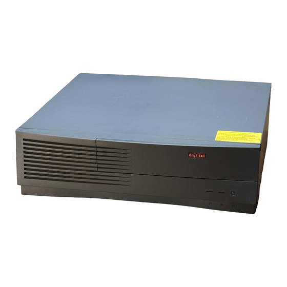
This chapter describes how to install, start, restart, and turn off your AlphaStation 500 Series system. You can also find information here about preloaded software as well as guidelines for system security. Figure 2-1 shows a typical AlphaStation 500 Series system. ________________________WARNING __________________________... -
Page 28: Before Starting Your System
Getting Started MA01000 Figure 2-1 AlphaStation 500 Series System Before Starting Your System Before you start your system, follow this procedure: 1. Read and understand the information supplied with your system. 2. Select a well-ventilated site near a grounded power outlet and away from sources of excessive heat. -
Page 29: Identifying The Correct Ac Power Cord
The cords are UL-listed and CSA-certified, rated for use at 250V AC with a current rating that is at least 125% of the current rating of the Digital AlphaStation 500 Series system. In Europe, the cordage carries the <HAR> mark. -
Page 30: Installing Your System
Getting Started Installing Your System The AlphaStation 500 Series Installation Information you received with your system graphically outlines the steps to follow to install your system. 1. Make sure you received all of your system components. Use Appendix H, Equipment Log, to list your equipment. -
Page 31: Connecting System Components
Getting Started Connecting System Components To connect the components of your AlphaStation 500 Series system, refer to Figure 2-4 and follow this procedure: __________________________NOTE ____________________________ The AlphaStation 500 Series system runs on 88V–264V AC and 47–63 Hz. ____________________________________________________________ 1. Confirm that the voltage selector switch matches your local voltage (either 115 Volts or 230 Volts), as Figure 2-3 shows. -
Page 32: Figure 2-4 Connecting Cables And The Power Cord
Audio connector (Headphone - top, Microphone - second from bottom) š Keyboard/mouse connectors (Keyboard - top, Mouse - bottom) › Monitor connector œ Network connectors (Twisted pair - top, ThinWire - bottom) Power connector 2-6 AlphaStation 500 Series User Information... -
Page 33: Network Connection
SCSI cable to the SCSI port on the rear of the system. See the section on SCSI Termination in Chapter 3 for additional information. Network Connection The AlphaStation 500 Series MAU module has ThinWire, and twisted-pair connectors for connecting to a network. Use the appropriate connector for your application. Starting Your System Perform the following steps to start your AlphaStation 500 Series system: 1. -
Page 34: Preloaded Operating System Software
Getting Started Preloaded Operating System Software Your AlphaStation 500 Series system comes with one of the following operating systems preloaded: • Digital UNIX • OpenVMS _________________________ NOTE____________________________ Windows NT is available but is not preloaded on your AlphaStation 500 Series system. -
Page 35: Switching Console Firmware
1. Close any application data files you have open as well as any applications you have running. Most application programs prompt you to save the information before closing. 2. Shut down the operating system with the appropriate command from Table 2-1 on the following page. AlphaStation 500 Series User Information 2-9... -
Page 36: Computer Security
4. Do not turn off power to your system and peripherals until the shutdown sequence completes. Computer Security Use the security lock and passwords to protect your Digital AlphaStation 500 Series system. Security Lock To avoid theft of internal components, your Digital AlphaStation 500 Series system comes with a security key lock, which is located on the back of your system unit. -
Page 37: Figure 2-6 Recommendations And Posture And Work Habits
Your upper body is erect and your lower back is supported with a backrest. AlphaStation 500 Series User Information 2-11... - Page 38 If you experience pain or discomfort while using your system, rest and review the instructions for posture and work habits. If the pain or discomfort continues after resuming work, discontinue use and report the condition to your job supervisor or physician. ___________________________________________________________ 2-12 AlphaStation 500 Series User Information...
-
Page 39: Installing System Options
Cable layout for power, SCSI, FDI and audio cables ________________________ CAUTION ___________________________ When working on the internals of the system unit (for example, replacing an option), you must wear a grounded wrist strap. ____________________________________________________________ AlphaStation 500 Series User Information 3-1... -
Page 40: Top Cover/Left Side Panel
Installing System Options Top Cover/Left Side Panel To gain access to the inside of the AlphaStation 500 Series system unit, remove the top cover, and the left side panel. Removing the Top Cover and Left Side Panel To remove the top cover and left side panel, follow this procedure: 1. -
Page 41: Figure 3-2 Removing The Top Cover And Left Side Panel
6. If necessary to access the item you are servicing, the left side panel, nearest to PCI options, is removed by sliding the panel toward the rear of the system unit (as shown in Figure 3-2) and removing it. MA00988 Figure 3-2 Removing the Top Cover and Left Side Panel AlphaStation 500 Series User Information 3-3... -
Page 42: System Unit Components
Installing System Options System Unit Components Figure 3-3 shows the location of the AlphaStation 500 Series system unit components. Table 3-1 lists the system unit components. MA00989 Figure 3-3 System Unit Components 3-4 AlphaStation 500 Series User Information... -
Page 43: Table 3-1 System Unit Components
Left lower internal drive bay for 3.5-inch x 1 inch device, not available with tape option System cooling fan System board PCI expansion slots, (three 32-bit slots) PCI expansion slot, (one 64-bit slot) AlphaStation 500 Series User Information 3-5... -
Page 44: System Board
Installing System Options System Board Figure 3-4 shows the location of the AlphaStation 500 Series system board components. Table 3-2 describes these components. MA00997 Figure 3-4 System Board Components 3-6 AlphaStation 500 Series User Information... -
Page 45: Table 3-2 System Board Components
Connectors for DIMM memory modules (J23, J24, J25, J26, J27, J28, J29, J30) Cache System fan connector (J1) Alpha CPU Mounting holes (9 places) CIA Bridge Riser card (J34) Media Adapter Unit (MAU) Connector Header (J32) Internal SCSI Header (J37) AlphaStation 500 Series User Information 3-7... -
Page 46: System Memory
DIMMs. Adding more memory allows your system to run larger, more memory- intensive software. You can increase your system's RAM to 1 GB. Cache Memory Each AlphaStation 500 Series system has either 2 MB or 8 MB on the system board. Cache size depends on the Model ordered. Memory Configuration Rules •... -
Page 47: Adding Or Removing Memory Modules (Dimms)
DIMM to insure proper fit into DIMM connector slot. Install the DIMM into the socket by inserting connecting end of the DIMM, straight down into the socket until the two latches engage and lock. Refer to Figure 3-6. Repeat this process for all four DIMMs. AlphaStation 500 Series User Information 3-9... -
Page 48: Figure 3-6 Installing A Dimm
Figure 3-6 Installing a DIMM 4. Replace top cover, secure with screw and lock the key/lock, as described earlier in this chapter. 5. Connect the power cord and plug it into the wall outlet. 3-10 AlphaStation 500 Series User Information... -
Page 49: Storage Devices
Installing System Options Storage Devices The AlphaStation 500 Series system supports five storage devices. The AlphaStation 500 Series system comes equipped with two accessible devices, a slimline 3.5-inch diskette or optional tape drive, and a 5.25-inch half-high removable media device (CD-ROM). In addition, up to three non-accessible, optional hard drives may be installed within the internal storage bays. -
Page 50: Scsi Termination
An external terminator is required when the SCSI port is not being used. Internal SCSI Termination The internal SCSI cable used for the AlphaStation 500 Series is a flat ribbon cable with integrated termination. Therefore, NO storage devices should have termination enabled. -
Page 51: Installing Optional Internal Storage Devices
The CD-ROM and optional tape drives are narrow SCSI devices. You must use a wide-to-narrow SCSI adapters with it. One adapter (part number 17- 04009-01) is supplied with the system. • If you are using Wide SCSI drives, you do not need the adapter. ____________________________________________________________ AlphaStation 500 Series User Information 3-13... -
Page 52: Removing The Cd-Rom
It is not necessary to remove the cables from the CD-ROM. Remove cables from the drive only after the assembly has been lifted out of the system unit, if you must remove them. MA00982 Figure 3-7 Removing the CD-ROM Bracket 3-14 AlphaStation 500 Series User Information... -
Page 53: Removing The Drive Tray From The Lower Right Side Inner Bay
š of enclosure that releases that drive tray. Slide it back , lift it up and out of the enclosure, as shown in Figure 3-8. MA00980 Figure 3-8 Removing the Hard Drive Tray Bracket AlphaStation 500 Series User Information 3-15... -
Page 54: Installing Drives In The Right Side Bracket
1.6 inch high storage device in the lower position only, or up to two 1.0 inch high devices (one in upper position and one in lower position). ___________________________________________________________ MA00967 Figure 3-9 Installing Drives in the Right Side Bracket 3-16 AlphaStation 500 Series User Information... -
Page 55: Figure 3-10 Cabling The Optional Hard Drives
“1” or “2” printed on the circuit board near one end of the connector. 4. Replace the CD-ROM bracket assembly. Slide it forward until it locks in place. 5. Connect the power cord and plug it into the wall outlet. AlphaStation 500 Series User Information 3-17... -
Page 56: Figure 3-11 Fdi/Scsi Cable Routing
*RULE: Use only one 3.5 inch x 1.0 inch device, or two 3.5 inch x 1.0 inch devices or one 3.5 x 1.6 inch device. Do not mix a 3.5 inch x 1.0 inch and a 3.5 inch x 1.6 inch device in this storage tray. 3-18 AlphaStation 500 Series User Information... - Page 57 , there is a drive end and a controller end. You must check the label on the cable to insure correct orientation. Make sure drive end is connected to drive, controller end connected to system board connector (J38). ____________________________________________________________ AlphaStation 500 Series User Information 3-19...
-
Page 58: Figure 3-12 Audio Cable Routing
Audio Card Left and Right LINE IN from CD-ROM š CD-ROM Left and Right LINE OUT › CD-ROM Audio Cable œ Cable to Internal speaker Cable connects to internal speaker, located in front panel. 3-20 AlphaStation 500 Series User Information... -
Page 59: Figure 3-13 Power Cable Configuration
*RULE: Use only one 3.5 inch x 1 inch device, or two 3.5 inch x 1 inch devices or one 3.5 x 1.6 inch device. Do not mix a 3.5 inch x 1 inch and a 3.5 inch x 1.6-inch device in this storage tray. AlphaStation 500 Series User Information 3-21... -
Page 60: Figure 3-14 Mau Cable Configurations
Installing System Options MA00970 Figure 3-14 MAU Cable Configurations ™ MAU card (cable connects to MAU card connector J2) š MAU cable (connects to system board connector J32) 3-22 AlphaStation 500 Series User Information... -
Page 61: Figure 3-15 Fan And Led Cable Connections
Installing System Options MA00971 Figure 3-15 Fan and LED Cable Connections ™ Cable connection for LEDs and Halt/Reset lights (J5) š Cable connection for Cache Fan (J3) › Cable connection for System Fan (J1) AlphaStation 500 Series User Information 3-23... -
Page 62: Installing A Hard Disk Drive In The Left Side Storage Bay
4. Remove the data and power cables from the devices in the floppy drive assembly. Note the position of the cables so that you can reconnect them to the correct devices later. 3-24 AlphaStation 500 Series User Information... -
Page 63: Figure 3-16 Removing The Floppy Drive Tray Assembly
Installing System Options MLO-013734 Figure 3-16 Removing the Floppy Drive Tray Assembly AlphaStation 500 Series User Information 3-25... -
Page 64: Removing The Floppy Drive From The Original Drive Tray
œ 2. Remove the EMI shield that is under the floppy drive. MA00977 Figure 3-17 Removing the Floppy Drive (Original Tray) 3-26 AlphaStation 500 Series User Information... -
Page 65: Removing The Floppy Drive From The Drive Tray (Re-Designed)
› œ 2. Remove screws , and the EMI shields & , that are under the floppy drive. MLO-013731 Figure 3-18 Removing the Floppy Drive (Re-designed Tray) AlphaStation 500 Series User Information 3-27... -
Page 66: Installing An Optional Hard Drive In The Original Left-Side Drive Tray
2. Replace the EMI shield and reinstall the floppy drive to the drive tray with the four screws (Figure 3-17). 3. Connect SCSI and power cables. (See Figures 3-10, 3-11, and 3-13) 4. Reinstall the drive tray assembly back into position in the left-side storage bay. 3-28 AlphaStation 500 Series User Information... -
Page 67: Installing An Optional Hard Drive In The Re-Designed Left-Side Drive Tray
1. Insert the optional hard drive into the lower position on the drive tray. Secure with the four mounting screws to the drive tray as shown in Figure 3-20. MLO-013732 Figure 3-20 Installing Optional Hard Drive (Re-designed Tray) AlphaStation 500 Series User Information 3-29... -
Page 68: Installing An Optional Tape Drive In The Redesigned Left-Side Drive Tray
3. Push bracket forward until tabs lock tray in place. 4. Replace and lock the top cover, as described at the end of this chapter. 5. Connect the power cord and plug it into the wall outlet. 3-30 AlphaStation 500 Series User Information... -
Page 69: Pci Expansion Options
Installing System Options PCI Expansion Options The AlphaStation 500 Series system features four expansion slots, one 64-bit PCI slot, and three 32-bit PCI slots. Refer to Figure 3-22 and Table 3-4. 64 Bit PCI Option Slot 32 Bit PCI Option Slot... -
Page 70: Installing Expansion Modules
__________________________ Note ____________________________ To ease future installations, it is recommended that PCI options be installed in the bottom PCI slot first. ___________________________________________________________ š 6. Replace the screw to secure the module at the rear panel. 3-32 AlphaStation 500 Series User Information... -
Page 71: Figure 3-23 Installing An Expansion Module
Installing System Options MA00984 Figure 3-23 Installing an Expansion Module AlphaStation 500 Series User Information 3-33... -
Page 72: Replacing The Left Side Panel And Top Cover
(See Figure 3-24) 3. Connect the power cord and plug it into the wall outlet and turn on the system. For more information on operating system-specific options, refer to your operating system and option documentation. 3-34 AlphaStation 500 Series User Information... -
Page 73: Figure 3-24 Replacing The Top Cover
Installing System Options MA00987 Figure 3-24 Replacing the Top Cover AlphaStation 500 Series User Information 3-35... -
Page 74: Connecting External Options
68-pin type connector. Terminate the new end of the bus at the last external SCSI device, using the appropriate terminator. Make sure that any other external SCSI devices have their terminators removed or disabled. 3-36 AlphaStation 500 Series User Information... -
Page 75: Troubleshooting
Refer to the documentation supplied with additional options if you are experiencing problems with specific options that you have installed. Initial Troubleshooting To troubleshoot your AlphaStation 500 Series system initially, follow this procedure: 1. Check that the power indicator is on. 2. Check the power indicator on the monitor. -
Page 76: General Troubleshooting
“Serial.” See pp. A-1 and A-2. Refer to the video module documentation for more information. Try another monitor. Monitor is defective. Replace the video module. Defective video controller module. 4-2 AlphaStation 500 Series User Information... -
Page 77: Table 4-1 System Troubleshooting (Continued)
Digital UNIX and OpenVMS: Use the SRM console show envar and set enva r commands to check and set the values assigned to boot-related variables such as auto_action, bootdef_dev, and boot_osflag. (Refer to Appendix A, “Console Commands.”) AlphaStation 500 Series User Information 4-3... -
Page 78: Table 4-1 System Troubleshooting (Continued)
IDs. Display hardware configuration (ARC) Refer to the hard disk drive documentation. SCSI bus termination Check that the SCSI bus is incorrectly set. properly terminated. Refer to Chapter 3 for more information. 4-4 AlphaStation 500 Series User Information... - Page 79 Mouse ball sticking. Clean the mouse. Refer to Appendix B, System Care, for information on cleaning the mouse. Turn the system off before connecting the keyboard. Turn the system off before connecting the mouse. AlphaStation 500 Series User Information 4-5...
- Page 80 Use a diskette of the proper density for your drive. Diskette is worn or Try another diskette. damaged. Diskette is write-protected. Slide the write-protect switch so the hole is not visible. Diskette drive is empty. Insert a diskette. 4-6 AlphaStation 500 Series User Information...
-
Page 81: Table 4-3 Monitor Troubleshooting
Wrong type of monitor. Try another monitor. Defective monitor. Try another monitor. Monitor signal cable Straighten any bent connector incorrectly installed. pins and then reconnect the monitor. AlphaStation 500 Series User Information 4-7... -
Page 82: Srom Status And Error Codes
Initializing memory test Testing bcache bits Testing memory bits Testing bcache addresses Testing memory addresses Testing bcache cells Testing memory cells Initializing all memory Loading flash ROM code Reinitializing cpu/system interface Code execution complete 4-8 AlphaStation 500 Series User Information... -
Page 83: Table 4-4 Status And Error Codes (Continued)
System finds a bad CIA memory csr Bcache data path error Bcache address line error Bcache cell error Reserved ROM data path read error Reserved * AlphaStation 500 Series have no MMB’s, this is a message for AlphaStation 600 Series. AlphaStation 500 Series User Information 4-9... -
Page 84: Equipment Log
For your convenience, Appendix H includes a form on which you may record all model numbers and serial numbers for your hardware components (system unit, monitor, keyboard, and mouse) and system hardware configuration information (CPU, memory size, drive size, ports, and so on). 4-10 AlphaStation 500 Series User Information... -
Page 85: A Console Commands
The ARC console supports the use of the Windows NT operating system. The ARC console uses a menu interface. When an AlphaStation 500 Series system with Windows NT is turned on, a menu similar to the following displays after initialization: ARC Multiboot Alpha AXP Version 4.xx... -
Page 86: Commands You Need To Know
2. Select Set default environment variables and press [Enter]. 3. For the system partition location, select SCSI Hard Disk and press [Enter]. 4. Enter the SCSI bus number (typically, 0) and the SCSI ID of the disk where the partition resides. A-2 AlphaStation 500 Series User Information... -
Page 87: Set Default Configuration
For example, when selected, the Set default configuration command prompts you to make the following choices: Select monitor resolution: 1280x1024 1024x768 800x600 640x480 Select first floppy drive capacity: 5.25” 1.2MB 3.5” 1.44MB 3.5” 2.88 none AlphaStation 500 Series User Information A-3... -
Page 88: Setting The Date And Time
If you selected English, your Alpha system displays the Boot menu (or the Setup menu if you selected the Set system language command from there), and you have completed this task. A-4 AlphaStation 500 Series User Information... -
Page 89: Manage Boot Selection Menu
SCSI Bus 0 Hard Disk 0 Partition 2 New System Partition (The partition defined by the Set default environment variables command must be one of the available choices.) • The osloader directory and name. AlphaStation 500 Series User Information A-5... -
Page 90: Machine Specific Setup
You reach the Machine specific setup menu from the Setup menu. Use this menu to control PCI parity checking, which is (by default) set to On, and SCSI termination of the external portion of the SCSI bus, which is (by default) set to Internal. A-6 AlphaStation 500 Series User Information... -
Page 91: Setting Pci Parity
The sections that follow describe ARC console commands that you may find useful. Setup Autoboot The Setup autoboot command is located in the Setup menu. Use this command to enable automatic booting of the system. When you enable autoboot, you will also be AlphaStation 500 Series User Information A-7... -
Page 92: Install New Firmware
For a complete list of SRM commands, type help at the SRM prompt (>>>). This section describes environment variables and the following commands: • • boot • • • • show • • examine • • deposit A-8 AlphaStation 500 Series User Information... -
Page 93: Srm Console Conventions
Treated as a single space. Command abbreviations Allowed, if not ambiguous. Command qualifiers or options Prefix with a space and a dash (-). Numbers Hexadecimal, unless otherwise specified. (Note: Registers such as R0–R31 are shown in decimal notation.) AlphaStation 500 Series User Information A-9... -
Page 94: Srm Console Shortcut Keys
Suppresses/resumes (toggles) console output. [Ctrl]+[Q] XON, resumes the flow of data to the console. [Ctrl]+[S] XOFF, stops the flow of data to the console. [Ctrl]+[U] Deletes the entire line. [Ctrl]+[R] Retypes the current command line. A-10 AlphaStation 500 Series User Information... -
Page 95: Boot Command
Specifies a device path or list of devices that the < boot_device > firmware will attempt to boot. Use the dev command to set an environment bootdef variable that specifies a default boot device. AlphaStation 500 Series User Information A-11... -
Page 96: Boot Command Examples
Ethernet port eza0. Boots the system from the >>>boot -flags 0,1 default boot device using flag settings 0,1. Loads the image from disk >>>boot -halt dka0 dka0, but remains in console mode. A-12 AlphaStation 500 Series User Information... -
Page 97: Set Command
It can be either a numeric value or an ASCII string. Restores an environment variable to its default value. -default Creates an environment variable as an integer. -integer Creates an environment variable as a string. -string AlphaStation 500 Series User Information A-13... -
Page 98: Set Command Examples
Displays the value of the environment variable < envar > specified. Displays error log information. error Displays the memory module configuration. memory Displays the version of OpenVMS and Digital UNIX PALcode. Displays the version of the console firmware. version A-14 AlphaStation 500 Series User Information... -
Page 99: Show Command Examples
BCache Size = 4Mb Tested Memory = 288Mbytes Lists all variables and their >>>show * (Refer to the next section.) settings. Lists all variables beginning >>>show boot* (Refer to the next section.) with boot. AlphaStation 500 Series User Information A-15... -
Page 100: Environment Variables
Digital UNIX) that nonvolatile random-access memory (NVRAM) will boot. pci_parity Controls PCI parity checking at the PCI bridge chip. Parity checking is performed if on, disabled if off, and dependent on the SCSI controller revision. A-16 AlphaStation 500 Series User Information... -
Page 101: Examine Command
[< device >:] Selects the device to access. Specifies the address of the first location to examine within the current < address > device. AlphaStation 500 Series User Information A-17... -
Page 102: Examine Command Examples
38 (R7) 0000000000000000 gpr: 40 (R8) 0000000000000000 gpr: 48 (R9) 0000000000000000 gpr: 50 (R10) 000000007FFBF800 gpr: 58 (R11) 000000007FF781A2 gpr: 60 (R12) 0000000000000000 Examine internal processor register >>>examine ipr:11 ipr: 11 (KSP) FFFFFFFF8228DFD0 A-18 AlphaStation 500 Series User Information... -
Page 103: Deposit Command
Selects the device to access. The following devices are [< device >:] supported: • pmem: Physical memory • vmem: Virtual memory. All access and protection checking will occur. AlphaStation 500 Series User Information A-19... -
Page 104: Deposit Command Examples
Loads GPRs R0 through R8 with -1. >>>d -n 8 R0 FFFFFFFF Deposits 8 in the first longword of the first 17 >>>d -l -n 10 -s 200 pmem:0 8 pages in physical memory. A-20 AlphaStation 500 Series User Information... -
Page 105: B System Care
Do not use solvents or abrasive cleaners. Cleaning Your Monitor If the monitor screen gets dirty, clean it with a sponge or chamois lightly dampened with a mild detergent solution. Do not use solvents or abrasive cleaners. AlphaStation 500 Series User Information B-1... -
Page 106: Cleaning Your Mouse
2. Remove the rubber ball. 3. Clean the ball and rollers with a cotton swab that has been lightly dampened with a mild detergent. 4. Replace the ball and plate MLO-011122 Figure B-1 Cleaning the Mouse B-2 AlphaStation 500 Series User Information... -
Page 107: Cleaning Your Keyboard
Installing Your System at a New Location After moving the system to a new location, unpack and install it following the installation instructions on the installation information. AlphaStation 500 Series User Information B-3... -
Page 109: C Technical Specifications
Expansion slot current limitations • System current requirements • System board jumpers System Specifications Tables C-1 through C-4 list the AlphaStation 500 Series system processor features, dimensions, environmental specifications, and acoustics specifications. Table C-1 System Specifications Attributes Specification PCI clock... -
Page 110: Table C-2 System Dimensions
(noncondensing) maximum wet bulb 65°C (149°F) Altitude Operating 2,438 m (8,000 ft) maximum Nonoperating 4,876 m (16,000 ft) maximum Shipping vibration IAW Federal Standard 101, method 5019 Nonoperating shock 30 G, 25 ms halfsine C-2 AlphaStation 500 Series User Information... -
Page 111: External System Connectors
This section lists the pin assignments for your system's external connectors. • Parallel connector: 25-pin D-submini female • Serial connectors: 9-pin D-submini male (2) • Keyboard and mouse connectors: 6-pin mini-DIN • SCSI port, high-density, shielded AlphaStation 500 Series User Information C-3... -
Page 112: Parallel Port Connector
Printer data bit 5 PRTD6 Printer data bit 6 PRTD7 Printer data bit 7 ACK* Acknowledge BUSY Busy Paper end SLCT Select AUTOFDXT* Autofeed ERR* Error INIT* Initialize printer SLCTIN* Select input 18 to 25 Ground C-4 AlphaStation 500 Series User Information... -
Page 113: Serial Port Connectors
Keyboard and Mouse Connectors The keyboard and mouse connectors consist of two 6-pin mini-DIN connectors. Table C-7 lists their pin assignments. Table C-7 Keyboard and Mouse Connector Pinouts Signal Data Reserved Ground +5V DC (fused) Clock Reserved AlphaStation 500 Series User Information C-5... -
Page 114: Scsi Connectors
Technical Specifications SCSI Connectors There is one SCSI port that exits the AlphaStation 500 Series system unit: • A 68-pin high-density, wide port that is terminated at the I/O subsystem module A 68- pin high-density, wide port that is terminated at the I/O subsystem module. See Table C-8 for the SCSI pin assignments. -
Page 115: Table C-8 Wide Scsi Pinouts (Continued
In Table C-9, please note that narrow is seen @ CD-ROM only. ____________________________________________________________ Table C-9 Narrow SCSI Pinouts Signal Name Connect Cable Connector Signal Name Conductor Contact Contact Number Number Number GROUND -DB(0) GROUND -DB(1) GROUND -DB(2) GROUND -DB(3) GROUND -DB(4) GROUND -DB(5) GROUND -DB(6) AlphaStation 500 Series User Information C-7... -
Page 116: Expansion Slots
Power supply capacity • The +5V DC requirements of the system board • The +5V DC requirements of the peripherals • The power demands of all other slots in use and of the system board C-8 AlphaStation 500 Series User Information... -
Page 117: Power Supply And Input Power Requirements
__________________________ HINT _____________________________ The maximum power from any combination of +3.43V and +5.0V does not exceed 260 W. ____________________________________________________________ The AlphaStation 500 Series system has the rated voltage range described in Table C-11 Table C-11 Input Power Requirements Rated Voltage Range Rated... -
Page 118: System Board Jumper Locations
Do not touch any electronic component unless you are safely grounded. Wear a grounded wrist strap or touch an exposed metal part of the system unit chassis. A static discharge from your fingers can result in permanent damage to electronic components ___________________________________________________________ C-10 AlphaStation 500 Series User Information... -
Page 119: Figure C-1 System Board Jumper Locations
Technical Specifications MA00983 Figure C-1 System Board Jumper Locations AlphaStation 500 Series User Information C-11... -
Page 120: Srom Selection Jumpers
Table C-13 lists the encoding for the SROM selection jumpers. Only one jumper may be installed at any given moment. Table C-13 SROM Selection Jumpers Jumper SROM Bit Function Power Up (default) Mini-Console Floppy loader MFG Memtest RESERVED RESERVED MCHK Mini-Console Noinit Mini-Console C-12 AlphaStation 500 Series User Information... -
Page 121: Ethernet Interface
BNC which is the ThinWire (round coaxial connector). Selecting the ThickWire/ThinWire or Twisted Pair Ports Open VMS or Digital UNIX AlphaStation 500 series systems must be told to use the appropriate Ethernet port. Change the port types by using the following SRM console commands: (for the ThickWire and ThinWire port) >>>... -
Page 123: D Device Mapping
Table D-1 presents information on the I/O address map. Table D-1 I/O Address Map ISA I/O Devices Addresses 0000-02F7 Reserved 02F8-02FF Serial port 2 03BC-03BE Parallel port 03BF-03EF Reserved 03F0-03F7 Diskette drive 03F8-03FF Serial port 1 0400-07FF Reserved AlphaStation 500 Series User Information D-1... -
Page 124: Interrupt Map
Device Mapping Interrupt Map The (Interrupt Request register) IRQ assignments for the AlphaStation 500 Series are shown in Table D-2; the EISA interrupt assignments are shown in Table D-2. This information is useful when adding or reconfiguring options on your system. Avoid conflicts when assigning IRQs by associating one IRQ to one source. -
Page 125: Table D-2 Main Interrupt Logic Irq Pin Assignments
PCI Slot 8 Int D 23–20 Interrupt Jumpers, See Table D-4. • 27-24 Module REV 30-28 Reserved EISA_INT 8259 INT output Note: All unmasked IRQ inputs have equal priority. All unmasked IRQ inputs have equal priority. AlphaStation 500 Series User Information D-3... -
Page 126: Table D-3 Eisa Interrupt Assignments
Interrupt Source IRQ 0 Internal Internal timer 1 counter 0 out IRQ 1 External Keyboard 3-10 IRQ 2 External Interrupt from controller 2 Table D-4 Interrupt Jumpers JUMPERS Alternate Console Secure Console Reserved Reserved D-4 AlphaStation 500 Series User Information... -
Page 127: E Updating System Firmware
System Firmware The AlphaStation 500 Series system contains four flashROMs, two with ARC console firmware (for the Windows NT operating system) and two with SRM console firmware (for the Digital UNIX and OpenVMS operating systems). Refer to the Alpha Systems Firmware Update documentation that is contained on the Firmware Update CD for compatible firmware and operating system versions. - Page 128 (boot pmem:180000 -flags 0) bootstrap code read in base = 180000, image_start = 0, image_bytes = 800000 initializing HWRPB at 2000 initializing page table at 728000 initializing machine state setting affinity to the primary CPU E-2 AlphaStation 500 Series User Information...
- Page 129 Loaded Image Exp Check 0xa Calc Check 0xa APU-I VERIFY LOADED ROM IMAGE DONE Rom 2 Manufacturer = Intel (0x89) 28F020 (0xbd) 256K x 8 Rom 3 Manufacturer = Intel (0x89) 28F020 (0xbd) 256K x 8 image_hdr = 15740 AlphaStation 500 Series User Information E-3...
- Page 130 Vendor = DEC Product = MAVERICK Firmware = MAVERICK_SRM Length = 0x6e200 strncmp 0 Rom Set = 0 (Roms 0,1) APU-I VERIFY LOADED ROM IMAGE 0x6e240 Loaded Image Exp Check 0x7d Calc Check 0x7d E-4 AlphaStation 500 Series User Information...
- Page 131 Vendor = DEC Product = MAVERICK Firmware = MAVERICK_ARC Length = 0x3bc1d strncmp 0 Rom Set = 1 (Roms 2,3) APU-I VERIFY LOADED ROM IMAGE 0x3bc5d Loaded Image Exp Check 0x1a Calc Check 0x1a AlphaStation 500 Series User Information E-5...
- Page 132 Apu-> 4. Use the verify SRM command to verify the integrity of the SRM firmware. Apu-> verify ARC Rom Verify Successful SRM Rom Verify Successful 5. To exit the update utility, type quit. Apu->quit E-6 AlphaStation 500 Series User Information...
-
Page 133: F Starting An Operating System Installation
Go to Table: Install Window NT Workstation on a Table F-1 properly partitioned and formatted disk. Set up partitions for a Windows NT Table F-2 Workstation installation Digital UNIX Table F-3 OpenVMS Table F-4 AlphaStation 500 Series User Information F-1... -
Page 134: Starting A Windows Nt Workstation Installation
The ARC console must be installed and running in order to perform a Windows NT installation. If the SRM console is running, refer to Appendix E, Updating System Firmware, for the instructions to load the ARC firmware. ___________________________________________________________ F-2 AlphaStation 500 Series User Information... -
Page 135: Table F-1 Starting A Windows Nt Workstation Installation
Supplementary menu menu, select displays. Supplementary menu... Select Windows NT setup procedure starts. Follow Install Windows NT the on-screen instructions. from CD-ROM. For more information, refer to the Microsoft Windows NT Workstation System Guide. AlphaStation 500 Series User Information F-3... -
Page 136: Table F-2 Setting Up Partitions For A Windows Nt Workstation Installation
Partitions Choose A list of available target devices displays. SCSI bus 0, Identifier 0, Disk Create Partition 0 (scsii(0)disk(0)rdisk(0)) Identifier is the ID of the SCSI device, drive 0 in this case. F-4 AlphaStation 500 Series User Information... -
Page 137: Starting A Digital Unix Installation
7. From the SRM console, boot the Installation information is displayed and you Digital UNIX CD-ROM. At the are prompted to select an option. For more information, refer to the Digital UNIX prompt (>>>), type: Installation Guide. boot dka500 AlphaStation 500 Series User Information F-5... -
Page 138: Starting An Openvms Installation
Installation information is displayed and you are OpenVMS CD-ROM. At the SRM prompted to select an option. For more prompt (>>>), type: information, refer to the OpenVMS Installation Guide. 0 dka500 boot -flags 0, F-6 AlphaStation 500 Series User Information... -
Page 139: G Sound Card Overview
Sound Card Overview Introduction This appendix describes the Digital AlphaStation 500 Series system sound card. The card is installed in a dedicated slot in the motherboard. Module Layout Figure G-1 and Table G-1 describe the connectors and jumpers for the Digital AlphaStation 500 Series system sound card. -
Page 140: Module Connectors
Use the CD connector to route CD audio from a CD-ROM drive to the audio card. The CD connector (J6 CD) left and right channels are reversed if you put the connector on upside down. Pinouts for the CD connector are listed in Table G-3: G-2 AlphaStation 500 Series User Information... -
Page 141: Module Jumpers
(both jumpers in) and should only be changed when the address conflicts with another option’s address. See Table G-5. Table G-5 SW1 and SW2 Jumpers Audio Module Base Address SW1 J9(2-5) SW2 J9(3-6) Base Address x604 xF40 xE80 x530 AlphaStation 500 Series User Information G-3... -
Page 142: External Connection Jacks
Digital UNIX, which is normally preloaded at the manufacturing site. The manufacturing site also loads the sound card configuration information into the SRM console configuration database. The information in the database is passed onto the operating system. G-4 AlphaStation 500 Series User Information... -
Page 143: Openvms Operating System
Use the following command to verify that the sound card is loaded into the configuration database: >>>isacfg -all You will know the sound card is loaded if you see a record with the handle “PCXBJ.” Refer to the ISACFG section of Appendix A for more information. AlphaStation 500 Series User Information G-5... -
Page 145: H Equipment Log
Your SCSI device address settings (Table H-2) • Your system's system hardware configuration (Table H-3) • The operating system or application software installed on your AlphaStation 500 Series system (Table H-4) • Additional components (Table H-5) AlphaStation 500 Series User Information H–1... -
Page 146: Table H-1 Hardware Components
Additional storage device 4 Additional storage device 5 _________________________ NOTE____________________________ See the regulatory label on the rear bulkhead for such information as the serial number. ___________________________________________________________ Table H-2 SCSI Addresses Device Address Device Address H–2 AlphaStation 500 Series User Information... -
Page 147: Table H-3 Hardware Configuration
Firmware version Memory size Video module Table H-4 Installed Software Operating System or Version License Number Date Application Software Number Installed Table H-5 Additional Component Information Model Serial Date Component Vendor Number Number Installed AlphaStation 500 Series User Information H–3... - Page 149 1-3 Boot, A-7 conventions used in this guide, xiv Boot an alternate operating system, A-7 cooling the system, 2-4 Check boot selections, A-6 Display hardware configuration, A-2 Install Windows NT from CD-ROM, A-8 AlphaStation 500 Series User Information Index-1...
- Page 150 —K— Fan and LED Cable Connections keyboard illustration, 3-23 adjusting the angle, 1-6 firmware update utility, E-1 cleaning, B-3 flash enable jumper, E-1 key groups and functions, 1-7 flash update utility, E-1 layout, 1-6 Index-2 AlphaStation 500 Series User Information...
- Page 151 PCI option slots console, A-16 rear of enclosure os_type, A-16 illustration, 3-31 pci_parity, A-16 plastic filler panel examine caution relative to overheating, 2-4 examples, A-18 posture and work habits syntax, A-17 precautions, 2-10 warning, 2-12 AlphaStation 500 Series User Information Index-3...
- Page 152 2-9 cache, 3-8 system unit —V— description, 1-2 dimensions, C-2 voltage select switch, 2-5 —T— —W— technical specifications expansion slot current limitations, C-8 wide-to-narrow SCSI adapters, 3-13 external system connectors Index-4 AlphaStation 500 Series User Information...
Need help?
Do you have a question about the AlphaStation 500 Series and is the answer not in the manual?
Questions and answers