Digital Equipment Digital AlphaStation 200 Series Technical Information
Hide thumbs
Also See for Digital AlphaStation 200 Series:
- Installing (41 pages) ,
- Installation manual (79 pages)

Related Manuals for Digital Equipment Digital AlphaStation 200 Series


Summary of Contents for Digital Equipment Digital AlphaStation 200 Series
-
Page 1: Technical Information
Digital AlphaStation 200/400 Series Technical Information Part Number: EK-PCDSA-TI. A01 Digital Equipment Corporation Maynard, Massachusetts... - Page 2 April 1995 Digital Equipment Corporation makes no representations that the use of its products in the manner described in this publication will not infringe on existing or future patent rights, nor do the descriptions contained in this publication imply the granting of licenses to make, use, or sell equipment or software in accordance with the description.
-
Page 3: Table Of Contents
Contents Preface Intended Audience ......................... xv Document Contents........................ xv Associated Documents ......................xvi Conventions ......................... xvii Abbreviations........................xvii 1 Digital AlphaStation System Descriptions Overview ..........................1-1 System Features ........................1-1 System Unit........................1-2 AlphaStation 200 Series System ................1-2 Desktop Enclosure..................1-2 Controls, Indicators, and Connectors .............. - Page 4 ISA Bus........................1-19 Serial I/O....................... 1-19 Keyboard/Mouse ....................1-19 TOY Clock......................1-19 Floppy Disk Controller (FDC) ................1-20 Sound Card: Digital AlphaStation 200 Series System........... 1-20 2 Configuring Your AlphaStation System Overview ..........................2-1 System Configurations ......................2-1 Memory ..........................2-2 Mass Storage Expansion .......................
- Page 5 3 Addressing Overview ..........................3-1 Address Diagram........................3-2 Cacheable Memory Space: 0 0000.0000-0 FFFF.FFFF............3-3 Noncacheable Memory Space:1 0000.0000-1 FFFF.FFFF ............. 3-4 First Two GBytes of Noncacheable Space ..............3-4 Cache/Memory Controller ....................3-5 PCI Bridge Registers ...................... 3-7 PCI Sparse I/O Space ..................... 3-8 Embedded ISA Device Addresses................
- Page 6 PCI Interrupts......................... 6-5 7 System Power-Up and Initialization Overview ..........................7-1 Power-Up Sequence ......................7-1 Power Supply and Input Power Requirements ............... 7-2 AlphaStation 200 Series System..................7-2 AlphaStation 400 Series System..................7-2 8 AlphaStation Firmware Overview ..........................8-1 Firmware Components ......................8-1 Initialization..........................
- Page 7 IO Commands ........................ 9-4 Summary of Errors........................ 9-4 Machine Check ID ......................9-4 Machine Check Logout Frame ....................9-6 Error Registers ........................9-9 PALcode and Operating System Responsibilities ..............9-9 Error Format ........................9-10 SCB 660 Fatal Machine Checks ..................9-11 Machine Check Code 0x201, Retry Timeout Error ............
- Page 8 AlphaStation 200 Series System Internal Connectors ............10-1 Motherboard......................... 10-1 Serial Diagnostic Port.................... 10-1 Speaker Connector ....................10-2 Floppy Disk Controller..................10-3 Sound Card Connector................... 10-3 Front-Panel Lights and Switches Connector ............10-4 Internal SCSI Bus Connector J15................10-5 Power Connectors....................10-6 Fan Connector .......................
- Page 9 Instruction Translation Buffer IS (ITBIS) Register ............11-3 Processor Status (PS) Register ..................11-4 Exception Summary (EXC_SUM) Register ..............11-4 PAL Base Address (PAL_BASE) Register ..............11-4 Hardware Interrupt Request Register (HIRR) ............... 11-4 Software Interrupt Request Register (SIRR) ..............11-5 Asynchronous Trap Request Register (ASTRR) ............
- Page 10 PCI Bus Bridge CSRs ......................11-15 Diagnostic Control and Status Register ...............11-15 PCI Error Address Register ..................11-15 Sysbus Error Address Register ..................11-15 Translated Base Registers....................11-16 PCI Base Registers......................11-16 PCI Mask Registers .....................11-16 Host Address Extension Register 0................11-16 Host Address Extension Register 1................11-17 Host Address Extension Register 2................11-17 Master Latency Timer Register ...................11-17 TLB Tag Registers 0-7 ....................11-17...
- Page 11 AlphaStation 200 Series Sound Card Jumpers............2-17 AlphaStation 400 Series Motherboard Jumpers ............2-18 AlphaStation 400 Series PB50C-BA CPU Module Jumpers ........2-20 Physical Address Space....................3-2 Cacheable Memory Space..................3-3 Noncacheable Address Space..................3-4 PCI Sparse I/O Space Translation (Lower 256 KByte) ..........3-9 PCI Sparse I/O Address Translation (Remaining 16 MBytes)........
- Page 12 2-12 AlphaStation 400 Series PB50C-BA CPU Module Jumper Descriptions ....2-21 Noncacheable Memory: The First Two GByte............3-4 Cache Memory Controller Registers ................3-5 PCI Bridge Register Addresses .................. 3-7 PCI Sparse I/O Space Byte Selection ............... 3-10 Embedded ISA Device Addresses................3-12 AlphaStation 200 Series System Sound Card I/O Addresses ........
- Page 13 9-19 Bcache Tag Control Parity Error................9-17 9-20 Nonexistent Memory Error ..................9-18 9-21 I/O Bus Error ......................9-18 9-22 Bcache Tag Parity Error................... 9-19 9-23 Bcache Tag Control Parity Error................9-20 9-24 Hard Error ....................... 9-21 9-25 Correctable ECC...................... 9-21 9-26 Noncorrectable ECC ....................
- Page 14 11-2 ISA Device Addresses ....................11-20 11-3 Audio Register Offsets....................11-21 11-4 Audio IRQ Selection....................11-22 11-5 AlphaStation 200 Series system Audio DMA Channel Selection ......11-22...
-
Page 15: Preface
This information covers the following general topics (see the Table of Contents for a detailed listing of the material mentioned here): • Distinctive system features of the Digital AlphaStation 200 Series and 400 Series systems • Steps in system configuration •... -
Page 16: Associated Documents
Digital AlphaStation 400 Series User Information (EK-PCDSA-UI) • Digital AlphaStation 400 Series Installation Information (EK-PCDSA-II) • Digital AlphaStation 200 Series User Information (EK-PCDTA-UI) • Digital AlphaStation 200 Series Installation Information (EK-PCDTA-II) Refer to the following additional sources for technical information: •... -
Page 17: Conventions
Preface Conventions This document uses the following conventions: Convention Example Description [Enter] Square brackets around text represent a key on the keyboard. Monospaced text indicates file names, path names, c:\windows addresses, directories, or screen text. Each operating system has its own specific syntax. bold text Bold text is used occasionally to set off material. - Page 18 Preface (continued) industry-standard architecture I-stream instruction stream kbits 1024 bits Kbytes 1000 bytes for storage; 1024 bytes for memory kiloHertz, 1000 cycles per second media adapter unit Mbits 1,048,576 bits MBytes 1,000,000 bytes for storage; 1,048,576 bytes for memory megaHertz, 1,000,000 cycles per second NVRAM nonvolatile RAM...
-
Page 19: Digital Alphastation System Descriptions
• System features • System architecture System Features The Digital AlphaStation 200 Series and 400 Series systems share the following characteristics: • DECchip 21064 or 21064A Alpha architecture CPU • DECchip 21071-AA (core logic chipset) consisting of: —... -
Page 20: System Unit
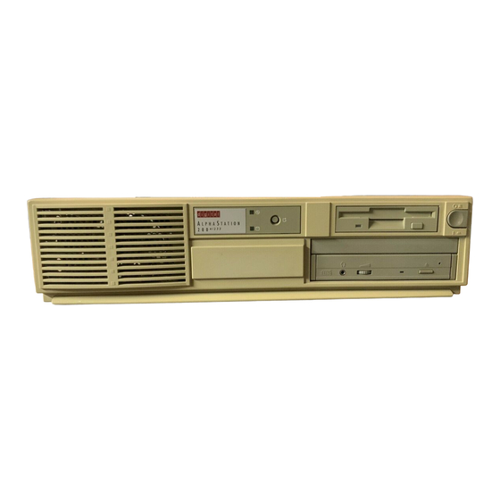
* Some versions of the AlphaStation 200 Series systems have two PCI/ISA slots. System Unit AlphaStation 200 Series System Desktop Enclosure The Digital AlphaStation 200 Series system's corporate slimline desktop low-profile enclosure houses the motherboard, I/O riser card, power supply, audio, and Ethernet options and internal peripherals. -
Page 21: Controls, Indicators, And Connectors
Figures 1-1 and 1-2 and Tables 1-2 and 1-3 show and describe the front and rear views, respectively, of the Digital AlphaStation 200 Series system. The motherboard includes eight diagnostic LEDs, which are visible through ports at the rear of the system. (These viewing ports are intended for diagnostic use by manufacturing, service personnel, and repair sites.) A stake-pin connector on the motherboard provides... - Page 22 AlphaStation System Descriptions Table 1-2. AlphaStation 200 Series Front Controls and Indicators Figure Legend Control or Indicator Function Power indicator Power. Lights when the system is on. Disk activity indicator Hard disk drive. Lights when a hard disk drive is in use. Reset button This button resets the system and causes the self test to run.
-
Page 23: Alphastation 200 Series Rear Connectors
AlphaStation System Descriptions Figure 1-2. AlphaStation 200 Series Rear Connectors Table 1-3. AlphaStation 200 Series Rear Connectors Figure Legend Connector Function Voltage selector switch Allows you to set your system to work with 115- Volt or 230-Volt AC power. Monitor power connector Use to connect a monitor to AC power. -
Page 24: Alphastation 400 Series System
AlphaStation System Descriptions Table 1-3. AlphaStation 200 Series Rear Connectors (continued) ISA expansion slot Used for half-size ISA expansion options only. PCI/ISA expansion slot Either a PCI or ISA option can use this slot. PCI expansion slot Used for PCI expansion options. (In earlier systems, this slot was a PCI/ISA combo slot. -
Page 25: Alphastation 400 Series Control And Indicators
AlphaStation System Descriptions MLO-012666 Figure 1-3. AlphaStation 400 Series Control and Indicators... -
Page 26: Alphastation 400 Series Controls And Indicators
AlphaStation System Descriptions Table 1-4. AlphaStation 400 Series Controls and Indicators Figure Legend Control or Indicator Function Drive bays Location of three upper 5.25-inch drive bays. Hard drive Location of hidden 3.5-inch drive bay. Floppy drive Location of 3.5-inch diskette drive. Floppy eject button Releases a 3.25-inch diskette from the floppy diskette drive. -
Page 27: Alphastation 400 Series Rear Connectors
AlphaStation System Descriptions MLO-012667 Figure 1-4. AlphaStation 400 Series Rear Connectors... -
Page 28: Alphastation 400 Series Rear Connectors
AlphaStation System Descriptions Table 1-5. AlphaStation 400 Series Rear Connectors Figure Legend Connector Function Voltage selector switch Allows you to set your system to work with 115- Volt or 230-Volt AC power. Monitor power connector Use to connect a monitor to AC power. If your monitor consumes more than 2 Amps at 115 Volts(1 Amp at 230 Volts), connect it directly to your wall outlet. -
Page 29: System Architecture
CPU's total address space and are separately decoded on the PCI bus using different values of the multifunction C/BE lines. Figure 1-5 shows the overall system architecture for the Digital AlphaStation 200 Series system. Figure 1-6 illustrates the overall system architecture for the Digital AlphaStation 400 Series system. -
Page 30: Alphastation 200 Series System Architecture
AlphaStation System Descriptions Figure 1-5. AlphaStation 200 Series System Architecture 1-12... -
Page 31: Cpu
The memory data path (to the secondary cache) is 128 bits wide, with an additional 4 bits of parity. The clock supplied to the CPU varies according to the particular system. In the 4/166 version of the Digital AlphaStation 200 Series system, the clock runs at 333 MHz; the 1-13... -
Page 32: Core Logic
AlphaStation System Descriptions CPU has divide-by-two logic that converts this external clock to 166 MHz internally. This relationship is also true for the other speed variations. Core Logic The supporting core logic provides a cache and memory controller, data path, and a PCI bus bridge. -
Page 33: Data Path
AlphaStation System Descriptions Data Path The data path portion of the core logic provides the path from the CPU to main memory and I/O. Two DECchip 21071-BA chips provide a 64-bit path to main memory. Included in the data path are: •... -
Page 34: Secondary Cache (Bcache)
AlphaStation System Descriptions – Sparse space for accesses with byte and word granularities and a maximum burst length of 2. – Dense space for burst lengths from 1 to 8 longwords on writes and a burst length of 2 longwords on reads. This region can be used for memory-like structures such as frame buffers, which require high bandwidth accesses. -
Page 35: Rom Interface
Both the Digital AlphaStation 200 and 400 Series systems have 8 diagnostic LEDs. The LEDs provide an indication of initialization and POST firmware progress and errors. In the Digital AlphaStation 200 Series system, the LEDs are mounted on the motherboard and are visible through slots in the back of the system enclosure. -
Page 36: Pci
AlphaStation System Descriptions for proper cooling are disrupted when the box is open, do not run the machine for an extended period with the side panel off. The PCI, a 33-MHz, 32-bit-wide multiplexed address/data bus, logically connects to all the I/O devices of the Digital AlphaStation 200 and 400 Series systems. -
Page 37: Isa Bridge
ISA addresses 3F8h through 3FFh and 2F8 through 2FFh. Keyboard/Mouse The Digital AlphaStation 200 Series and 400 Series systems include a standard Intel 8242 keyboard and mouse controller. The controller is accessed through the ISA bridge chip using addresses 060h and 064h. -
Page 38: Floppy Disk Controller (Fdc)
____________________________________________________________ Sound Card: Digital AlphaStation 200 Series System The Digital AlphaStation 200 Series system has a dedicated sound card, compatible with the Microsoft Windows Sound System. The sound card is connected to the ISA bus on a private connector. Neither the connector nor the sound card is ISA-standard. -
Page 39: Configuring Your Alphastation System
Configuring Your AlphaStation System Overview This chapter describes how to configure the Digital AlphaStation 200 and 400 Series systems, including the following topics: • System configurations • Memory • Mass storage expansion • PCI expansion • ISA expansion • Jumpers System Configurations You can configure your Digital AlphaStation 200 or 400 Series system in various ways. -
Page 40: Memory
Configuring Your AlphaStation System Table 2-1. Typical Digital AlphaStation System Configurations System Feature Description Sound card 16-bit audio with headphones and microphone Memory 32 MBytes (expandable to 192 MBytes) SCSI disk 1.05-GByte hard drive and CD-ROM drive Graphics option 8-plane, 2 Mpixel PCI (1280x1024 72 Hz) Monitor 15-inch color (optional in some packages) Ethernet... -
Page 41: Mass Storage Expansion
Mass Storage Expansion Internal Bay Availability: AlphaStation 200 Series Systems The Digital AlphaStation 200 Series system enclosure has four internal mass storage bays, as Figure 2-1 and Table 2-3 show. Notice that the floppy drive is connected to the FDC,... -
Page 42: Internal Bay Availability: Alphastation 400 Series Systems
Configuring Your AlphaStation System Figure 2-1. Internal Bays: AlphaStation 200 Series System Table 2-3. Description of the AlphaStation 200 Series Internal Bays Description The outer-bay lower area can hold one 5.25-inch half-height, front-accessible or nonaccessible, storage device. Typically, this bay is used for CD drives or tape drives. -
Page 43: Internal Bays - Alphastation 400 Series Systems
Configuring Your AlphaStation System Figure 2-2. Internal Bays - AlphaStation 400 Series Systems... -
Page 44: External Scsi Bus Expansion
SCSI operation or 4 meters (13.1 feet) for slow SCSI operation (5 Mbytes/sec). The amount of bus length inside the Digital AlphaStation 200 Series system is 1.4 meters (4.6 feet), which leaves 1.6 meters (5.25 feet) for external cabling and wiring in expansion enclosures if the bus is used in fast mode. -
Page 45: Alphastation 200 Series System Scsi Termination
Configuring Your AlphaStation System __________________________ NOTE ____________________________ Before powering on the system box, power on all external SCSI devices. ____________________________________________________________ AlphaStation 200 Series System SCSI Termination When you add external devices, the active terminator is automatically disabled (by sensing a conductor, on external connector pin 36, grounded by the external cable). You must insert a terminator in the expansion connector of the last expansion device. -
Page 46: Pci Expansion
Configuring Your AlphaStation System Table 2-5. AlphaStation 200 /400 Series System SCSI ID Assignments Device First hard disk Second hard disk CD-ROM Tape drive Host adapter PCI Expansion The AlphaStation 200 Series system has one PCI slot, one combination PCI/ISA slot, and one ISA slot on the riser card. -
Page 47: Pci Idsel Assignments
Configuring Your AlphaStation System Table 2-6. AlphaStation PCI Expansion Tasks Task Firmware Action Determine what PCI devices are present. Try to read the ID registers. When a device is located, determine its All 1's are written to its base address address space requirements. - Page 48 Configuring Your AlphaStation System __________________________NOTE ____________________________ Only a single IDSEL can be asserted in the configuration space address. ____________________________________________________________ Table 2-7 shows the relationship of the IDSEL bit, PCI base address, and CPU base address in the AlphaStation 200 Series and the AlphaStation 400 Series systems. Table 2-7.
-
Page 49: Ethernet Lan Controller Chip
Configuring Your AlphaStation System 1615 Device ID Vendor ID Command Status Class Code Rev ID BIST Header Latency Cache Type Timer Line Size 10-24h Base Address Registers 28-2Ch Reserved Expansion ROM Base Address Reserved 34-38h Figure 2-3. PCI Configuration Header Region Ethernet LAN Controller Chip The Digital DC21040 Ethernet LAN controller chip is mounted on the AlphaStation 200 Series system riser card. -
Page 50: Ethernet Identification Srom
Configuring Your AlphaStation System Ethernet Identification SROM A 32-byte EID SROM supplies the Ethernet address for the base network interface controller. Its data is accessed through the Ethernet controller. Writing to register CSR9 resets the pointer. Successive reads from CSR9 each return a byte of data in the low byte and increment the ROM pointer. -
Page 51: Procedure For Adding Isa Options
Configuring Your AlphaStation System To avoid operating system hangs, before you add ISA options to an OpenVMS or Digital UNIX system, use ISACFG to add the new options to the configuration database. If you add an option to the system without updating the database and you boot the operating system, you could cause the system to stall. -
Page 52: Jumpers
Configuring Your AlphaStation System Jumpers The Digital AlphaStation 200 Series and 400 Series systems use jumpers to control initialization, write enable flashROMs, and determine switch functions, clock speeds, and SCSI termination. This section describes the jumpers and their functions. AlphaStation 200 Series System Motherboard The Digital AlphaStation 200 Series system motherboard has several jumpers. -
Page 53: Alphastation 200 Series Motherboard Jumper Locations
Configuring Your AlphaStation System Table 2-9. AlphaStation 200 Series Motherboard Jumper Locations Jumper Setting Function Description (1 to 2) Mini-console. The position of J1 determines whether the SROM code goes to the SROM mini-console (for manufacturing use) or passes control to the next stage of (2 to 3) (D) Jump to main console. - Page 54 Configuring Your AlphaStation System Table 2-9. AlphaStation 200 Series Motherboard Jumper Locations (continued) Jumper Setting Function Description (1 to 2) Keyboard controller All are unused. (3 to 4) inputs. (5 to 6) (1 to 2) Disables sensing for J21 controls the automatic SCSI bus presence of external terminator.
-
Page 55: Sound Card
Configuring Your AlphaStation System Sound Card The Digital AlphaStation 200 Series system sound card uses three jumpers to control the motherboard beeps and the I/O address assignment. Figure 2-5 and Table 2-10 show these jumpers and describe their functions. Figure 2-5. AlphaStation 200 Series System Sound Card Jumpers Table 2-10. -
Page 56: Alphastation 400 Series System
Configuring Your AlphaStation System The J9 (1 to 4) jumper, timer counter enable (TCE), connects the timer-counter circuit from the motherboard to the mixer that drives the speaker header. Install this jumper to drive motherboard sound to the speaker connector. The motherboard sound is not mixed into the headphone output or the line out. -
Page 57: Cpu Module
Configuring Your AlphaStation System Table 2-11. AlphaStation 400 Series Motherboard Jumpers Jumper Setting Function Description 1 to 2 CMOS clear CMOS clear 2 only (D) Normal 1 to 2 Password clear Password clear (not used on the AlphaStation 400 2 only (D) Normal system) 1 to 2... -
Page 58: Alphastation 400 Series Pb50C-Ba Cpu Module Jumpers
Configuring Your AlphaStation System Figure 2-7. AlphaStation 400 Series PB50C-BA CPU Module Jumpers J3 J4 MLO-012677 2-20... -
Page 59: Alphastation 400 Series Pb50C-Ba Cpu Module Jumper Descriptions
Configuring Your AlphaStation System Table 2-12. AlphaStation 400 Series PB50C-BA CPU Module Jumper Descriptions Jumper Pins Function Description 1 to 2 Mini-console The position of J3 determines whether the SROM code goes to the SROM mini-console (for manufacturing use) or passes control to the next stage of initialization, the DROM code. -
Page 61: Addressing
Addressing Overview This chapter covers addressing for the Digital AlphaStation 200 and 400 Series systems, including the following topics: • Address diagram • Cacheable memory space • Noncacheable memory space • PCI sparse memory space • PCI dense memory space CPU-initiated accesses to the PCI bus can be either to PCI I/O space or to PCI memory space. -
Page 62: Address Diagram
Addressing Address Diagram The Digital AlphaStation 200 and 400 Series system CPUs use 34 bits to address physical address space. The physical address space is divided into the areas shown in Figure 3-1. 0 0000.0000 Cacheable Memory Space 1 0000.0000 Noncacheable Memory Space 2 0000.0000... -
Page 63: Cacheable Memory Space: 0 0000.0000-0 Ffff.ffff
Addressing Cacheable Memory Space: 0 0000.0000-0 FFFF.FFFF Memory addressing is set up during power-on initialization to start at address 0 0000.0000 and to occupy a contiguous address range. The highest memory address possible on a Digital AlphaStation 200 or 400 Series system is 0 17FF.FFFF (384 MBytes), as Figure 3- 2 shows. -
Page 64: Noncacheable Memory Space:1 0000.0000-1 Ffff.ffff
Addressing Noncacheable Memory Space:1 0000.0000-1 FFFF.FFFF Figure 3-3 shows the major areas of the noncacheable address space. The cache/memory controller responds to read/write accesses in the first two GByte of noncacheable space. (The Bcache is bypassed.) The other two GBytes of space are used for CSRs and PCI functions. -
Page 65: Cache/Memory Controller
Addressing Cache/Memory Controller The cache/memory controller portion of the core logic uses some of the space in the second two GBytes of noncacheable space for its CSRs. Table 3-2 shows the CSR names and addresses. For more information, refer to DECchip 21071/21072 Core Chip Sets Data Sheet, order number EK-N0648-72. - Page 66 Addressing Table 3-2. Cache Memory Controller Registers ( continued) Address Description 1 8000.0A60 Bank 3 configuration register 1 8000.0A80 Bank 4 configuration register 1 8000.0AA0 Bank 5 configuration register 1 8000.0AC0 Bank 6 configuration register 1 8000.0AE0 Bank 7 configuration register 1 8000.0B00 Bank 8 configuration register 1 8000.0C00...
-
Page 67: Pci Bridge Registers
Addressing PCI Bridge Registers Table 3-3 shows the PCI bridge register addresses that are located in the second half of the noncacheable space. Table 3-3. PCI Bridge Register Addresses Address Description 1 A000.0000 Diagnostic control and status register 1 A000.0020 PCI error address register 1 A000.0040 SysBUS error address register... -
Page 68: Pci Sparse I/O Space
Addressing Table 3-3. PCI Bridge Register Addresses ( continued) Address Description 1 A000.0340 TLB data 2 register 1 A000.0360 TLB data 3 register 1 A000.0380 TLB data 4 register 1 A000.03A0 TLB data 5 register 1 A000.03C0 TLB data 6 register 1 A000.03E0 TLB data 7 register 1 A000.0400... -
Page 69: Pci Sparse I/O Space Translation (Lower 256 Kbyte)
Addressing 33 32 31 30 29 28 27 26 25 24 23 22 08 07 06 05 04 03 1 1 1 0 0 0 0 0 0 0 Length in Bytes HAXR0 Longword Address 31 30 29 28 27 26 25 24 23 03 02 01 00 0 0 0 0 0 0 0... -
Page 70: Pci Sparse I/O Space Byte Selection
Addressing The address bit encoding for byte selection is shown in Table 3-4. Table 3-4. PCI Sparse I/O Space Byte Selection Transfer A<6:5> A<4:3> CBE#<3:0> AD<2> AD<1:0> Type 1110 A<7> Byte 1101 A<7> Byte 1011 A<7> Byte 0111 A<7> Byte 1100 A<7>... -
Page 71: Pci Sparse Address Space
Addressing Figure 3-6 shows some of the devices that are accessed through PCI sparse address space. Keyboard Cacheable Mouse Memory Space Noncacheable TOY Clock Memory Space SLU 2 Noncacheable Parallel Port Memory Space Sound Card Cache/Memory PCI Sparse Controller CSRs SLU 1 Memory Space PCI Bridge CSRs... -
Page 72: Embedded Isa Device Addresses
Addressing Embedded ISA Device Addresses Table 3-5 shows the ISA device addresses and the equivalent PCI and CPU addresses for the standard embedded ISA devices. Table 3-5. Embedded ISA Device Addresses Device/Register ISA Address PCI Address CPU Address Keyboard 0000.0060 1 C000.0C00 Mouse 0000.0064... - Page 73 Addressing Table 3-5. Embedded ISA Device Addresses ( continued ) Device/Register ISA Address PCI Address CPU Address Digital Output 03F2 0000.03F2 1 C000.7E40 Register Tape Drive 03F3 0000.03F3 1 C000.7E60 Register Main Status 03F4 0000.03F4 1 C000.7E80 Register Data Rate 03F4 0000.03F4 1 C000.7E80...
-
Page 74: Alphastation 200 Series System Sound Card
Addressing AlphaStation 200 Series System Sound Card Jumpers select the sound card I/O base address for the AlphaStation 200 Series system. Table 3-6 shows the four possible sound card I/O address and the PCI and CPU address for each one. The synthesizer portion of the sound card always uses addresses 388h - 38Bh. Table 3-6. -
Page 75: Configuration Cycles
Addressing Configuration Cycles Configuration cycles are generated on the PCI bus when accesses are made to CPU addresses 1 E000.0000 through 1 FFFF.FF80. The two low-order PCI address bits, AD<1:0>, are supplied from HAXR2<1:0>. The address bit encoding for byte selection is shown in Table 3-7. __________________________ NOTE ____________________________ PCI address bit AD<2>... -
Page 76: Pci Sparse Memory Space
Addressing PCI Sparse Memory Space The core logic generates PCI memory cycles for all accesses in the CPU address range 2 0000.0000 through 2 FFFF.FFFF as Figure 3-7 shows. 0 0000.0000 2 0000.0000 Cacheable Memory Space 1 0000.0000 Noncacheable Byte, Word Memory Space Tribyte, Longword, or Quadword... -
Page 77: Pci Memory Space Address Translation (Lower 16 Mbytes)
Addressing Table 3-8. PCI Sparse Memory Space Byte Selection Transfer A<6:5> A<4:3> CBE#<3:0> AD<2> Type 1110 A<7> Byte 1101 A<7> Byte 1011 A<7> Byte 0111 A<7> Byte 1100 A<7> Word 1001 A<7> Word 0011 A<7> Word 1000 A<7> Tri-byte 0001 A<7>... -
Page 78: Pci Memory Space Address Translation (Remaining 112 Mbytes)
Addressing 33 32 31 30 29 28 08 07 06 05 04 03 1 0 Nonzero Length in Bytes HAXR1<31:27> Byte Offset Longword Address (Refer to Table 3-8) 31 30 29 28 27 26 03 02 01 00 0 0 0 Figure 3-9. -
Page 79: Pci Dense Memory Space
Addressing PCI Dense Memory Space To access PCI dense memory space, use addresses 3 0000.0000 though 3 FFFF.FFFF in the CPU's address space, as Figure 3-10 shows. 0 0000.0000 3 0000.0000 Cacheable Memory Space 1 0000.0000 Noncacheable One-to-One Memory Space Mapping Between CPU and PCI Addresses... - Page 80 Addressing • Read prefetching is allowed in this space; extra reads have no side effects. The CPU does not specify a longword address on read transactions; it only specifies a quadword address. Therefore, reads in this space are always done as a quadword read with a burst length of two on the PCI.
-
Page 81: I/O Device View Of I/O Space
Addressing I/O Device View of I/O Space Figure 3-11 shows address space from the I/O perspective. Figure 3-11. Address Space from the I/O Perspective 3-21... -
Page 83: Overview
I/O Programming Overview This chapter covers unique areas of I/O programming for the Digital AlphaStation 200 and 400 Series systems, including: • Accessing flashbus devices • Keyboard and mouse controller • • Super I/O chip • Disabling interrupts Accessing Flashbus Devices On the Digital AlphaStation 200 and 400 Series systems, the flashROM, NVRAM, DROM, LEDs, and two jumpers reside on the flashbus. -
Page 84: Flashbus Index Register
I/O Programming 31 30 29 28 08 07 Unused Offset W Unused Figure 4-1. Flashbus Index Register Table 4-1. Flashbus Index Register Bit Descriptions Bits Function <31> Write harbinger: Set to 1 if flashbus write is intended. Set to 0 is flashbus read is intended. <30:29>... -
Page 85: Flashbus Offsets
I/O Programming Flashbus Offsets Table 4-3 lists the flashbus offsets for the Digital AlphaStation 200 and 400 Series systems. Table 4-3. Flashbus Device Offset Addresses Offset Address Access Device FlashROM 0 (optional) 00.0000 - 03.FFFF FlashROM 1 (optional) 04.0000 - 07.FFFF 08.0000 - 0B.FFFF FlashROM 2 (optional) FlashROM 3 (optional) -
Page 86: Keyboard And Mouse Controller
I/O Programming _________________________ NOTES ____________________________ The contents of the flashROM devices are changeable only when you have set the Write Enable jumper to the write enable position. When writing the flashROM memory, you must meet specific timing requirements by program delays and procedures. Refer to the appropriate flashROM specification for details. -
Page 87: Toy
<7:0>. The Digital AlphaStation 200 Series system includes a standard TOY clock that also has 114 bytes of battery-supported RAM. The chip is addressed as a device on the Utility Bus spawned by the ISA bridge chip. -
Page 88: Super I/O Chip
I/O Programming Super I/O Chip You can access the FDC through ISA addresses 3F0h through 3F7h. These addresses map into CPU sparse I/O addresses 1 C000.7E00 through 1 C000.7EE0. The PC87312 super I/O chip is set to its "PC/AT mode" by tying the IDENT pin high during power-on reset. -
Page 89: Dma
Overview This chapter includes information on ISA DMA channels for the Digital AlphaStation 200 and 400 Series systems. ISA DMA Channels The ISA interface uses eight DMA channels. DMA channel 4 cascades two four-channel DMA controllers, leaving only channels 0-3 and 5-7 available. Any DMA channel can be programmed for either 8- or 16-bit transfers. -
Page 90: Dma Channel Assignments
The DMA channels are assigned as Figure 5-1 shows. ISA Slot ISA Slot Floppy ISA Slot/ Parallel Port ISA Slot ISA Slot ISA Slot Figure 5-1. DMA Channel Assignments... -
Page 91: Hardware Interrupts
Hardware Interrupts Overview This chapter discusses Digital AlphaStation 200 and 400 Series systems' hardware interrupts, including the following topic areas: • Interrupts • Sources • Hardware reaction to errors Interrupts Interrupts from the various I/O components of the Digital AlphaStation 200 and 400 Series systems connect to the interrupt-controller section of the ISA bus bridge chip. -
Page 92: Irq0: Cpu Bus And Parity Errors
Hardware Exceptions and Interrupts Figure 6-1. Interrupt System Block Diagram The CPU has six interrupt inputs; five of these are used in the Digital AlphaStation 200 and 400 Series systems. All interrupt handling is performed in PALcode. Interrupt inputs are assigned as Table 6-1 shows. Table 6-1. -
Page 93: Irq2: Device Interrupts
Hardware Exceptions and Interrupts system by means of an interrupt through system control block (SCB) entry 660h (hexadecimal) or 670h. IRQ2: Device Interrupts When a device interrupt has been detected on CPU line IRQ2, the PALcode interrupt dispatcher must generate a PCI INTACK cycle. The PCI-ISA bridge chip sees this cycle and converts it into two cycles that freeze and then read the normal ISA-style interrupt priority encoders within the bridge chip. -
Page 94: Interrupt Inputs
Hardware Exceptions and Interrupts Interrupt Inputs The ISA bridge chip allows for 16 interrupt inputs; not all of these are external to then chip. Within the bridge chip, logic for two separate 8259 interrupt controllers are connected, with IRQ2 used to cascade the second controller. The controllers' priority, from highest to lowest, is 0-1, 8-15, 3-7. -
Page 95: Pci Interrupts
PCI interrupts from the PCI slots, plus the embedded SCSI and embedded Ethernet (Digital AlphaStation 200 Series system only) controllers are wire-ORed according to Table 6-3 and then brought to the four PCI interrupt inputs of the ISA bridge chip. These are logically routed to ISA IRQ lines. - Page 96 Hardware Exceptions and Interrupts Table 6-3. PCI Interrupt Assignments (continued) AlphaStation 400 Series System PIRQ PIRQ PIRQ PIRQ SCSI Slot 1, INTA Slot 1, INTB Slot 1, INTC Slot 1, INTD Slot 2, INTA Slot 2, INTB Slot 2, INTC Slot 2, INTD PIRQ0 = 1A | 1D | 2B | 3C PIRQ1 = 2A | 2D | 3B | 1C...
-
Page 97: System Power-Up And Initialization
System Power-Up and Initialization Overview This chapter explains system power-up and initialization for the Digital AlphaStation 200 and 400 Series systems, as the following topics outline: • Power-up sequence • Power supply and input power requirements • SROM • POST •... -
Page 98: Power Supply And Input Power Requirements
Power Supply and Input Power Requirements AlphaStation 200 Series System The 180-watt power supply for the Digital AlphaStation 200 Series system provides five DC voltages: +12-Volt, -12-Volt, +5-Volt, -5-Volt, and +3.3-Volt DC. These voltages are used by the various components within the system. Table 7-1 shows the AC input characteristics for the AlphaStation 200 Series system. -
Page 99: Alphastation 400 Series System Ac Input Characteristics
System Power-Up and Initialization Table 7-2. AlphaStation 400 Series System AC Input Characteristics Rated Voltage Range Maximum Range Rated Operating Input Frequency Current Range 100-Volt AC – 120-Volt AC 88-Volt AC – 132-Volt AC 47 Hz – 63 Hz 220-Volt AC – 240-Volt AC 176-Volt AC –... -
Page 101: Alphastation Firmware
AlphaStation Firmware Overview This chapter first explains how to use the firmware for the Digital AlphaStation 200 and 400 Series systems and then gives information on console commands, as the following topics outline: • Firmware components • Initialization • SROM features •... -
Page 102: Initialization
AlphaStation System Firmware Figure 8-1. AlphaStation Interface Relationships Initialization In a normal system power-up, firmware initialization occurs in the following sequence, assuming that (1) there are no hard errors and (2) the firmware jumpers are in the normal position, as listed below: 1. -
Page 103: Srom Features
AlphaStation System Firmware SROM Features The SROM code performs the following tasks: • Initializes the CPU • Sizes and configures tests and initializes memory • Tests and intializes the core logic • Loads the DROM code (or PALcode and console code if there is a DROM error) •... -
Page 104: Alphastation Series System Srom Code Actions
AlphaStation System Firmware Table 8-1. AlphaStation Series System SROM Code Actions Indicator Values Meaning Bit 7 Bit 0 Value l l l l l l l l Initialize CPU (BIU_CTL and ABOX registers initialized). l l l l l l l ¡ Initialize bank 8 logic. -
Page 105: Srom Beep Codes
AlphaStation System Firmware SROM Beep Codes Beep codes are heard from the system's speaker as three groups of beeps. For example, if the SROM code could not find any good memory, you would hear a 1-3-3 beep code (one beep, a pause, a burst of three beeps, a pause, and another burst of three beeps). Table 8-2 shows the SROM beep codes and their meanings for the Digital AlphaStation 200 and 400 Series systems. -
Page 106: Loading The Drom Code
AlphaStation System Firmware Loading the DROM code The SROM code loads the DROM code into memory and starts it. DROM LED Codes Table 8-3 shows the DROM POST steps and LED codes for the Digital AlphaStation 200 and 400 Series systems. Table 8-3. -
Page 107: Drom Beep Codes
AlphaStation System Firmware DROM Beep Codes Beep codes are heard from the system's speaker as three groups of beeps. For example, if the DROM code detected a realtime clock failure, you would hear a 1-2-1 beep code (one beep, a pause, a burst of two beeps, a pause, and one more singel beep). Table 8-4 shows the DROM beep codes and their meanings for the Digital AlphaStation 200 and 400 Series systems. -
Page 108: Possible Drom Code Actions
AlphaStation System Firmware DROM Code Entered Run POST Jumper = Load Floppy? Run Flash Loader Run Floppy Loader Floppy Boot Block Found? FlashROM Header Boot Floppy and Checksum Okay? Run DROM Mini-Console Run FlashROM Code (ARC or SRM) Figure 8-2. Possible DROM Code Actions... -
Page 109: Arc Console Features
AlphaStation System Firmware ARC Console Features The ARC console supports the Microsoft Windows NT operating system. The ARC console features an easy-to-use menu interface. The console includes: • Easy to read hardware configuration display. • Tools to manage the environment variables. •... -
Page 110: Srm Console Features
AlphaStation System Firmware SRM Console Features The SRM console supports the Digital UNIX and OpenVMS operating systems. The SRM console firmware provides the services and functionality commonly found in much more expensive machines. The console includes: • An operator interface •... - Page 111 AlphaStation System Firmware Table 8-6 SRM Console LED Codes (continued) Indicator Values Meaning Bit 7 Bit 0 Value l l l ¡ l l ¡ l SRM: DDB startup parts 1, 2, and 3, and locate HWRPB l l l ¡ l l ¡...
-
Page 112: Isa Configuration Utility
AlphaStation System Firmware ISA Configuration Utility ISA (industry-standard architecture) devices are not capable of being probed for configuration information by the Digital UNIX or OpenVMS operating systems. Therefore, you must enter ISA option information manually using the ISA configuration utility (ISACFG). Run this utility before installing a new ISA option module on a Digital AlphaStation 200 or 400 Series system running either the Digital UNIX or OpenVMS operating systems. - Page 113 AlphaStation System Firmware Table 8-7. SRM ISACFG Command Options (continued) Command Option Description -etyp <#> Defines an entry type for this entry. The # sign can be: 0 - Causes the entry to be deleted 1 - Single option 2 - Embedded multiport device 3 - Multiport option device -handle <string>...
-
Page 114: Adding Isa Options To Openvms And Digital Unix Systems
AlphaStation System Firmware Adding ISA Options to OpenVMS and Digital UNIX Systems When you add a supported ISA option to an AlphaStation 200 Series system running the OpenVMS or Digital UNIX operating system, perform the procedure shown in Table A-8. Table 8-8. -
Page 115: Srm Scripts
AlphaStation System Firmware >>>isacfg -slot 2 -etyp 1 -mk -iobase0 530 -iobase1 388 -irq0 9 -dmachan0 0 -dmachan1 1 -handle PCXBJ -enadev 1 Adding the FAX/MODEM option: >>>add_fax – or – the following two commands: >>>isacfg -mod -slot 0 -dev 3 -enadev 0 >>>isacfg -slot 4 -dev 0 -ml -handle COM4 -irq0 3 \ _>... -
Page 117: Fault Management
Fault Management Overview This chapter describes the decoding of error messages as produced by the AlphaStation Series system hardware. The AlphaStation 200 and 400 Series systems can run three different operating systems. This chapter describes the type of information that is available to the operating systems but does not cover the format of the error logger within the operating systems. -
Page 118: Control Signal Codes
Fault Management Control Signal Codes The AlphaStation 200 and 400 Series system control signals are used as communications and control between the major system components. The state of these signals are useful in determining the cause of an error. The following section lists the various control signals and their state interpretations. -
Page 119: Cycle Acknowledgment
Fault Management Cycle Acknowledgment The cAck_h lines connecting to the CPU signal cycle codes for completions of cycle transactions. Table 9-2 shows the cAck cycle code types. Table 9-2. PCI cAck Cycle Codes Code Cycle Type IDLE HARD_ERROR SOFT_ERROR - . This code is not used. -
Page 120: Summary Of Errors
Fault Management IO Commands The ioCmd lines are used by the PCI bridge chip to request an action by the cache and memory controller chip. Table 9-4 shows the PCI IO command codes. Table 9-4. PCI IO Commands Code CPU controls sysBus PCI Bridge controls Cycle Type sysBus Cycle Type... -
Page 121: Machine Check Id Codes
Fault Management Table 9-5. Machine Check ID Codes Code Description Recovery (hex) Action Tag Parity Error Fatal Tag Control Error Fatal Hardware Error Fatal Correctable ECC Not implemented Noncorrectable ECC Not implemented Unknown Error Fatal CackSoft Error Fatal BugCheck Fatal OS Bugcheck Fatal Dcache Parity Error... -
Page 122: Machine Check Logout Frame
Fault Management Machine Check Logout Frame The following is the format of the machine check logout frame built by the console firmware. All registers in Table 9-6 are CPU-specific registers. Table 9-6. Machine Check Logout Frame R | S | Bytes +000h System offset = [???h]... - Page 123 Fault Management Machine Check Logout Frame (continued) All registers on this page are system-specific registers for the Cache and Memory Controller chip (DECchip 21071-CA). COMA_GCR +1A0h COMA_EDSR +1A8h COMA_TER +1B0h COMA_ELAR +1B8h COMA_EHAR +1C0h COMA_LDLR +1C8h COMA_LDHR +1D0h COMA_BASE0 +1D8h COMA_BASE1 +1E0h COMA_BASE2...
- Page 124 Fault Management Machine Check Logout Frame (continued) All registers on this page are system-specific registers for the PCI Bridge chip (DECchip 21071-DA). EPIC_DCSR +208h EPIC_PEAR +210h EPIC_SEAR +218h EPIC_TBR1 +220h EPIC_TBR2 +228h EPIC_PBR1 +230h EPIC_PBR2 +238h EPIC_PMR1 +240h EPIC_PMR2 +248h EPIC_HARX1 +250h EPIC_HARX2...
-
Page 125: Error Registers
Fault Management Error Registers CPU internal errors are reported through the BIU_STAT register For CPU external interrupts, the PALcode parses the HIRR register in the CPU to determine the major error IRQ. Once the interrupt is determined, the PALcode parses one of the registers shown in Table 9-7 for detailed information on the cause of the error. -
Page 126: Error Format
Fault Management The operating system machine check handler is responsible for the following actions : • Creates kernel rvent jeader frame • Appends the machine check logout frame • Updates error log • Executes fault analysis using the saved machine check frame and context Error Format It is assumed that the user of this section will see the error as it is handed off to the operating system from the system PALcode. -
Page 127: Scb 660 Fatal Machine Checks
Fault Management SCB 660 Fatal Machine Checks Machine check codes vectoring through SCB 660 range from 0x201 to 0x20C . These machine checks cause an ERROR-IRQ interrupt on the CPU's IRQ0 line. This interrupt indicates that the PCI bridge chip detected an abnormal condition during a transaction. Machine Check Code 0x201, Retry Timeout Error See Table 9-9 for information on the retry timeout errors . -
Page 128: Machine Check Code 0X203, I/O Parity Error
Fault Management Machine Check Code 0x203, I/O Parity Error See Table 9-11 for information on machine check code 0x203, I/O parity errors . Table 9-11. Error: I/O Parity Error name: mchk$c_iope Register name: EPIC_DCSR bit<9> = 1 - iOPEI, /O Parity Error (MCLF+208) Bit description: An I/O parity error occurred in the data phase of an I/O R/W transaction. - Page 129 Fault Management Table 9-12. Target Abort (continued) Analysis Read 1 E007 0140 - SCSI Device Status Register (continued): If bit<15:11> != 0 - Determine the cause of abort. If bit<15> = 1 - SCSI detected parity error If bit<14> = 1 - SCSI signalled system error If bit<13>...
-
Page 130: Machine Check Code 0X205, No Device
Fault Management Machine Check Code 0x205, No Device See Table 9-13 for information on machine check code 0x205, No Device . Table 9-13. No Device Error name: mchk$c_ndev Register name: EPIC_DCSR bit<11> = 1 - ( MCLF+208 ) Bit description: DEVSEL# was not asserted in response to an I/O R/W initiated by the EPIC Chip. -
Page 131: Machine Check Code 0X207, Uncorrectable Memory Error
Fault Management Machine Check Code 0x207, Uncorrectable Memory Error See Table 9-15 for information on machine check code 0x207, uncorrectable memory errors . Table 9-15. Error: Uncorrectable Memory Error name: mchk$c_umrd Register name: EPIC_DCSR bit<13> = 1 - uMRD ( MCLF+208 ) Bit description: Uncorrectable Memory Read Data. -
Page 132: Machine Check Code 0X209, Memory Error
Fault Management Machine Check Code 0x209, Memory Error See Table 9-17 for information on machine check code 0x209, memory error . Table 9-17. Memory Error Error name: mchk$c_merr Register name: EPIC_DCSR bit<15> = 1 - mErr ( MCLF+208 ) Bit description: Memory Error. -
Page 133: Machine Check Code 0X20A, Bcache Tag Address Parity Error
Fault Management Machine Check Code 0x20A, Bcache Tag Address Parity Error See Table 9-18 for information on machine check code 0x20A, Bcache tag address parity error . Table 9-18. Bcache Tag Address Parity Error Error name: mchk$c_ctaperr Register name: COMA_EDSR bit<1> = 1 ( MCLF+1A8 ) Bit description: Bcache Tag Address Parity Error Indicates that a tag probe encountered bad parity in the tag address RAM. -
Page 134: Machine Check Code 0X20C, Nonexistent Memory Error
Fault Management Machine Check Code 0x20C, Nonexistent Memory Error See Table 9-20 for information on machine check code 0x20C, nonexistent memory error . Table 9-20. Nonexistent Memory Error Error name: mchk$c_nxmerr Register name: COMA_EDSR bit<3> = 1 - ( MCLF+1A8 ) Bit description: Nonexistent Memory Error. -
Page 135: Machine Check Code 0X80, Bcache Tag Parity Error
Fault Management Machine Check Code 0x80, Bcache Tag Parity Error See Table 9-22 for information on machine check code 0x80, Bcache tag parity error . Table 9-22. Bcache Tag Parity Error Error name: mchk$c_tperr Register name: BIU_STAT bit<3> = 1 ( MCLF+168 ) Bit description: A backup cache tag probe encountered bad parity in the tag address RAM Recovery:... -
Page 136: Machine Check Code 0X82, Bcache Tag Control Parity Error
Fault Management Machine Check Code 0x82, Bcache Tag Control Parity Error See Table 9-23 for information on machine check code 0x82, Bcache tag control parity error . Table 9-23. Bcache Tag Control Parity Error Error name: mchk$c_tcperr Register name: BIU_STAT bit<3> = 1 (MCLF+168) Bit description: A backup cache tag probe encountered bad parity in the tag control RAM. -
Page 137: Scb 670 Processor Fatal Machine Checks
Fault Management SCB 670 PROCESSOR FATAL MACHINE CHECKS Machine Check Code 0x84, Hard Error See Table 9-24 for information on machine check code 0x84, hard error . Table 9-24. Hard Error Error name: mchk$c_herr Register name: BIU_STAT bit<1> = 1 (MCLF+168) Bit description: Indicates an CPU external cycle was terminated with a HARD_ERROR on cAck_h pins. -
Page 138: Machine Check Code 0X88, Noncorrectable Ecc
Fault Management Machine Check Code 0x88, Noncorrectable ECC See Table 9-26 for information on machine check code 0x88, noncorrectable ECC . Table 9-26. Noncorrectable ECC Error name: mchk$c_ecc_nc Register name: This machine check is not implemented in the 21064 CPU chip. Bit description: Recovery: Not recoverable. -
Page 139: Machine Check Code 0X8C, Soft Error
Fault Management Machine Check Code 0x8C, Soft Error See Table 9-28 for information on machine check code 0x8C, soft error . Table 9-28. Soft Error Error name: mchk$c_Cacksoft Register name: BIU_STAT bit<2> = 1 (MCLF+168) Bit description: Indicates an CPU external cycle was terminated with a SOFT_ERROR on cAck_h pins. -
Page 140: Machine Check Code 0X90, Os Bugcheck
Fault Management Machine Check Code 0x90, OS Bugcheck See Table 9-30 for information on machine check code 0x90, OS bugcheck . Table 9-30. OS Bugcheck Error name: mchk$c_os_bugcheck Register name: Bit description: Recovery: Not recoverable. Analysis: Faulting FRU: Machine Check Code 0x92, Primary Cache Data Fill Error (Dcache) See Table 9-31 for information on machine check code 0x92, primary cache data fill error (Dcache) . -
Page 141: Machine Check Code 0X94, Primary Cache Data Fill Error (Icache)
Fault Management Machine Check Code 0x94, Primary Cache Data Fill Error (Icache) See Table 9-32 for information on machine check code 0x94, primary cache data fill error (Icache) . Table 9-32. Primary Cache Data Fill Error (Icache) Error name: mchk$c_icperr Register name: BIU_STAT bit<10>... -
Page 142: Additional Errors
Fault Management ADDITIONAL ERRORS The following error bits may be set but do not have an associated machine check code. Review of these need to be made in order to assure having determinate errors. Bcache Multiple Error See Table 9-34 for information on the Bcache multiple error . Table 9-34. -
Page 143: Primary Cache Multiple Error
Fault Management Primary Cache Multiple Error See Table 9-36 for information on the primary cache multiple error . Table 9-36. Primary Cache Multiple Error Error name: Register name: BIU_STAT bit<14> = 1 (MCLF+168) Bit description: Indicates that a primary cache fill operation resulted in parity error while bit<10 or 8>... -
Page 145: Connector And Cable Information
Internal cables AlphaStation 200 Series System Internal Connectors Motherboard This section describes the internal connectors on the Digital AlphaStation 200 Series system motherboard. Serial Diagnostic Port The serial diagnostic port, J7, on the motherboard is a 10-pin male connector. The port is designed to support system testing during manufacturing. -
Page 146: Speaker Connector
SROMCDAT Speaker Connector The Digital AlphaStation 200 Series system motherboard has a connector, J18, for the internal speaker. If the sound card is installed, the speaker is attached to the sound card directly and J18 is unused. Table 10-2 identifies the speaker connector pins and signals. -
Page 147: Floppy Disk Controller
Ground Sound Card Connector The Digital AlphaStation 200 Series system has a private 90-pin connector, J23, on the motherboard for a custom sound card. The connector is logically on the ISA bus, although neither the connector nor the sound card is ISA-standard. -
Page 148: Front-Panel Lights And Switches Connector
Connector and Cable Information Front-Panel Lights and Switches Connector The Digital AlphaStation 200 Series system control and indicator panel is connected to J5 on the motherboard. The front-panel board of the Digital AlphaStation 200 Series system includes two LEDs (power on and disk busy) and a reset switch. A short cable connects the front panel to the motherboard. -
Page 149: Internal Scsi Bus Connector J15
Connector and Cable Information Internal SCSI Bus Connector J15 The Digital AlphaStation 200 Series system has a 50-pin SCSI bus connector on the motherboard designed for SCSI devices mounted within the system enclosure. Table 10-5 identifies the internal SCSI bus connector's pins and signals. -
Page 150: Power Connectors
Ground Fan Connector The Digital AlphaStation 200 Series system may have either a 210-watt or a 180-watt power supply. In systems that have the the 210-watt supply, the system fan is powered directly from the power supply. In systems that have the 180-watt supply, the fan is connected to the J29 on the motherboard. -
Page 151: Sound Card
Ground -BUF_NET_ACTIVE_LED Ground +12 Volt Ground Sound Card The Digital AlphaStation 200 Series system sound card has three internal connectors (J5, J6, and J8), as Table 10-8 shows. Table 10-8. AlphaStation 200 Series System Sound Card Connectors Connector Type Connection... -
Page 152: Floppy
Connector and Cable Information Floppy Table 10-9 lists the signals and pins for the Digital AlphaStation system floppy device controller (FDC) connector pinouts. Table 10-9. Floppy Device Controller Connector Pinouts Signal Signal DENSEL Ground MTR3\ Ground DRATE0 Ground INDEX\ Ground MTR0\ Ground DR1\... -
Page 153: Cpu Module: Serial Diagnostic Port
Connector and Cable Information Table 10-10. AlphaStation 400 Series System Front-Panel Connector Pinouts (J31) Signal Ground Ground +5 Volt Open Reset switch input Turbo LED (STURBO L) Power-on LED (SPOWER H) Disk busy LED (HDACTIVE L) • Internal SCSI Bus •... -
Page 154: Pci Slots
Connector and Cable Information PCI Slots Notice that Table 10-12 does not match the pin numbering in the PCI specification. The position of the signals is the same, although the pin numbers are different. Table 10-12. PCI Slot Connector Pinouts Signal Signal Signal... - Page 155 Connector and Cable Information Table 10-12. PCI Slot Connector Pinouts (continued) Signal Signal Signal Signal AD30 AD31 CBE0# AD08 +3.3 Volt AD29 +3.3 Volt AD07 AD28 Ground AD06 +3.3 Volt AD26 AD27 AD04 AD05 Ground AD25 Ground AD03 AD24 +3.3 Volt AD02 Ground IDSEL...
-
Page 156: Isa Expansion Slots
Connector and Cable Information ISA Expansion Slots Table 10-13 lists the ISA slot connector pinouts for the Digital AlphaStation 200 and 400 Series systems. Table 10-13. ISA Slot Connector Pinouts Signal Signal IOCHK\ Ground SD07 RSTDRV SD06 SD05 IRQ9 SD04 -5 Volt SD03 DREQ2... - Page 157 Connector and Cable Information Table 10-13. ISA Slot Connector Pinouts (continued) Signal Signal SA06 IRQ3 SA05 DACK2\ SA04 SA03 BALE SA02 SA01 SA00 Ground SBHE\ MEMCS16\ LA23 IOCS16\ LA22 IRQ10 LA21 IRQ11 LA20 IRQ12 LA19 IRQ15 LA18 IRQ14 LA17 DACK0\ MRDC\ DREQ0 MWTC\...
-
Page 158: External Connectors
Connector and Cable Information External Connectors The external connectors of the Digital AlphaStation 200 Series systems allow for a number of cables and devices to be attached, as Figure 10-1 and Table 10-14 show. Figure 10-1. AlphaStation 200 Series System Rear Connectors Table 10-14. -
Page 159: Parallel Port
Connector and Cable Information Table 10-14. AlphaStation 200 Series System Rear Connectors (continued) Figure Connector Function Legend Sound card line in Brings audio signals into the card (for example, connector from a stereo amplifier). Sound card line out Routes audio signals to an external amplifier. connector Sound card headphone Connector for the headphones or amplified... -
Page 160: Alphastation 400 Series System Rear Connectors
Connector and Cable Information MLO-012667 Figure 10-2. AlphaStation 400 Series System Rear Connectors 10-16... -
Page 161: Alphastation 400 Series System Rear Connectors
Connector and Cable Information Table 10-15. AlphaStation 400 Series System Rear Connectors Figure Connector Function Legend Voltage selector switch Allows you to set your system to work with 115 or 230 Volt AC power. Monitor power connector Connects a monitor to AC power. If your monitor consumes more than 2 Amps at 115 Volt (1 Amp at 230 Volt), connect it directly to your wall outlet. -
Page 162: Alphastation 400 Series System External Connectors
Connector and Cable Information Table 10-16 shows the external cables for the AlphaStation 400 Series system. Table 10-16. AlphaStation 400 Series System External Connectors External Connector Purpose SCSI High-density, single-ended 50-pin shielded device connector. Keyboard Standard workstation keyboard connector. Mouse Standard PC mouse connector. -
Page 163: Parallel Port Connector Pinout
Connector and Cable Information Parallel Port Table 10-17 lists the signals and pin positions for Digital AlphaStation parallel port connector pinouts. Table 10-17. Parallel Port Connector Pinout Signal PSTRB\ PDAT0 PDAT1 PDAT2 PDAT3 PDAT4 PDAT5 PDAT6 PDAT7 PACK\ PBUSY SLCT PAUTOFD\ PERROR\ PINIT\... -
Page 164: Serial Line Units
Connector and Cable Information Serial Line Units COM1/2 Pinouts Table 10-18 lists the signals and pin positions for the Digital AlphaStation COM1 and Com2 connector pinouts. Table 10-18. COM1 and COM 2 Connector Pinouts Signal Ground SCSI The relative position of signals (Table 10-19) on the Digital AlphaStation Series system's internal and external connectors are the same;... -
Page 165: Connector Pinouts
Connector and Cable Information Table 10-19. SCSI Connector Pinouts Signal Internal External Signal Internal External DB0\ Ground DB1\ Ground DB2\ Ground DB3\ Ground DB4\ Ground DB5\ Ground DB6\ Ground DB7\ Ground DBP\ Ground Ground Ground Ground Ground Reserved Reserved TERMP Open Reserved Reserved... -
Page 166: Keyboard/Mouse
Connector and Cable Information Keyboard/Mouse Table 10-20 lists the signals and pin positions for the Digital AlphaStation Series system keyboard connector pinouts. Table 10-20. Keyboard Connector Pinouts Signal KBDATA Open Ground +5 Volt KBCLK Open Table 10-21 lists the signals and pin positions for the Digital AlphaStation Series system mouse connector pinouts. -
Page 167: Internal Cables
Sound Card The connectors for the Digital AlphaStation 200 Series system sound card are shown in Table 10-23 . Table 10-23. AlphaStation 200 Series System Sound Card Connectors... -
Page 168: Alphastation 400 Series System Internal Cables
Connector and Cable Information Table 10-23. AlphaStation 200 Series System Sound Card Connectors (continued) Connector Type Connection Unconnected Unconnected Ground 4-pin header Left channel in from CD-ROM Ground Ground Right channel in from CD-ROM Table 10-24 lists and describes the internal cables for the Digital AlphaStation 400 Series system. -
Page 169: Registers
The registers are organized by sections , as outlined below: • CPU registers. (Refer to DECchip 21064 and 21064A Microprocessor Hardware Reference Manual, order number EC-Q9ZUA-TE, Digital Equipment Corporation.) • Cache and memory control CSRs. (Refer to DECchip 21071/21072 Core Chip Sets Data Sheet, order number EC-N0648-72, Digital Equipment Corporation.) -
Page 170: Cpu Registers
HW_MFPR (Move From Processor Register) instructions. Refer to the DECchip 21064 and 21064A Microprocessor Hardware Reference Manual, order number EC-Q9ZUA-TE, Digital Equipment Corporation. Translation Buffer Tag (TB_TAG) Register The TB_TAG register is a write-only register that holds the tag for the next translation buffer update operation in the Instruction Translation Buffer or the Data Translation Buffer. -
Page 171: Instruction Translation Buffer Page Table Entry Temp (Itb_Pte_Temp) Register
AlphaStation System Registers Instruction Translation Buffer Page Table Entry Temp (ITB_PTE_TEMP) Register The ITB_PTE_TEMP register is a read-only holding register for ITB_PTE read data. 35 34 33 13 12 11 10 09 08 PFN<33:13> Exceptions Address (EXC_ADDR) Register The EXC_ADDR register is a read/write register used to restart the machine after exceptions or interrupts. -
Page 172: Processor Status (Ps) Register
AlphaStation System Registers Processor Status (PS) Register The PS register is a read/write register containing only the current mode bits of the architecturally defined PS. Write Format 05 04 03 02 Read Format 34 33 Exception Summary (EXC_SUM) Register The EXC_SUM register contains various types of arithmetic traps that have occurred since the last time the register was written to (cleared). -
Page 173: Software Interrupt Request Register (Sirr)
AlphaStation System Registers Software Interrupt Request Register (SIRR) The SIRR is a read/write register used to control software interrupt requests. Write Format: 33 32 SIRR <15:01> Read Format: 29 28 14 13 12 10 5 4 3 USEK C A S SIRR HIRR HIRR... -
Page 174: Software Interrupt Enable Register (Sier)
AlphaStation System Registers Software Interrupt Enable Register (SIER) The SIER is a read/write register that enables corresponding bits of the SIRR requesting interrupts. For Writes: SIER<15:01> For Reads: 3231302928 13 12 10 9 U S E SIRR HIER HIER A A A <15:01>... -
Page 175: Data Translation Buffer Page Table Entry Register (Dtb_Pte)
AlphaStation System Registers Data Translation Buffer Page Table Entry Register (DTB_PTE) The DTB_PTE register is a read/write register representing the 32-entry DTB. 63 53 52 32 31 PFN<33:13> Data Translation Buffer Page Table Entry Temporary (DTB_PTE_TEMP) Register The DTB_PTE_TEMP register is a read-only holding register for DTB_PTE read data. 34 33 03 02 00 PFN<33:13>... -
Page 176: Flush Instruction Cache Asm (Flush_Ic_Asm) Register
AlphaStation System Registers Flush Instruction Cache ASM (FLUSH_IC_ASM) Register The FLUSH_IC_ASM is a pseudo register. A write to this register invalidates all Icache blocks in which the ASM bit is clear. Abox Control Register The Abox control register is a write-only register. It is included only to show what it controls. -
Page 177: Cycle Counter Control (Cc_Ctl) Register
AlphaStation System Registers Cycle Counter Control (CC_CTL) Register The CC_CTL register is write-only. This register controls the CC register. ENABLE COUNTER Bus Interface Unit Control (BIU_CTL) Register The BIU_CTL register is a write-only register. It is included here only to show what it controls. -
Page 178: Bus Interface Unit Status (Biu_Stat) Register
AlphaStation System Registers Bus Interface Unit Status (BIU_STAT) Register The BIU_STAT register is a read-only register. When the BIU_HERR, BIU_SERR, BC_TPERR, or BC_TCPERR bit is set, the BIU_STAT<6:0> register bits are locked until the BIU_ADDR register is read. FILL FILL FILL FILL FILL... -
Page 179: Backup Cache Tag (Bc_Tag) Register
PCI bridge. Refer to DECchip 21071/21072 Core Chip Sets Data Sheet, order number EC-N0648-72, Digital Equipment Corporation. The Digital AlphaStation 200 and 400 Series systems use neither the video capabilities nor memory banks three through seven. Bank eight is used to access the flashbus. -
Page 180: General Control Register
AlphaStation System Registers General Control Register The general control register (1 8000.0000) contains status information that affects the major operational modes of the cache and memory control chip. 15 14 03 02 01 00 0 0 bc_BadAP bc_FrcP bc_FrcV bc_FrcD bc_FrcTag bc_IgnTag bc_LongWr bc_NoAlloc bc_EN wideMem 0 sysArb 0 Error and Diagnostic Status Register... -
Page 181: Tag Enable Register
AlphaStation System Registers Tag Enable Register The tag enable register is a read/write register (1 8000.0060) that indicates which bits of the cache tag are to be compared with sysAdr<33:5>. If a bit is 1, the corresponding bits in sysAdr<33:5> and tagAdr<31:17> are compared. If a bit is 0, there is no comparison of those bits and the tagAdr bit is assumed to be tied low on the module. -
Page 182: Ldxl High Address Register
AlphaStation System Registers LDxL High Address Register The LDx_L low address register (1 8000.00E0) stores the low order bits of the last locked address. Bits <12:0> represent sysAdr<33:21>. This register is read-only. Reserved ldxl_HAdr <33:21> Bankset 0-8 Base Address Registers Each memory bankset has a corresponding base register (Bank 0 Address: 1 8000 0800, Bank 1 Address: 1 8000 0820, Bank 2 Address: 1 8000 0840). -
Page 183: Pci Bus Bridge Csrs
AlphaStation System Registers PCI Bus Bridge CSRs The PCI bridge CSRs are 32-bits wide (longword) and addressed on cache-line boundaries (address <4:2> must be 0). Writes to read-only registers do not cause errors and are acknowledged as normal. Only zeroes should be written to unspecified bites within a CSR. -
Page 184: Translated Base Registers
AlphaStation System Registers Translated Base Registers The t_Base field of the translated base registers (1 and 2, 1 A000 00C0 and 1 A000 00E0) specify the base CPU address for either the: • Translated PCI address for the PCI target window (if scatter/gather is disabled). •... -
Page 185: Host Address Extension Register 1
AlphaStation System Registers Host Address Extension Register 1 The host address extension register 1 (HARX1) (1 A000 01A0) is used to generate AD<31:27> on CPU-initiated transactions that address PCI memory space. The eAddr<4:0> field is used as the upper five PCI address bits (AD<31:27>). The field is read/write. -
Page 186: Tlb Data Registers 0-7
PCI Bus Device Registers Ethernet Controller Registers Refer to DECchip 21040 Ethernet Controller Data Sheet , order number EC-N0752-72, Digital Equipment Corporation CSR0 - Bus Mode Register - offset 00h CSR1 - Transmit Poll Demand - offset 08h CSR2 - Receive Poll Demand - offset 10h... -
Page 187: Scsi Controller Registers
AlphaStation System Registers SCSI Controller Registers Table 11-1 shows the SCSI chip registers for the Digital AlphaStation 200 and 400 Series systems. Refer to NCR 53C810 PCI-SCSI I/O Processor Data Manual, NCR. Table 11-1. SCSI Chip Register Map Config SCNTL3 SCNTL2 SCNTL1 SCNTL0... -
Page 188: Isa Bus Device Registers
AlphaStation System Registers ISA Bus Device Registers Table 11-2 shows the ISA device addresses for the Digital AlphaStation Series systems. Table 11-2. ISA Device Addresses Device/Register ISA I/O CPU Sparse Addresses Addresses Addresses Keyboard/Mouse 060 – 0000.0060 1 C000.0C00 0000.0064 1 C000.0C80 TOY Clock 070 –... -
Page 189: Sound Card Registers
Notice that the Microsoft Sound System documents the ID and status register as follows, but the Digital AlphaStation 200 Series system sound card implements all DMA and interrupt channels. The ChannelAvail bit is zero when all DMA channels (0, 1, 3) and interrupt channels (7, 9, 10, 11) are available. -
Page 190: Audio Command Register
Disabled IRQ7 IRQ9 IRQ10 IRQ11 Reserved Reserved Reserved Table 11-5 shows the channel selections for the Digital AlphaStation 200 Series system's audio DMA. Table 11-5. AlphaStation 200 Series system Audio DMA Channel Selection DMASEL Play Channel Capture Channel Disabled Disabled... -
Page 191: Index
Index Index AlphaStation 400 Series System power supply, 7-2 210710-AA chipset, 1-11 LED code values, 8-9 ARC console, 2-12, 8-9 AUI (attachment unit interface), 10-6 AC input characteristics AlphaStation 200 Series system table, 7-2 Bridge chip, 1-11 AlphaStation 400 Series system Bridge registers table, 7-2 PCI, 3-7... - Page 192 Index Chip speaker TOY, 1-19 table, 10-2 Clock source jumper, 2-15 Console firmware, 2-8 Computer Control signal codes, 9-2 controls and indicators, 1-6 Controller figure, 1-6 Ethernet, 2-11 table, 1-6 keyboard and mouse, 1-19, 4-4 Configuration cycles, 2-9, 3-15 Controllers Configurations floppy disk memory, 2-1...
- Page 193 Index DECchip 21064, 1-1 primary cache multiple DECchip 21071-AA, 1-1 table, 9-27 Devices uncorrectable memory external, 2-6 0x207 PCI, 2-9 table, 9-15 peripheral, 2-6 Error format, 9-10 Diagnostic LEDs, 1-17 table, 9-10 Error messages channel assignments decoding, 9-1 figure, 5-2 Error registers, 9-9 error checking, 1-15 Errors...
- Page 194 Index Flashbus, 1-16 assignments Flashbus device table, 6-4 reading from, 4-4 Interval timer interrupt, 6-3 writing to, 4-3 Flashbus devices bridge chip, 1-19 access procedure, 4-3 expansion, 2-12 accessing, 4-1 slots, 1-18 Flashbus offsets ISA bus, 1-19 table, 4-3 ISA configuration (ISACFG) utility, 8-12 FlashROM memory, 1-17 ISA device addresses FlashROM write enable jumper, 2-15...
- Page 195 Index motherboard table, 9-18 figure, 2-18 0x80 table, 2-18 Bcache tag parity error clock source, 2-15 table, 9-19 flashROM write enable, 2-15 0x82 functions, 2-14 Bcache tag control parity error halt request, 2-15 table, 9-20 motherboard, 2-18 0x84 SCSI termination sensing, 2-16 hard error sound card, 2-17 table, 9-21...
- Page 196 Index Mass storage bays, 2-3 table, 2-10 figure, 2-3 PCI bridge table, 2-3 features, 1-15 MAU (media adapter unit), 1-19, 2-11, 10-6 PCI bus Memory access to, 3-1 cacheable, 3-3 PCI configuration figure, 3-3 figure, 2-10 flashROM, 1-17 PCI configuration cycle main, 1-16 table, 3-15 noncacheable, 3-4...
- Page 197 Index Peripheral devices, 1-11 bus interface unit address, 11-10 Pinouts bus interface unit control, 11-9 COM1/2 bus interface unit status, 11-10 table, 10-20 C_STAT, 11-9 connector, 10-21 cache status, 11-9 keyboard connector CC, 11-8 table, 10-22 CC_CTL, 11-9 mouse connector clear serial line interrupt, 11-3 table, 10-22 CPU, 11-2...
- Page 198 Index hardware interrupt request, 11-4 virtual address, 11-7 HIER, 11-5 Reset button, 1-8 HIRR, 11-4 Riser card, 1-18, 2-11 ICCSR, 11-2 ROM interface, 1-17 instruction cache, 11-2 instruction translation buffer ASM, 11-3 instruction translation buffer page table entry, Scatter/gather mapping, 1-15 11-2 SCSI, 1-18 instruction translation buffer page table entry...
- Page 199 Index ISACFG command, 8-12 figure, 1-11 SRM scripts, 8-15 AlphaStation 400 Series SROM figure, 1-11 beep codes System configurations, 2-1 table, 8-5 table, 2-1 code leaving, 8-5 features, 8-3 Tape drive LED code values, 8-3 FDC, 2-3 loading code, 8-3 SCSI, 2-3 Storage bays, 2-4 internal...
Need help?
Do you have a question about the Digital AlphaStation 200 Series and is the answer not in the manual?
Questions and answers