Table of Contents
Advertisement
Quick Links
Download this manual
See also:
Technical Information
Advertisement
Table of Contents
Troubleshooting

Related Manuals for Digital Equipment Digital AlphaStation 400 Series


Summary of Contents for Digital Equipment Digital AlphaStation 400 Series
-
Page 1: User Information
Digital AlphaStation™ 400 Series User Information Order Number: EK-PCDSA-UI. B01 Digital Equipment Corporation Maynard, Massachusetts... - Page 2 Digital Equipment Corporation. Digital Equipment Corporation assumes no responsibility for any errors that might appear in this document. The software, if any, described in this document is furnished under a license and may be used or copied only in accordance with the terms of such license.
- Page 3 FCC Information - Class B FCC ID: AO9-PB50 This device complies with Part 15 of the FCC rules. Operation is subject to the following conditions: (1) this device may not cause harmful interference, and (2) this device must accept any interference received, including interference that may cause undesired operation. This equipment has been tested and found to comply with the limits for a Class B digital device, pursuant to Part 15 of the FCC rules.
-
Page 5: Table Of Contents
Contents Preface Welcome to the Digital AlphaStation 400 Series System ............xiii Audience ..........................xiii Organization of the Information..................... xiv Conventions........................... xiv Abbreviations ......................... xv Special Notices........................xvii Additional Information Resources ..................xviii 1 Getting Started Introduction ...........................1-1 Before Starting Your System ....................1-2 Posture and Work Habits ....................1-2 Identifying the Correct AC Power Cord ................1-5... - Page 6 Contents Passwords........................1-13 2 System Overview Introduction........................... 2-1 Motherboard.......................... 2-1 PCI Architecture......................2-2 SCSI Controller ......................2-2 Keyboard..........................2-2 System Front View ........................ 2-4 System Rear View ......................... 2-6 3 Installing System Options Introduction........................... 3-1 Removing the Side Panels ..................... 3-1 System Unit Components ......................
- Page 7 Contents A Console Commands Introduction .......................... A-1 ARC Console........................A-1 Commands You Need to Know..................A-2 Display Hardware Configuration................A-2 Set Default Environment Variables ................. A-2 Set Default Configuration ..................A-2 Manage Boot Selection Menu ................. A-2 Machine Specific Setup................... A-3 Boot "boot selection identifier"...
- Page 8 Contents Moving Your System......................B-3 Packing Your System..................... B-3 Installing Your System at a New Location ..............B-3 C Technical Specifications Introduction.......................... C-1 System Specifications......................C-1 External System Connectors ....................C-3 Bidirectional Parallel Port Connector................C-3 Serial Port Connectors ....................C-4 Keyboard and Mouse Connectors...................
- Page 9 Contents Equipment Log ........................G-1 Index Figures Digital AlphaStation 400 Series System ..............1-1 Recommendations for Posture and Work Habits............1-3 System Airflow ......................1-6 Voltage Selector Switch .....................1-7 Connecting Cables and Power Cords ................1-8 Starting Your System ....................1-9 Keyboard Layout......................2-3 Front Controls and Indicators ..................2-4 Rear Connectors......................2-6...
- Page 10 Contents System Troubleshooting..................... 4-2 Disk Drive Troubleshooting ..................4-6 Monitor Troubleshooting.................... 4-6 Error Beep Codes....................... 4-7 LED Codes ........................ 4-8 SRM Console Conventions..................A-5 SRM Console Special Characters ................A-6 SRM Boot Command Options................... A-7 SRM Boot Command Examples................A-8 SRM Set Command Options ..................
-
Page 11: Preface
AlphaStation 400 Series system. You also can find general system information such as console commands and system care here. Audience If you are operating, configuring, or adding options to the Digital AlphaStation 400 Series system, the information included here is helpful to you. -
Page 12: Organization Of The Information
Preface Organization of the Information This information for users covers the following topics (see the Table of Contents for a detailed listing): • Chapter 1, Getting Started. Installing, starting, restarting, and turning off the system • Chapter 2, System Overview. Motherboard, keyboard, system controls, indicators, ports, and connections •... -
Page 13: Abbreviations
Preface Abbreviations This guide uses the following abbreviations: Abbreviation Meaning Advanced RISC Computing (the Windows NT Console). Compact disc. CD-ROM Compact disc read only memory. Central processing unit. Direct memory access. DRAM Dynamic random access memory. DROM Diagnostic read only memory. File allocation table. - Page 14 Preface (continued) Light-emitting diode. Media Adapter Unit. An Mb suffix to a numerical value indicates size in megabits (for example, 10 Mb). A megabit equals 1,048,576 bits. A MB suffix to a numerical value indicates size in megabytes (for example, 550 MB). A megabyte equals 1,048,576 bytes. Megahertz.
-
Page 15: Special Notices
Preface Special Notices This guide uses four kinds of notices to emphasize specific information. ________________________ WARNING __________________________ A WARNING indicates the presence of a hazard that can cause personal injury. ____________________________________________________________ ________________________ CAUTION __________________________ A CAUTION indicates the presence of a hazard that can cause damage to hardware or that might corrupt software. -
Page 16: Additional Information Resources
You may wish to consult the following information resources on your Digital AlphaStation 400 Series system: • Digital AlphaStation™ 400 Series Installation Information (order number EK- PCDSA-II) presents a graphical overview of the Digital AlphaStation 400 Series installation. • Digital AlphaStation™ 200/400 Series Technical Information (order number EK- PCDSA-TI). -
Page 17: Getting Started
Getting Started Introduction Your Digital AlphaStation 400 Series system is a high-performance computer that uses the latest microprocessor technology. The system can stand alone or function as a client in an office network environment. This chapter describes how to start, install, restart, and turn off your Digital AlphaStation 400 Series system. -
Page 18: Before Starting Your System
Getting Started Before Starting Your System Before you start your system, perform the following steps: 1. Read and understand the information supplied with your system. 2. Select a well-ventilated site near a grounded power outlet and away from sources of excessive heat. -
Page 19: Recommendations For Posture And Work Habits
Getting Started MLO-011325 Figure 1-2. Recommendations for Posture and Work Habits Table 1-1. Recommendations for Posture and Work Habits Adjust To allow the following conditions Chair 1. Feet are flat on the floor. 2. Legs are vertical and form a right angle to the floor. 3. - Page 20 Getting Started Table 1-1. Recommendations for Posture and Work Habits ( continued ) Adjust To allow the following conditions Head 7. Avoid neck strain. Your head should incline downward, but no more than 15 to 20 degrees. Monitor 8. No higher than the level of your eyes and at the correct distance for your vision.
-
Page 21: Identifying The Correct Ac Power Cord
Getting Started Identifying the Correct AC Power Cord Your Digital AlphaStation 400 Series system came with the proper AC power cord. As there are variations from one country to another, and systems may be moved, please inspect your power cord to ensure it is the correct one for your country or region. If you are not sure that the supplied AC power cord is correct, contact your authorized Digital service representative before you use it. -
Page 22: Installing Your System
Getting Started Installing Your System The Digital AlphaStation 400 Series system Installation Information you received with your system graphically outlines the steps to follow in installing your system. _______________________ CAUTIONS __________________________ 1. To ensure that your system is properly cooled, make sure that air can freely flow into the front and out of the rear of the system unit. -
Page 23: Connecting System Parts
Getting Started Connecting System Parts To connect the components of your Digital AlphaStation 400 Series system, perform the following steps: 1. Confirm that the voltage selector switch matches your local voltage (either 115 V or 230 V), as Figure 1-4 shows. -
Page 24: Connecting Cables And Power Cords
Getting Started 3. Connect the mouse, keyboard, video cable, and power cords to the system components, as Figure 1-5 shows. ________________________ CAUTION___________________________ The system auxiliary AC outlet is limited to 2 Amps at 115 Volts (1 Amp at 230 Volts). Plug higher-amperage video monitors into a wall receptacle. ____________________________________________________________ MLO-012664 Figure 1-5. -
Page 25: Network Connection
Getting Started Network Connection If you ordered a system with an optional network module, connect your network interface cable to the appropriate port on your network module. Using the console software, you must select which of the two network ports will be used. See Appendix A, Console Commands, for detailed information. -
Page 26: Preloaded Operating System Software
If you ordered a system with the Microsoft Windows NT Workstation operating system, you will see the following display after power-on and initialization: ARC Multiboot Alpha AXP Version 3.5-13 Copyright (c) 1993 Microsoft Corporation Copyright (c) 1993 Digital Equipment Corporation Boot menu: Boot Windows NT Boot an alternate operating system Run a program Supplementary menu... -
Page 27: Openvms
Getting Started OpenVMS If you are using the OpenVMS operating system, you will either see a >>> prompt (if auto_action is set to Halt) or the system will proceed to boot OpenVMS (if auto_action is set to Boot) when you power on your system. For more information, refer to your operating system documentation. -
Page 28: Turning Off Your System
Getting Started Turning Off Your System Before turning off your system, make sure to save and close all open files. If you turn the system off without saving and closing files, you might lose some or all of your work. Perform the following steps to turn off your system: 1. -
Page 29: Computer Security
Chassis Lock To avoid theft of internal components, your Digital AlphaStation 400 Series system comes with a chassis key lock, which is located on the back of your system box. When this lock is in the locked position, no one else can open the system box. Store the key in a safe place. -
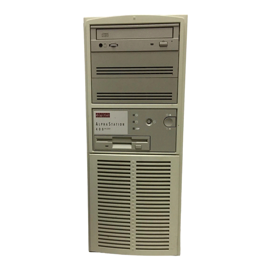
Page 31: System Overview
Motherboard Your Digital AlphaStation 400 Series system uses high-performance Alpha architecture CPU modules. For information on CPU modules, see the Digital AlphaStation 400 Series CPU Module Information. The system box has the following features: •... -
Page 32: Pci Architecture
PCI-to-ISA bridge capability that allows you to use commonly available ISA options. SCSI Controller The Digital AlphaStation 400 Series system uses a PCI-based embedded SCSI-2 controller that controls up to seven SCSI peripherals such as hard disk drives, CD-ROM (compact disc read only memory) drives, and tape drives. -
Page 33: Keyboard Layout
System Components Figure 2-1. Keyboard Layout Table 2-1. Key Groups and Functions Figure Key, Key Group Function Legend Escape key This key is program specific. Its function is determined by the installed application software. Function key group These keys are program specific. Their functions are determined by the installed application software. -
Page 34: System Front View
System Components System Front View Figure 2-2 is a front view of the system showing the location of the controls and indicators. Table 2-2 describes these items. MLO-012666 Figure 2-2. Front Controls and Indicators... -
Page 35: Front Controls And Indicators
System Components Table 2-2. Front Controls and Indicators Figure Control or Indicator Function Legend Drive bays Location of three upper 5¼-inch drive bays. Hard drive Location of hidden 3½-inch drive bay. Floppy drive Location of 3½-inch diskette drive. Floppy eject button Releases a 3½-inch diskette from the floppy diskette drive. -
Page 36: System Rear View
System Components System Rear View Figure 2-3 shows the rear connectors and lock. Table 2-3 lists the rear connectors and lock and describes their functions. MLO-012667 Figure 2-3. Rear Connectors... -
Page 37: Rear Connectors
System Components Table 2-3. Rear Connectors Figure Connector Function Legend Voltage selector switch Allows you to set your system to work with 115 or 230 V AC power. Monitor power connector Connects a monitor to AC power. If your monitor consumes more than 2 Amps at 115 V (1 Amp at 230 V), connect it directly to your wall outlet. -
Page 39: Installing System Options
Installing System Options Introduction This chapter explains how to install optional memory, expansion boards, and drives inside your Digital AlphaStation 400 Series system. Removing the Side Panels To remove the side panels, perform the following steps: 1. Turn off your system and all peripheral devices. -
Page 40: Unlocking And Removing Left Side Panel
Expanding Your System __________________________NOTE ____________________________ If you are installing or removing drives, you must remove both side panels. Otherwise, remove only the left side panel. ____________________________________________________________ MLO-012678 Figure 3-1. Unlocking and Removing Left Side Panel... -
Page 41: System Unit Components
Expanding Your System System Unit Components Figure 3-2 shows the location of the Digital AlphaStation 400 Series system unit components. Table 3-1 lists the system unit components. MLO-012669 Figure 3-2. System Unit Components Table 3-1. System Unit Components Figure Component... -
Page 42: Motherboard
Expanding Your System Motherboard Figure 3-3 shows the location of the motherboard components. Table 3-2 lists the motherboard components. MLO-012668 Figure 3-3. Motherboard Components... -
Page 43: Motherboard Components
Expanding Your System Table 3-2. Motherboard Components Figure Components Legend ISA expansion slots Combination PCI and ISA expansion slot PCI expansion slots External SCSI connector and bidirectional parallel port Power connector (+3.3 V) Serial ports Mouse and keyboard connectors FDC connector Internal SCSI connector Unused Power connector (+5 V) -
Page 44: Installing Additional System Memory
Expanding Your System Installing Additional System Memory Adding more memory allows your system to run larger, more memory-intensive software more quickly. You can increase your system's memory up to 192 MB. You can add 16-MB, 32-MB, or 64-MB memory options. These memory options are pairs of single in-line memory modules (SIMMs): a 16-MB option consisting of two 8-MB SIMMs, a 32-MB option consisting of two 16-MB SIMMs, or a 64-MB option consisting of two 32-MB SIMMs. -
Page 45: Adding Memory Modules
Expanding Your System Adding Memory Modules To add a pair of memory modules (SIMMs), perform the following steps: 1. Turn off your system. Disconnect any external devices and unplug the power cord from the wall outlet. Unplug the power cord and monitor cord from the back of the system unit. -
Page 46: Installing Expansion Boards
Expanding Your System Installing Expansion Boards The Digital AlphaStation 400 Series system features two PCI slots, three ISA slots, and one combination PCI and ISA slot. __________________________NOTE ____________________________ The SRM console for DEC OSF/1 and OpenVMS systems assigns available IRQs to PCI devices. IRQs are considered available if they are not assigned to ISA devices in the console's configuration database. -
Page 47: Installing An Expansion Board
Expanding Your System MLO-012671 Figure 3-6. Installing an Expansion Board 5. Replace the screw to secure the module. 6. Replace and lock the left side panel. 7. Connect the power cord and monitor cord to the back of the system unit. Connect any external devices and plug the power cord into the wall outlet. -
Page 48: Adding Mass Storage Devices
Lower drive bay area. This area has a drive bay assembly that holds a 3.5-inch floppy diskette drive (standard on all Digital AlphaStation 400 Series systems) and one hidden (nonaccessible from the front) 3.5-inch half-height device. This hidden bay is typically used for mounting the system's primary hard disk drive. -
Page 49: Scsi Termination
Host adapter (SCSI controller) SCSI Termination The Digital AlphaStation 400 Series system has a built-in SCSI bus that can be connected to both internal (inside the system box) and external SCSI peripherals. Termination is required at both the internal and external ends. -
Page 50: Installing Devices In The Upper Drive Bay Area
Expanding Your System Installing Devices in the Upper Drive Bay Area To install a device in the upper drive bay area, perform the following steps: 1. Turn off your system and unlock and remove the side panels, as described earlier in this chapter. -
Page 51: Removing The Metal Plate
Expanding Your System MLO-012893 Figure 3-8. Removing the Metal Plate 5. If you are installing a 3.5-inch device, add the 3.5- to 5.25-inch exchange brackets, as Figure 3-9 shows. Fasten the drive with the screws provided. Figure 3-9. Exchange Bracket Mounting 3-13... -
Page 52: Inserting A Device Into The Upper Drive Bay
Expanding Your System 6. Insert the new device into the drive bay from the front (Figure 3-10). 7. Secure the device with two screws on each side. Use the three front mounting holes as follows: H for hard drive; T for tape drive; and F for floppy or CD drive. MLO-012673 Figure 3-10. -
Page 53: Scsi And Fdc Cable Configuration
Expanding Your System Figure 3-11. SCSI and FDC Cable Configuration 3-15... -
Page 54: Power Cable Configuration
Expanding Your System 9. Connect a power cable to the device. Figure 3-12 shows the cables from the power supply. MLO-012679 Figure 3-12. Power Cable Configuration 10. Replace the metal plate that you removed in step 4. 11. Replace and lock the side panels. 12. -
Page 55: Installing Devices In The Lower Drive Bay Area
Expanding Your System Installing Devices in the Lower Drive Bay Area The lower drive bay area holds two 3.5-inch devices, a diskette drive, and, typically, a hard disk drive. To upgrade the devices in the lower drive bay area, you must remove the entire drive bay assembly from your system and then remove the devices from the assembly and install the new devices. -
Page 56: Removing The Lower Drive Bay Assembly
Expanding Your System MLO-012675 Figure 3-13. Removing the Lower Drive Bay Assembly 3-18... -
Page 57: Removing The Lower Drive Bay Devices
Expanding Your System 5. Remove a device by removing the screws on the side and sliding the device out of the lower bay assembly (Figure 3-14). Figure 3-14. Removing the Lower Drive Bay Devices 6. Slide the drive into the drive bay assembly and secure it with screws. ________________________ CAUTION __________________________ Be sure to use the screws that came with the drive. -
Page 59: Troubleshooting
Refer to the documentation supplied with additional options if you are experiencing problems with specific options that you have installed. Initial Troubleshooting Follow these general procedures to troubleshoot your Digital AlphaStation 400 Series system initially: 1. Check that the power indicators are on and that the fan is running. -
Page 60: Equipment Log
Troubleshooting Equipment Log For your convenience, Appendix G, Equipment Log, includes a form on which you can record all model numbers and serial numbers of your hardware components (system unit, monitor, keyboard, and mouse) and system hardware configuration information (CPU, memory size, drive size, ports, and so on). - Page 61 Troubleshooting Table 4-1. System Troubleshooting (continued) Problem Possible Cause Action System does not boot. Operating system Install the appropriate operating software is not installed system. on the hard disk drive. System cannot find the Check the system configuration for boot device. correct device parameters.
- Page 62 Troubleshooting Table 4-1. System Troubleshooting (continued) Problem Possible Cause Action System does not boot. Environment variables Windows NT: (continued) incorrectly set From the Boot menu, select (continued). Supplementary menu..., then select Setup the system..., then select Set default environment variables. (Refer to Appendix A, Console Commands.) Hard disk drive is not...
- Page 63 Troubleshooting Table 4-1. System Troubleshooting (continued) Problem Possible Cause Action No response to keyboard Keyboard is password Enter the keyboard password, if commands. protected. supported by your operating system. Keyboard is not connected. Connect the keyboard to the keyboard port. Keyboard is connected to Connect the keyboard to the the mouse port.
-
Page 64: Disk Drive Troubleshooting
No power at wall outlet. Use another outlet. Power indicator is Contact your service representative defective. or Digital Equipment Corporation. Distorted, rolling, or Monitor incorrectly Adjust accordingly. flickering screen display, adjusted. or wrong/uneven color. -
Page 65: Error Beep Codes
Your system contains eight diagnostic LED indicators located on the CPU module. The LEDs indicate errors that occur during system initialization and power-on self test (POST). Refer to the Digital AlphaStation 400 Series CPU Module Information for the locations of the LEDs. -
Page 66: Interpreting The Led Indicator Values
Troubleshooting Interpreting the LED Indicator Values Table 4-5 lists the LED indicator values and their meanings. The meanings are valid when the LEDs have stopped sequencing through tests due to an error condition. Table 4-5. LED Codes Indicator Values Meaning Bit 7 Bit 0 Value... -
Page 67: A Console Commands
ARC Console The ARC console supports the use of the Microsoft Windows NT Workstation operating system. The ARC console uses a menu interface. When a Digital AlphaStation 400 Series system is powered on, initialization is performed. During initialization, the firmware checks the information stored in the nonvolatile memory. -
Page 68: Commands You Need To Know
Console Commands Commands You Need to Know Display Hardware Configuration The Display hardware configuration command is located in the Supplementary menu. Use this command to display information about: • Devices that were detected (and are supported) by the ARC console •... -
Page 69: Machine Specific Setup
Console Commands • Operating system root directory. • Name (identifier) for this boot selection. • Whether or not the debugger should be initialized at boot time. After you have added a boot selection, use the Check boot selections command to perform verification testing of the selections. -
Page 70: Install Windows Nt From Cd-Rom
Console Commands Install Windows NT from CD-ROM The Install Windows NT from CD-ROM command is located in the Supplementary menu. You must put the Microsoft Windows NT Workstation CD (compact disc) into the CD drive before selecting this command. Switch to OpenVMS or OSF Console The Switch to OpenVMS or OSF console command is located in the Setup menu. -
Page 71: Srm Console
Console Commands SRM Console The SRM console supports the OpenVMS and DEC OSF/1 operating systems. The SRM console offers many different commands. For a complete list of SRM commands, type help at the SRM prompt (>>>). This section describes environment variables and the following commands: •... -
Page 72: Srm Console Special Characters
Console Commands SRM Console Special Characters Table A-2 lists console special characters and their functions. Table A-2. SRM Console Special Characters Character/Key(s) Function Return Terminates command line input. ß Backspace Deletes the previously typed character. [Ctrl]+[A] Toggles insert/overstrike mode. (Overstrike is the default.) á... -
Page 73: Boot Command
Console Commands Boot Command The boot command performs the following functions: • Initializes the processor • Loads a program image from the specified boot device • Transfers control to the loaded image The syntax of the boot command is shown below: boot [-file <filename>] [-flags <longword>[,<longword>]] [-protocols <enet_protocol>] [-halt] [<boot_device>] The boot command options are described in Table A-3. -
Page 74: Boot Command Examples
Console Commands Boot Command Examples Table A-4 shows boot command examples and their descriptions. Table A-4. SRM Boot Command Examples Command Description >>>boot Boots the system from the default boot device. Boots the system from Ethernet port ewa0. >>>boot ewa0 >>>boot -file dec2.sys mke0 Boots the file named dec2.sys from Ethernet port mke0. -
Page 75: Set Command
Console Commands Set Command The set command sets or modifies the value of an environment variable. Environment variables pass configuration information between the console and the operating system. The syntax of the set command is shown below: set <envar> <value> [-default] [-integer] [-string] The set command options are described in Table A-5. -
Page 76: Show Command
Console Commands Show Command The show command displays the current value of a specified environment variable. The show command also displays information about the system, according to the arguments entered. The syntax of the show command is shown below: show [{config, device, hwrpb, memory, pal, version, <envar>...}] The show command options are described in Table A-7. -
Page 77: Show Command Examples
Console Commands Show Command Examples Table A-8 lists show command examples and their descriptions. Table A-8. SRM Show Command Examples Command Description Lists device information such >>>show device as system designation, drive dka0.0.0.6.0 DKA0 RZ26L 441A model, or Ethernet address. dka400.4.0.6.0 DKA400 RRD43 3213 dva0.0.0.0.1... -
Page 78: Examine Command
Console Commands Examine Command The examine command displays the contents of an address you specify. The address can be a memory location, register, device, or file. The syntax of the examine command is shown below: examine [-{b,w,l,q,o,h,d}] [-{physical, virtual, gpr, fpr, ipr}] [-n <count>] [-s <step>] [<device>:]<address>... -
Page 79: Examine Command Examples
Console Commands Examine Command Examples Table A-10 shows examine command examples and their descriptions. Table A-10. SRM Examine Command Examples Command Description >>>e r0 Examines R0 using a symbolic address. gpr: 0 (R0) 0000000000000002 Examines R0 using address space. >>>e -g 0 gpr: 0 (R0) 0000000000000002... -
Page 80: Deposit Command
Console Commands Deposit Command The deposit command writes data to an address that you specify. The address can be a memory location, register, device, or file. The syntax of the deposit command is shown below: deposit [-{b,w,l,q,o,h}] [-{physical,virtual,gpr,fpr,ipr}] [-n <count>] [-s <step>] [<device>:]<address> <data> The deposit command options are described in Table A-11. -
Page 81: Deposit Command Examples
Console Commands Table A-11. SRM Deposit Command Options (continued) Command Option Description <address> An address that specifies the offset within a device into which data is deposited. The address can also be any legal symbolic address. Valid symbolic addresses are: •... -
Page 82: Environment Variables
Console Commands Environment Variables Table A-13 shows selected environment variables and their descriptions (for a complete list, type show * at the SRM prompt). Table A-13. SRM Environment Variables Variable Description auto_action Sets/shows the console action following an error, halt, or power-up. The action can be halt, boot, or restart. -
Page 83: Isa Configuration Utility
AlphaStation 400 Series system running either the DEC OSF/1 or OpenVMS operating systems. The Digital AlphaStation 400 Series system has five IRQ levels available for ISA and PCI expansion (5, 9, 10, 14, and 15). Prior to adding an ISA device, you must use ISACFG to assign an IRQ to the device. - Page 84 Console Commands Table A-14. SRM ISACFG Command Options (continued) Command Option Description -enadev <#> Allows you to specify whether an entry is enabled or disabled. Disabled devices are not used in resource allocation calculations. The possible values are: 0 - No (disabled) 1 - Yes (enabled) -etyp <#>...
-
Page 85: Adding Isa Options To Openvms And Dec Osf/1 Systems
Console Commands Adding ISA Options to OpenVMS and DEC OSF/1 Systems When you add a supported ISA option to an AlphaStation 400 Series system running the OpenVMS or DEC OSF/1 operating system, perform the procedure in Table A-15. Table A-15. Adding Options to OpenVMS or DEC OSF/1 Systems Step Action Result or Next Step... -
Page 86: Isacfg Command Examples
Console Commands ISACFG Command Examples This section shows examples of ISACFG commands you use to enter the DE205, sound card, and FAX/MODEM options into the configuration database. Examples to display, modify, and remove table entries are included as well. In some cases, scripts are available to issue the proper ISACFG command. -
Page 87: B System Care
System Care Introduction This appendix describes how to: • Clean your system, including the outside enclosure, monitor screen, mouse, and keyboard • Move your system ________________________ WARNING __________________________ Make sure you turn off the system and disconnect any external devices before cleaning any part of your system. -
Page 88: Cleaning Your Mouse
System Care ________________________ WARNING __________________________ If you use a prepackaged screen cleaner, make sure that it is nonflammable. Never spray the cleaner directly on the screen. Instead, apply the cleaner to a clean cloth, and then wipe the screen. ____________________________________________________________ Cleaning Your Mouse If your mouse does not move smoothly or if the pointer jumps across the screen when you are using the mouse, the ball inside the mouse might need cleaning. -
Page 89: Moving Your System
System Care Moving Your System Perform the following steps before shipping or moving the system: 1. Back up all files stored on the hard disk drive. 2. Turn off the external peripherals, the system, and the monitor. 3. Disconnect the power cord from the wall outlet and from the back of the system unit. 4. -
Page 91: C Technical Specifications Introduction
Expansion slot current limitations • System current requirements • Motherboard jumpers System Specifications Tables C-1 through C-4 list the Digital AlphaStation 400 Series system processor features, dimensions, environmental, and acoustics specifications. Table C-1. System Specifications Attributes Specification PCI clock 33 MHz... -
Page 92: Acoustics-Declared Values Per Iso 9296 And Iso 7779
Technical Specifications Table C-2. System Dimensions Dimension Specification Width 177.8 mm (7.0 in) Length 431.8 mm (17.0 in) Height 431.8 mm (17.0 in) Weight 12+ kg (28+ lb) Table C-3. System Environmental Specifications Attributes Specification Operating temperature 10°C to 40°C (50°F to 104°F) −20°C to 65°C (−4°F to 149°F) Storage temperature Operating humidity... -
Page 93: External System Connectors
Technical Specifications External System Connectors This section lists the pin assignments for your system's external connectors: • Bidirectional connector, 25-pin D-submini female • Serial connectors, 9-pin D-submini male • Keyboard and mouse connectors, 6-pin mini-DIN • SCSI port, high-density, shielded Bidirectional Parallel Port Connector The bidirectional connector provides an interface to a printer or other parallel devices. -
Page 94: Serial Port Connectors
Technical Specifications Serial Port Connectors The serial port connectors consist of two 9-pin D-submini connectors. Table C-6 lists their pin assignments. The baud rates supported by the system's serial ports are 300; 1200; 2400; 4800; 9600; 19,200; and 38,400. Table C-6. 9-Pin Serial Port Pinouts DB9 Pin Signal Function... -
Page 95: Scsi Port Connector
Technical Specifications SCSI Port Connector The external SCSI connector is a 50-pin high-density connector. Table C-8 lists the pin assignments. Table C-8. SCSI Port Pinouts Signal Signal –DB (0) –DB (1) –DB (2) –DB (3) –DB (4) –DB (5) –DB (6) –DB (7) –DB (P) reserved... -
Page 96: Expansion Slots
Technical Specifications Expansion Slots The motherboard contains two PCI, three ISA, and one combination PCI/ISA expansion slots. The maximum available +5 V DC current allowable to any expansion slot depends on the following parameters: • Power supply capacity • +5 V DC requirements of the motherboard •... -
Page 97: Motherboard Jumper Locations
Technical Specifications ________________________ CAUTION __________________________ Do not touch any electronic component unless you are safely grounded. Wear a grounded wrist strap or touch an exposed metal part of the system unit chassis. A static discharge from your fingers can permanently damage electronic components. -
Page 98: Motherboard Jumper Settings
Technical Specifications Table C-10. Motherboard Jumper Settings Jumper Description Setting For service use J29 (1 to 2) 1 & 2 (D) J29 (2 to 3) For service use J32 (1 to 2) J32 (2 only) (D) For service use J33 ( 1 to 2) J33 (2 only) (D) Recovery mode J34 (1 to 2) -
Page 99: D Device Mapping Introduction
Device Mapping Introduction This appendix lists system device mapping information, including: • I/O address map • Interrupt assignments • DMA channel assignments I/O Address Map Table D-1 presents information on the I/O address map. Table D-1. I/O Address Map ISA I/O Devices Addresses 0000-02F7... -
Page 100: Interrupt Map
Device Mapping Interrupt Map The IRQ assignments for the Digital AlphaStation 400 Series are shown in Table D-2. This information is useful when adding or reconfiguring options on your system. Avoid conflicts when assigning IRQs by associating one IRQ to one source. PCI interrupt levels are set either by the operating system (as in the Windows NT operating system) or by the SRM console (as in the OpenVMS and DEC OSF/1 operating systems). -
Page 101: Dma Channel Assignments
Device Mapping DMA Channel Assignments The DMA channel assignments for ISA options are shown in Table D-3. This information is useful when adding ISA options to your system. Avoid DMA channel conflicts by not assigning multiple devices to the same channel. Table D-3. -
Page 103: E Updating System Firmware Introduction
Updating System Firmware Introduction This appendix explains how to use the firmware update utility. System Firmware The Digital AlphaStation 400 Series system contains four flashROMs: • Two with ARC (advanced RISC computing) console firmware, for the Windows NT operating system •... -
Page 104: Using The Flash Update Utility
1. Insert the CD-ROM (compact disc read only memory) with the updated firmware. 2. Reboot the system. A message similar to the following is displayed while the update utility is loading and executing: *** Alpha Firmware Update Utility V1.0 *** *** System Type: Digital AlphaStation 400 Series *** Update Verify List Show Dump Apu->... - Page 105 Rom 0 Manufacturer = Amd (0x01) 28F020 (0x2a) 256K x 8 Rom 1 Manufacturer = Amd (0x01) 28F020 (0x2a) 256K x 8 Version = bl3_1 Vendor = DEC Product = Digital AlphaStation 400 Series Firmware = SRM Length = 0x6oe00 Rom Set = 0 (Roms 0,1)
- Page 106 Use the verify SRM command to verify the integrity of the SRM firmware. Apu-> ver srm Version = bl3_1 Vendor = DEC Product = Digital AlphaStation 400 Series Firmware = SRM Length = 0x62a00 Rom Set = 0 (Roms 0,1)
-
Page 107: F Starting An Operating System Installation Introduction
Starting an Operating System Installation Introduction This information provides what you need to begin an operating system installation. Once you have started an installation, follow the on-screen instructions and refer to the appropriate operating system documentation. Using the table below, first locate the operating system you want to install and refer to the appropriate table number. -
Page 108: Starting A Windows Nt Workstation Installation
Starting an Operating System Installation Starting a Windows NT Workstation Installation Digital partitions and formats disk 0 on the first SCSI controller in non-RAID Windows NT Workstation systems. The partitions are set up as follows: • Partition 1 (typically, the "C" drive) is the size of the disk less 6 MB and formatted FAT. -
Page 109: Setting Up Partitions For A Windows Nt Workstation Installation
Starting an Operating System Installation If you are installing the operating system on a disk that has not been partitioned and formatted, follow the procedure in Table F-2. Table F-2. Setting Up Partitions for a Windows NT Workstation Installation Step Action Result If the ARC (advanced RISC... - Page 110 Starting an Operating System Installation Table F-2. Setting Up Partitions for a Windows NT Workstation Installation (continued) Step Action Result Select the desired target device. A prompt for partition size appears. The system partition should be 6 MB. Enter the desired partition size of Partition successfully created.
-
Page 111: Starting A Dec Osf/1 Installation
Starting an Operating System Installation Starting a DEC OSF/1 Installation To start a DEC OSF/1 installation, follow the steps in Table F-3. Table F-3. Starting a DEC OSF/1 Installation Step Action Result If the SRM console is running, go to Selecting Switch to OSF will cause the system step 3. -
Page 112: Starting An Openvms Installation
Starting an Operating System Installation Starting an OpenVMS Installation To start an OpenVMS installation, follow the steps in Table F-4. Table F-4. Starting an OpenVMS Installation Step Action Result If the SRM console is running, go to Selecting Switch to OpenVMS causes the step 3. -
Page 113: G Equipment Log Introduction
Equipment Log Introduction With the Equipment Log, you can gather information that you may need if problems occur with your system and you need to call Digital for assistance. Use the Equipment Log to record information about your system hardware and software components. -
Page 114: Hardware Components
Equipment Log Table G-1. Hardware Components Component Vendor/ Model Serial Date Type/Size Number Number Installed System unit Digital 400 Series AlphaStation System unit key number Monitor Keyboard Mouse Installed diskette drive Additional storage device 1 Additional storage device 2 Additional storage device 3 Additional storage device 4... - Page 115 Equipment Log Table G-2. ISA Equipment Configuration Device Handle Slot IOBASE Membase DMAmode and chan Memlen Keyboard Mouse MOUSE Serial Line 1 COM1 Serial Line 2 COM2 Parallel port LPT1 FLOPPY Motherboard ISA Expansion Slots Table G-3. SCSI Addresses Address Device SCSI controller...
-
Page 116: Digital Alphastation 400 Series System
Equipment Log Table G-4. Hardware Configuration Component Digital AlphaStation 400 Series System Specifics CPU speed and model Firmware version Memory size Video module Table G-5. Installed Software Operating System or Version License Number Date Application Software Number Installed Table G-6. Additional Components... - Page 117 Index Abbreviations used, xiii Cable orientation, 3-14 Add-on procedure Cleaning expansion boards, 3-8 computer, B-1 ISA options on DEC OSF/1 or OpenVMS, 3-9 monitor screen, B-1 lower bay devices, 3-17 Components mass storage, 3-10 motherboard, 3-4 memory, 3-7 Computer SIMMs, 3-7 cleaning, B-1 upper bay devices, 3-12 controls and indicators, 2-4...
- Page 118 Index Console update utility, E-1 PCI, 2-2 Controls and indicators, 2-5 SCSI, 2-2 Conventions used, xii Firmware Cooling, 1-6 update utility, E-1 updating, E-1 Flash enable jumper, E-1 Flash update utility, E-2 DEC OSF/1, 1-10 Floppy eject button, 2-5 shutdown, 1-12 Formatting Device mapping, D-1 arcinst, F-4...
- Page 119 Index cleaning, B-2 connector, C-4 Packing key groups and functions, 2-3 computer, B-3 Padlock ring, 1-13 Parallel port connector, 2-7 LEDs Passwords, 1-13 diagnostic, 4-1, 4-7 PCI, 2-2 values, 4-8 Pinouts Lifting components, 1-2 bidirectional parallel port, C-3 Lower bay parallel, C-3 assembly, 3-18, 3-19 SCSI port, C-5...
- Page 120 Index bus length, 3-10 set command examples, A-9 cable orientation, 3-14 show command, A-10 controller, 2-2 show command examples, A-11 port, C-5 special characters, A-6 termination, 3-11 Startup external, 3-11 connecting components, 1-7 internal, 3-11 power on sequence, 1-9 software controlled, 3-11 voltage selection, 1-7 Security, 1-13 System...
- Page 121 Index Ventilation, 1-6 Voltage selector switch, 1-7, 2-7 Windows NT, 1-10 arcinst, F-3 creating partitions, F-3 partitioning the disk, F-3 shutdown, 1-12 starting an install, F-2 Index-5...
Need help?
Do you have a question about the Digital AlphaStation 400 Series and is the answer not in the manual?
Questions and answers