
Subscribe to Our Youtube Channel
Related Manuals for Digital Equipment VAXstation 4000/90 Series


Summary of Contents for Digital Equipment VAXstation 4000/90 Series
- Page 1 VAXstation 4000 Model 90 Series Owner’s and System Installation Guide Order Number: EK–VAXOG–IN. B01 Digital Equipment Corporation Maynard, Massachusetts...
- Page 2 First Printing, August 1992 Second Printing, March 1994 Digital Equipment Corporation makes no representations that the use of its products in the manner described in this publication will not infringe on existing or future patent rights, nor do the descriptions contained in this publication imply the granting of licenses to make, use, or sell equipment or software in accordance with the description.
-
Page 3: Table Of Contents
Contents Preface ........... . . 1 Your VAXstation 4000 Model 90 System Introduction . - Page 4 Attach the Monitor Video Cable ..... . . 2–7 Video In/Video Out Connectors ......2–7 Attach the Monitor Power Cord .
- Page 5 The SHOW CONFIG Command ..... . . 4–3 Error Messages ........4–6 Using Console Commands .
- Page 6 Interrupting the System Exerciser ..... 5–11 Successful Test ........5–12 Unsuccessful Test .
- Page 7 Default Recovery Options ......A–4 Changing Default Recovery Action ..... A–5 Setting the Default Boot Flags .
- Page 8 Index Figures 1–1 Your VAXstation 4000 Model 90 System ....1–2 1–2 System Components ....... . 1–4 Front of System Unit .
- Page 9 Tables 1–1 Components: Front of System Unit ....1–6 1–2 Components: Back of System Unit ....1–8 1–3 VAXstation 4000 Devices and Options .
- Page 10 C–4 System Storage Specifications ......C–4 C–5 VAXstation 4000 Operating Conditions ....C–4 C–6 VAXstation 4000 Nonoperating Conditions .
-
Page 11: Preface
Preface Purpose This guide describes how to install, use, and troubleshoot the hardware components of a VAXstation 4000 Model 90 system. This guide also includes information on how to connect your system to an Ethernet network. Intended This guide is for anyone installing and using the VAXstation Audience 4000 Model 90 workstation. - Page 12 • Appendix A tells you how to set alternate startup procedures, including how to reboot your system and change the default recovery action. It also describes how to change your keyboard language setting. • Appendix B includes installation information that is applicable to the United Kingdom.
-
Page 13: Your Vaxstation 4000 Model 90 System
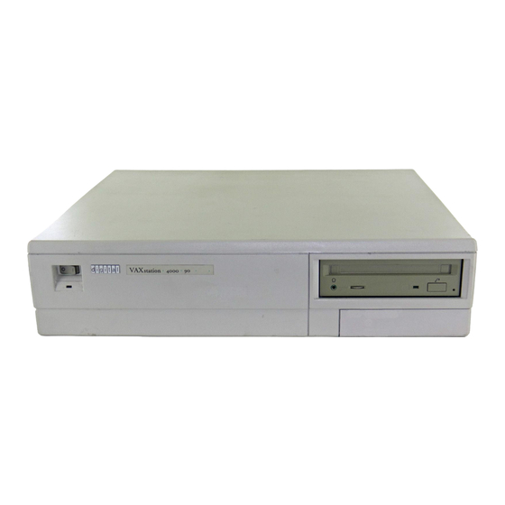
System Components • Available Options System Capabilities The VAXstation 4000 workstation offers all the advantages of an Overview of integrated computing environment based on Digital Equipment Features Corporation’s VAX architecture. The Model 90 system offers the following features: • Desktop computing •... - Page 14 System Capabilities • A variety of options for increasing storage capacity, as well as adding communications, memory, enhanced graphics, and other capabilities to your system • Standard Ethernet and ThinWire Ethernet ports for connection to a DECnet network • A password security feature for additional system security The VAXstation Figure 1–1 shows a fully configured system.
-
Page 15: Components Shipped
System Components System Components Listed below are the basic components of your system. Components Shipped Figure 1–2 shows each component. System unit Monitor Keyboard Universal strain relief strap System power cord Monitor power cord Loopback connector Monitor video cable One T-connector and two terminators Network label Mouse with mousepad Documentation... -
Page 16: System Components
System Components Figure 1–2 shows all the basic components of your system. System Components Figure 1–2 System Components MLO-008074 1–4 Your VAXstation 4000 Model 90 System... -
Page 17: Front Of System Unit
System Components Front of Figure 1–3 shows the ports, switches, and indicators on the front System Unit of the system unit. Table 1–1 explains the function of each. Figure 1–3 Front of System Unit MLO-008072 Your VAXstation 4000 Model 90 System 1–5... -
Page 18: Front Of System Unit
System Components Front Table 1–1 describes the ports, switches, and indicators on the Components front of the system unit. Table 1–1 Components: Front of System Unit Number Feature Function On/Off switch Power switch for system unit (shown in Figure 1–3 in off (O) position). -
Page 19: Back Of System Unit
System Components Figure 1–4 shows the ports, switches, and indicators on the back Back of System Unit of the system unit. Table 1–2 explains the function of each. Figure 1–4 Back of System Unit MLO-008073 Your VAXstation 4000 Model 90 System 1–7... -
Page 20: Back Of System Unit
System Components Table 1–2 describes the ports, switches, and indicators on the Component Descriptions back of the system unit. Table 1–2 Components: Back of System Unit Number Feature Function SCSI port Used to connect Small Computer System Interface (SCSI) peripheral devices to the system unit. -
Page 21: Available Options
System Components Table 1–2 (Cont.) Components: Back of System Unit Number Feature Function Standard Ethernet Used to connect to a standard port Ethernet network. Network switch Used to select ThinWire Ethernet or standard Ethernet networking options. Move the switch to the left for standard Ethernet or right for ThinWire Ethernet. -
Page 22: Vaxstation 4000 Devices And Options
Available Options An ‘‘X’’ in Table 1–3 indicates that the option can be installed in either the system unit or an expansion box. Table 1–3 VAXstation 4000 Devices and Options System Expansion Option Unit RZ23L, RZ24, RZ24L, RZ25 fixed disk drives RZ56, RZ57, RZ58 fixed disk drives RX26 diskette drive RRD42 compact disc drive... - Page 23 Available Options External options for the VAXstation 4000 Model 90 include: • Button box (programmable function keyboard) • Dial box • Floor stand • Headset • Multiple-box rack • Printer • Remote cable option • Tablet Ordering Contact your Digital sales representative for more information about ordering any of these options.
-
Page 25: Introduction
Installing Your VAXstation 4000 Introduction This chapter explains how to install the standalone system, run system start-up tests, and record information about your system. This chapter covers the following topics: Chapter Topics • Installing Your System • Putting Your System in Console Mode •... -
Page 26: Assembling The T-Connector
Installing Your System Installing Your System Installation Table 2–1 lists the steps you take to install your VAXstation Overview 4000 Model 90 system. The remaining pages in this section explain and illustrate these steps in detail. Table 2–1 Installation Steps for Your VAXstation 4000 Model 90 System Connect the loopback and T-connector to the system unit. -
Page 27: Attaching The Loopback And T-Connector
Installing Your System Attach the Follow Figure 2–2 to attach the loopback connector Loopback and the T-connector . Turn the T-connector to the right after you T-connector connect it to the system unit. Figure 2–2 Attaching the Loopback and T-connector MLO-008077 Installing Your VAXstation 4000 2–3... -
Page 28: Connecting The Mouse And Keyboard
Installing Your System Connect the Follow Figure 2–3 to connect the mouse cable and the Mouse and keyboard cable to the system unit. Keyboard Figure 2–3 Connecting the Mouse and Keyboard MLO-008075 2–4 Installing Your VAXstation 4000... -
Page 29: Attaching The Monitor Cable
Installing Your System Attach the Follow Figure 2–4 to attach the monitor video cable and the Monitor Cables monitor power cord to the system unit. Make sure you align the connectors in the monitor video cable; the alignment for the LCSPX connector is opposite of the alignment for the SPXg and SPXgt connectors. -
Page 30: Attaching The Universal Strain Relief Strap
Installing Your System Follow Figure 2–5 to attach the notched end of the universal Universal Strain Relief Strap strain relief strap to the green (G) BNC connector on the monitor video cable, and the other end under the cable junction block . -
Page 31: Video In/Video Out Connectors
Installing Your System Attach the Follow Figure 2–6 to attach the BNC connectors of the monitor Monitor Video video cable to the back of the monitor. Cable Monochrome monitor: Section of Figure 2–6 shows the back of a monochrome monitor. Attach only the middle cable. Color monitor: Section of Figure 2–6 shows the back of a color monitor. -
Page 32: Attaching The Monitor Power Cord
Installing Your System Attach the Follow Figure 2–7 to attach the monitor power cord to the Monitor Power back of the monitor. Cord Figure 2–7 Attaching the Monitor Power Cord MLO-008081 2–8 Installing Your VAXstation 4000... -
Page 33: Factory Installed Software Sticker
Installing Your System Factory A yellow sticker covering the power connection on the back Installed of your system unit indicates that you have OpenVMS factory Software installed software. (If you do not have a sticker, the configuration Sticker you ordered did not support factory installed software.) Remove the sticker shown in Figure 2–8 before you go to the next step. -
Page 34: Connect The System Power Cord
Installing Your System Follow Figure 2–9 to attach the system power cord to the back Connect the System Power of the system unit. Plug the other end of the system power cord into a power outlet. Cord Figure 2–9 Attaching the System Power Cord MLO-008082 This completes the system installation. -
Page 35: Turn On ( | ) Your System
Installing Your System Monitor: Turn on your monitor first. See your monitor guide for Turn On ( | ) Your System details about monitor features. System Unit: Press the On/Off switch to the on ( | ) position, as shown in Figure 2–10. Figure 2–10 On/Off Switch MLO-008083 You should hear a series of beeps, and see the diagnostic lights... -
Page 36: Successful Start-Up Display
Installing Your System Successful As each system test completes, the status bar fills. The more Start-Up memory you have, the longer the start-up tests take. When all Display tests complete, without errors, the status bar fills completely, and the console prompt (>>>) displays, as shown in Figure 2–11. -
Page 37: Putting Your System In Console Mode
Putting Your System in Console Mode Putting Your System in Console Mode In console mode, your system is controlled by the console Console Mode subsystem, rather than the operating system. Your system enters console mode before the operating system has been started, or whenever the operating system is interrupted, for example, when the halt button is pressed. -
Page 38: Recording Information About Your System
Recording Information About Your System Recording Information About Your System Why Record It is helpful to record specific system information in case you Information? need to provide information to your system manager or your Digital service representative. Where to Find Table 2–2 shows examples of the system information you should Information record for future reference. - Page 39 Recording Information About Your System Table 2–2 (Cont.) Your System Information How to find the Information Example information Error line ??001 9 NI 0172 Enter the SHOW CONFIG command and press the Return key at the console prompt ( >>> ). SCSI ID 0 RZ24 Enter the SHOW...
-
Page 40: Attaching The Network Label
Recording Information About Your System Attaching the Record your Ethernet hardware address and your system node Network Label name on the network label. Open the door on the front of your system and attach the network label, as shown in Figure 2–13. Figure 2–13 Attaching the Network Label MLO-008086 2–16 Installing Your VAXstation 4000... -
Page 41: Connecting Your System To The Network
Connecting Your System to the Network Introduction This chapter explains how to connect your system to a ThinWire Ethernet network and to a standard Ethernet network. After installing your system, you are ready to connect to the Chapter Topics network. This chapter covers the following network connection tasks: •... -
Page 42: Verifying The Ethernet Subsystem
Verifying the Ethernet Subsystem Verifying the Ethernet Subsystem Before connecting to a network, you need to verify that the Steps to Verify Ethernet subsystem (the Ethernet controller chip on the system board) is operating properly by following these steps: 1. Turn on ( | ) your system. The light on the back of the Ethernet loopback connector should come on. -
Page 43: Connecting To The Network
Verifying the Ethernet Subsystem 2. Enter the following command at the console prompt: >>> TEST NI Return When the status bar fills and the message OK displays on the screen, the system’s Ethernet subsystem is working and verification is complete. If the screen displays a pair of question marks (??), there is an error. -
Page 44: Network Switch
Connecting to the Network Figure 3–2 Network Switch MLO-008088 5. Connect the standard Ethernet cable to the standard Ethernet port on the back of the system unit, as shown in Figure 3–3. 3–4 Connecting Your System to the Network... -
Page 45: Connecting To Thinwire Ethernet
Connecting to the Network Figure 3–3 Ethernet Cable in Ethernet Port MLO-008091 6. Move the sliding lock on the port to the left to secure the connection. 7. Connect the other end of the Ethernet cable to the network outlet. Follow these steps to connect your system to the ThinWire Connecting Ethernet network:... -
Page 46: Adding Thinwire Cable
Connecting to the Network 4. Add the ThinWire cable to the T-connector in place of the terminators, as shown in Figure 3–4. Figure 3–4 Adding ThinWire Cable MLO-008089 5. Reconnect the T-connector to the ThinWire Ethernet port on the back of the system unit, as shown in Figure 3–5. Figure 3–5 Reconnecting ThinWire Cable MLO-008090 3–6 Connecting Your System to the Network... -
Page 47: Connecting To The Decconnect Faceplate
Connecting to the Network 6. Attach one end of the ThinWire Ethernet cable to the DECconnect faceplate, on the wall, as shown in Figure 3–6. Figure 3–6 Connecting to the DECconnect Faceplate MLO-008092 7. Check that the T-connector at the other end of the ThinWire cable is firmly attached to the ThinWire port on the back of your system unit. -
Page 48: Verifying The Ethernet Connection
Verifying the Ethernet Connection Verifying the Ethernet Connection Verify Follow these steps to verify your Ethernet connection: Command 1. Turn on ( | ) your system. 2. Enter the following command at the console prompt: >>> TEST NI Return When the status bar fills and the message OK displays on the screen, the system’s Ethernet subsystem is working and verification is complete. -
Page 49: Removing A System From Thinwire Ethernet
Removing a System from ThinWire Ethernet Removing a System from ThinWire Ethernet Before halting or turning off your system, see the operating Caution: Follow system documentation for shutdown procedures. If your system Shutdown is part of a networked work group, do not turn off, halt, or restart the system without notifying work group members. -
Page 51: Using Your System
Using Your System Introduction After you install your system, you are ready to use your system. This chapter explains how to turn your system off and on, display the system configuration, use commands in console mode, and set the password security feature. Chapter Topics This chapter covers the following tasks: •... -
Page 52: Turning Your Workstation On And Off
Turning Your Workstation On and Off Turning Your Workstation On and Off Turn on ( | ) the monitor with the monitor On/Off switch. The Turning On the Monitor monitor power does not turn on when the system unit is turned Turn on your other equipment in the following order: Turning On Your System... -
Page 53: Starting Your System
Starting Your System Starting Your System Enter the Boot If your workstation has an internal disk drive, and has the boot Command device set, you can run the OpenVMS factory installed software by entering the following command at the console prompt (>>>): >>>... -
Page 54: Show Config Display
Reviewing Your System Configuration Figure 4–1 SHOW CONFIG Display >>> SHOW CONFIG KA49-A Vn.n 08-00-2B-0A-7D-CB 32MB DEVNBR DEVNAM INFO ------ ------ -------------------------------- LCSPX Highres 8 Plane 4Mpixel FB-Vn.n CACHE 32MB 0A,0B,0C,0D=16MB, 1E,1F,1G,1H=16MB SCSI 0-RZ24 0-RZ24 5-RZ25 5-RZ25 6-INITR 6-INITR COMM PRS V1.0 >>>... -
Page 55: Graphics Board Mnemonics
Reviewing Your System Configuration Table 4–1 Graphics Board Mnemonics Mnemonic Meaning LCSPX High resolution, color,8-plane SP3D High resolution, color, 8- or 24-plane, 3-D The memory line displays the total number of megabytes of memory installed in the eight memory slots. It also lists the type of memory board in each 4-board set. -
Page 56: Show Config Display With Error
Reviewing Your System Configuration Error Messages Problems with a particular device are indicated by a pair of question marks (??) in the column next to the mnemonic of the device or system component, as shown in Figure 4–2. Figure 4–2 SHOW CONFIG Display with Error >>>... -
Page 57: Using Console Commands
Using Console Commands Using Console Commands The commands that you enter at the console prompt (>>>) let you display information about your system, as well as set and test certain components. Using HELP To see a list of the console commands, enter HELP at the console prompt (>>>) and press the Return key. -
Page 58: Test Commands
Using Console Commands Table 4–3 lists the function of each SET command. Commands Table 4–3 SET Commands To set this feature: Enter this command: Set boot flags SET BFLG Define the boot device SET BOOT Set the recovery action SET HALT Select the keyboard language SET KBD Enable the password bit... -
Page 59: Using The Password Security Feature
Using the Password Security Feature Using the Password Security Feature Restricted In normal operation, console mode ( >>> ) allows all console Access operator privileges, such as HALT, SET, DEPOSIT, and EXAMINE. Some companies require that direct access to memory and kernel system operation be restricted to authorized personnel only. -
Page 60: Nonprivileged Console Commands
Using the Password Security Feature Nonprivileged The console commands listed in Table 4–5 are accessible without Console access to privileged mode. Commands Table 4–5 Nonprivileged Console Commands LOGIN Allows password entry to the privileged state. BOOT Allows you to boot from the default boot (no parameters) device. -
Page 61: Enabling The Password Security Feature
Using the Password Security Feature Enabling After you enter and confirm the password, you must enable the the Security password security feature as described in Table 4–7. Feature Table 4–7 Enabling the Password Security Feature Step You enter: System displays: SET PSE 1 >>>... -
Page 62: Moving Your System
Moving Your System Moving Your System See the operating system documentation for shutdown Shutting Down procedures. If your system is part of a networked work group, do not turn off, halt, or restart the system without notifying work group members. Take the following steps to repack the system to move it to another location: 1. -
Page 63: Start-Up Display
Testing System Components Introduction A variety of tests can be run on your system to verify that the components are working properly and to identify the source of any problems. This chapter explains how to perform and interpret the results of system tests and how to reboot your system after testing. -
Page 64: Start-Up Display With Error Message
Interpreting System Start-Up Displays If there is a problem, the start-up test display shows an error Start-Up Display with message. Figure 5–1 shows the elements in a start-up display containing an error message. Error Message Figure 5–1 Start-Up Display with Error Message KA49-A Vn.n 08-00-2B-04-03-12 32MB... -
Page 65: Id Numbers And Definitions
Interpreting System Start-Up Displays Use the following tables to understand each piece of an error message. See Table 5–1 to identify the ID number of the part that your The ID Digital service representative needs to replace. Number Table 5–1 ID Numbers and Definitions ID Number Definition System board... -
Page 66: Component Numbers And Mnemonics
Interpreting System Start-Up Displays The error message contains a component number The Faulty component mnemonic , which identify the faulty device or Component component in your system. Table 5–2 explains what the numbers and mnemonics mean. Table 5–2 Component Numbers and Mnemonics Component Component Number... -
Page 67: Error Messages
Interpreting System Start-Up Displays Table 5–3 explains some common error message numbers you The Error Message may see when you turn on your system or run a test. If you see other messages that you do not understand, call your Digital Number service representative. -
Page 68: Diagnostic Lights
Interpreting Diagnostic Lights Interpreting Diagnostic Lights Where the The diagnostic lights on the front of the system unit indicate Lights Are the status of the system as it is powering up. After the power is turned on but before any commands are entered, the lights are all on. -
Page 69: Diagnostic Light Patterns Of Common Problems
Interpreting Diagnostic Lights What the Lights Diagnostic lights that remain on after system tests are complete Mean indicate an error. Table 5–4 lists some common errors indicated by the diagnostic light patterns. In these patterns, X=on and O=off. Table 5–4 Diagnostic Light Patterns of Common Problems Pattern 7654 3210... -
Page 70: Testing System Components
Testing System Components Testing System Components To test a particular device or component in your system, follow Testing a Single Component these steps: 1. Use Table 5–2 to find the number or mnemonic for the device or component you want to test. 2. -
Page 71: Testing Several Components
Testing System Components If you want to test a consecutive series of devices or components, Testing Several Components enter TEST followed by the first and last numbers or mnemonics of the series separated by a colon, and press the Return key. Example For example, to test the first five components listed in Table 5–2, enter:... - Page 72 Testing System Components Using the To use the system exerciser, follow these steps: System 1. To test a drive, insert media in the SCSI devices on your Exerciser system that support removable media. For example: • If your system has an RRD42 compact disc drive, insert a disc.
-
Page 73: Interrupting The System Exerciser
Testing System Components Interrupting If you interrupt the system exerciser with a , the sytem CTRL/C the System displays a question that asks if you want to review the tests Exerciser that were run until the interrupt (1= yes), or exit the test (0= no review). -
Page 74: Successful Test
Testing System Components Figure 5–3 shows a successful system exerciser test. As testing Successful Test progresses, each status bar fills. Figure 5–3 Successful System Exerciser Test MLO-008097 Elapsed time User environment Firmware version number Component number Component mnemonic Status bar 5–12 Testing System Components... -
Page 75: Unsuccessful Test
Testing System Components Unsuccessful Figure 5–4 shows a system exerciser display with an error line Test for component number 10, the SCSI controller. Figure 5–4 System Exerciser Display with an Error Line SCSI 0098 0 00:01:06 MLO-008098 Error line Component number Error indicator Component mnemonic ID of failed device... -
Page 76: Requesting A Test Summary
Testing System Components Requesting a When the test finishes, the system exerciser displays the Test Summary following question, asking if you want to see a summary display of the system test: SYT_DISPLY_SMRY (’1’ = Y) If you answer 1 (yes), the system displays a test summary. The summary, shown in Figure 5–5, always begins with the graphics device. -
Page 77: Requesting No Test Summary Display
Testing System Components Requesting No If you answer 0 (no), a display similar to the following is shown Test Summary after a few minutes: Display ?06 HLT INST PC=00003C17 PSL=00000000 >>> This display tells you that the test has halted and the system has returned you to the console prompt ( >>>... -
Page 78: Device Mnemonic
Resuming Normal Operation After Testing Device Mnemonic Table 5–5 OpenVMS Device Mnemonic OpenVMS Device Device and Location Mnemonic Fixed disk in system unit or DKAx00 expansion box (SCSI ID 0–7) Mass storage on remote system EZA0: Tape (SCSI ID 0–7) MKAx00 x = the SCSI ID for a particular device. -
Page 79: Handling Problems
Handling Problems Introduction If you should encounter a problem with your system, use the information in this chapter to diagnose and solve the problem. This chapter explains the following procedures: Chapter Topics • Checking Cable Connections • Troubleshooting System Components •... -
Page 80: Checking Cable Connections
Checking Cable Connections Checking Cable Connections To check all the cable connections, follow these steps: Shut Down the System 1. Refer to your operating system documentation for shutdown procedures before turning off your system and peripheral devices. Failure to meet this requirement can cause loss of user data or system failure. -
Page 81: Turn System Back On
Checking Cable Connections Turn the equipment back on ( | ) in the following order: Turn System Back On • Monitor • Peripheral devices (printers, modems) • Storage expansion box • System unit Adjust the brightness and contrast on your monitor. If you still have a problem, refer to the following troubleshooting tables. -
Page 82: System Unit
Troubleshooting System Components Table 6–1 provides information for solving system unit System Unit problems. Table 6–1 Problems with the System Unit Symptom Possible Cause Suggested Solution System unit fan is off. Power cord is not Check the power cord connections at both connected. -
Page 83: Monitor
Troubleshooting System Components Monitor Table 6–2 lists suggestions for solving monitor problems. Table 6–2 Problems with the Monitor Symptom Possible Cause Suggested Solution Start-up display does not Monitor is not turned on. Check the monitor On/Off switch; be sure appear after 2 minutes. it is on ( | ). -
Page 84: Mouse/Tablet
Troubleshooting System Components Mouse/Tablet Table 6–3 lists suggestions for solving problems with your mouse or tablet. Table 6–3 Problems with the Mouse or Tablet Symptom Possible Cause Suggested Solution Mouse or optional CTRL F3 was pressed Press CTRL F3 again to restart the tablet pointer does by mistake, and system pointer mode. -
Page 85: Network
Troubleshooting System Components Network Table 6–5 lists suggestions for solving network problems. Table 6–5 Problems with the Network Symptom Possible Cause Suggested Solution NI error message is Network switch is not Check that the network switch is in displayed when testing set properly. -
Page 86: Reporting Problems To Your Digital Service Representative
Reporting Problems to Your Digital Service Representative Reporting Problems to Your Digital Service Representative If you followed the corrective actions described in this chapter yet Before You Call continue to have problems with your system, take the following steps before you call your Digital service representative: 1. -
Page 87: A Alternate Start-Up Procedures
Alternate Start-Up Procedures Introduction This appendix explains how to set alternate start-up procedures, including how to reboot your system and change the default recovery action. It also explains how to change your keyboard language setting. Appendix This appendix covers the following procedures: Topics •... -
Page 88: Changing The Keyboard Language
Changing the Keyboard Language Changing the Keyboard Language Before halting or turning off your system, see the operating Turning Off Your System system documentation for shutdown procedures. If your system is part of a networked group, do not turn off, halt, or restart the system without notifying work group members. -
Page 89: Setting The Default Boot Device
Setting the Default Boot Device Setting the Default Boot Device The Default When your system arrives from the factory, it is set to boot from Boot Device a particular disk drive, which is the default boot device. You can change the default boot device to any of the devices listed in Table A–1, but the operating system software must reside on that device. -
Page 90: Example
Setting the Default Boot Device Example For example, to set the boot device to be the fixed disk at SCSI ID 3 in the system unit, enter: >>> SET BOOT DKA300 Return If you are powering your system off and on frequently, you Short-Cut may want to shorten the time required for the boot process. - Page 91 Changing the Default Recovery Action Before halting or turning off your system, see the operating Changing Default system documentation for shutdown procedures. If your system is part of a networked group, do not turn off, halt, or restart the Recovery system without notifying work group members.
-
Page 92: Setting The Default Boot Flags
Setting the Default Boot Flags Setting the Default Boot Flags The SET BFLG (boot flag) command lets you define parameters Who Should Set the Boot that the system will use each time it boots. This command Flag should be used only by developers and other technical users who need and understand its capabilities. - Page 93 Using the Alternate Console Feature To connect a terminal, follow these steps: Connecting a Terminal as 1. Halt the system by pressing the halt button behind the front an Alternate door of the system unit. Console 2. Turn off (O) the system unit. 3.
-
Page 95: Cables
DSW21 Synchronous Communications Adapter Installation Information for the United Kingdom Appendix This appendix includes installation information required for the Topics United Kingdom only. It covers the following topics: • Cables • Equipment Between the DSW21 Adapter and a Digital Circuit •... -
Page 96: Safety Warning Conditions
Cables The port indicated by the label "SAFETY WARNING: See Safety Warning Conditions Instructions for Use" does not provide sufficient isolation to satisfy the requirements of the relevant parts of standard BS6301. Any product connected to this port must meet one of the following conditions: •... -
Page 97: Module Power
Host Power Rating Module Power Since the host and the approved equipment are proprietary to Digital Equipment Corporation, Digital controls the power source and sink ratings. All available host enclosures have the power capacity to supply all module permutations. Digital has designed all permutations of the host configuration to operate within the limits of the host power rating, as shown in Table B–1. -
Page 98: Babt Approved Service Specifications For The Dsw21 Synchronous Communications Adapter For Uk Compliance
Approved Service Specifications Approved Service Specifications Table B–2 lists the British Approvals Board for UK Compliance Telecommunications (BABT) service specifications for UK compliance. Note the following relative to this table: • The total length of cable must not exceed 27 feet (823 cm). •... -
Page 99: Babt Host-Independent Approvals
BABT Host-Independent Approvals BABT Host-Independent Approvals Approval When the DSW21 Synchronous Communications Adapter is Criteria approved by BABT, it can be installed only in an approved host with approved attachments. For approval, the host and attachments must be either of the following: •... -
Page 100: Clearance And Creepage Distances
BABT Host-Independent Approvals Table B–3 lists the clearance and creepage distances that Clearance must be maintained between the DSW21 Synchronous Communications Adapter and other parts of the host, including other expansion cards. Also listed are creepage distances, which apply when you install the DSW21 in a controlled environment. -
Page 101: Creepage Distance
BABT Host-Independent Approvals You can check creepage distances by measuring the distance Checking Creepage between adjacent parts, as shown in Figure B–1, where: Distances Indicates the clearance distance, that is, the shortest distance in air between two points. Indicates the creepage path between the same two points, that is, the continuous path along the surface. - Page 103 Model 90 System Specifications Appendix This appendix lists the following VAXstation 4000 Model 90 Topics system hardware specifications: • Dimensions • Electrical • Storage • Operating conditions • Nonoperating conditions Model 90 System Specifications C–1...
-
Page 104: System Unit Dimensions (Diskless System
System Specifications System Specifications Dimensions Table C–1 lists the dimensions of the VAXstation 4000 system unit. Table C–1 System Unit Dimensions (Diskless System) Weight Height Width Depth 4½ kg 10.9 cm 48.2 cm 40 cm (10 lb) (4.3 in) (19.0 in) (15½... -
Page 105: System Component Specifications
System Specifications Table C–3 lists the specifications of the VAXstation 4000 system General Specifications components. Table C–3 System Component Specifications Component Description Processor KA49 CPU DRAM 16-MB minimum, 128-MB maximum (no on-board memory) ROM memory 512 KB flash programmable Optional fixed disks One or two 209-MB, or 426-MB integral 3½-inch fixed disks Optional RX26 diskette drive... -
Page 106: Storage Specifications
System Specifications Table C–4 lists the environmental specifications for the Storage Specifications VAXstation 4000 system. Table C–4 System Storage Specifications Temperature range 5°C to 50°C (41°F to 122°F) Relative humidity 10% to 95% (noncondensing) Altitude 0 to 2400 m (0 to 8000 ft) Maximum wet bulb temperature 32°C (90°F) Minimum dew point... - Page 107 Index Commands (cont’d) privileged, 4–9 SET, 4–8 Alternate console SHOW, 4–7 setting the baud rate, A–7 TEST, 4–8 switch location, 1–6 Communications/printer port using, A–6 function of, 1–8 Alternate start-up procedures Components setting, A–1 to A–6 identifying faulty, 5–1 Audio speaker switch shipped (fig.), 1–4 function of, 1–6 Configuration...
- Page 108 Diagnostics Headset jack commands, 4–8 function of, 1–6 self tests, 5–12 HELP command, 4–7 start-up, 5–1 system exerciser, 5–9 tests, 5–8 ID numbers Digital service representative, 6–8 of system components, 5–3 DKAx00 device, 5–15, A–3 Keyboard Error messages changing language, A–2 in the system exerciser display, 5–13 connecting (fig.), 2–4 start-up display, 5–7...
- Page 109 Monitor video port Power-up function of, 1–8 See Start-up Mouse Privileged console commands, 4–9 connecting (fig.), 2–4 Problem solving Mouse port system exerciser, 5–9 function of, 1–8 Problems identifying, 5–7 reporting, 6–8 troubleshooting table, 6–3 Network connecting to, 3–2 label, attaching (fig.), 2–16 troubleshooting, 6–7 Reboot recovery action, A–4 Network switch...
- Page 110 Specifications, C–1 electrical, C–2 environmental, C–4 T-connector system, C–3 assembling (fig.), 2–2 Standard Ethernet attaching (fig.), 2–3 connecting (fig.), 3–5 removing (fig.), 3–9 port function, 1–9 Tape drives Start-up boot device name, 5–15, A–3 error messages, 5–7 TEST 100 command, 5–10 screen display (fig.), 3–2 TEST command, 4–8 successful test display, 5–9...
-
Page 111: Technical Support
Fax: (809) 749-8377 3 Digital Plaza, 1st Street Suite 200 Metro Office Park San Juan, Puerto Rico 00920 Canada Phone: 800-267-6215 Digital Equipment of Canada Ltd. Fax: (613) 592-1946 100 Herzberg Road Kanata, Ontario, Canada K2K 2A6 Attn: DECdirect Sales International —————... - Page 113 Reader’s Comments VAXstation 4000 Model 90 Series Owner’s and System Installation Guide EK–VAXOG–IN. B01 Your comments and suggestions help us improve the quality of our publications. Thank you for your assistance. I rate this manual’s: Excellent Good Fair Poor Accuracy (product works as manual says) Completeness (enough information) Clarity (easy to understand) Organization (structure of subject matter)
- Page 114 United States BUSINESS REPLY MAIL FIRST CLASS PERMIT NO. 33 MAYNARD MASS. POSTAGE WILL BE PAID BY ADDRESSEE DIGITAL EQUIPMENT CORPORATION Information Design and Consulting PKO3–1/D30 129 PARKER STREET MAYNARD, MA 01754-2198 Do Not Tear – Fold Here...
Need help?
Do you have a question about the VAXstation 4000/90 Series and is the answer not in the manual?
Questions and answers