Table of Contents
Advertisement
Quick Links
AlphaStation 600 Series
User Information
Part Number: EK-AS800-UI. B01
June 1995
This book introduces the AlphaStation 600 Series system. Use the information in this
book to configure, start, use, update, and troubleshoot your system. You will also find
general system information, such as console commands and system care, in this book.
Revision/Update Information:
First Revision.
Digital Equipment Corporation
Maynard, Massachusetts
Advertisement
Table of Contents
Troubleshooting

Related Manuals for Digital Equipment AlphaStation 600 Series


Summary of Contents for Digital Equipment AlphaStation 600 Series
- Page 1 Part Number: EK-AS800-UI. B01 June 1995 This book introduces the AlphaStation 600 Series system. Use the information in this book to configure, start, use, update, and troubleshoot your system. You will also find general system information, such as console commands and system care, in this book.
- Page 2 June 1995 Digital Equipment Corporation makes no representations that the use of its products in the manner described in this publication will not infringe on existing or future patent rights, nor do the descriptions contained in this publication imply the granting of licenses to make, use, or sell equipment or software in accordance with the description.
- Page 3 Information - Class B This device complies with Part 15 of the FCC rules. Operation is subject to the following conditions: (1) this device may not cause harmful interference, and (2) this device must accept any interference received, including interference that may cause undesired operation.
-
Page 5: Table Of Contents
Security Lock ....................1-15 Passwords..................... 1-15 2 System Overview ................2-1 Introduction......................2-1 System Unit ......................2-1 PCI Architecture ....................2-2 AlphaStation 600 Series I/O Subsystem..............2-2 The Keyboard ....................... 2-2 System Front Panel ....................2-4 System Rear Panel ....................2-6... - Page 6 Table of Contents 3 Installing System Options ............3-1 Introduction ......................3-1 System Unit Components..................3-2 Left Side Panel...................... 3-3 Removing the Left Side Panel ................ 3-3 Replacing the Left Side Panel ................ 3-5 System Board......................3-6 System Memory....................3-8 Cache Memory....................
- Page 7 Table of Contents Set Default Environment Variables............A-2 Set Default Configuration............... A-2 Manage Boot Selection Menu..............A-2 Machine Specific Setup ................A-3 Boot (Boot Selection Identifier).............. A-3 Boot an Alternate Operating System............A-3 Other Commands of Interest................A-3 Setup Autoboot..................A-3 Install New Firmware ................
- Page 8 Table of Contents C Technical Specifications............C-1 Introduction ......................C-1 System Specifications ...................C-1 External System Connectors..................C-3 Parallel Port Connector ..................C-4 Serial Port Connectors..................C-5 Keyboard and Mouse Connectors ..............C-5 SCSI Connectors ....................C-6 Expansion Slots....................C-8 Power Supply and Input Power Requirements ............C-9 System Board Jumper Locations ................. C-10 I/O Subsystem Module..................
- Page 9 Table of Contents List of Figures Figure 1-1. AlphaStation 600 Series System............1-2 Figure 1-2. Recommendations for Posture and Work Habits........1-4 Figure 1-3. System Airflow (Side View, Cover Removed) ........1-8 Figure 1-4. Connecting Cables and the Power Cord..........1-10 Figure 1-5.
- Page 10 Table of Contents List of Tables Table 1-1. Recommendations for Posture and Work Habits........1-4 Table 1-2. System Shutdown Commands .............1-14 Table 2-1. Key Groups and Functions ..............2-3 Table 2-2. Front Controls, Indicators, and Drive Bay Locations ......2-4 Table 2-3.
- Page 11 Table of Contents Table G-4. Installed Software................G–3 Table G-5. Additional Component Information ............G–3...
- Page 13 AlphaStation 600 Series system. You can also find general system information such as console commands and system care in this book. Audience If you will be operating, configuring, or adding options to the AlphaStation 600 Series system, the information included in this book will be helpful to you. Organization of the Information This information for users covers the following topics: •...
- Page 14 Preface • Appendix B, System Care, describes how to clean your system, monitor, mouse, and keyboard. It also contains instructions for moving and reinstalling your system. • Appendix C, Technical Specifications, describes the technical characteristics of the system. • Appendix D, Device Mapping, lists system device address mapping information, including I/O addresses and interrupts.
- Page 15 Preface Abbreviations This guide uses the following abbreviations: Abbreviation Meaning alternating current ampere advanced RISC computing (Windows NT console) ARCINST ARC installation program Celsius compact disc CD-ROM compact disc read-only memory International Commission for Conformity Certification of Electrical Equipment configuration file centimeters central processing unit Canadian Standards Association...
- Page 16 Preface Abbreviation Meaning kilobit kilobyte kilogram pound light-emitting diode meter media adapter unit megabit megabyte megahertz. millimeter nanoseconds NVRAM nonvolatile random-access memory DEC Open Software Foundation/1 UNIX operating system peripheral component interconnect RISC reduced instruction set computing read-only memory SCSI small computer system interface SIMM single in-line memory modules...
- Page 17 You may wish to consult the following information resource for additional information about your AlphaStation 600 Series system: • AlphaStation 600 Series Installation Information (order number EK-AS800-IN), which presents a graphical overview of the AlphaStation 600 Series system installation. Contact your distributor or Digital representative for other available product-related information. xvii...
-
Page 19: Getting Started
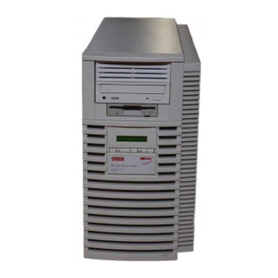
This chapter describes how to install, start, restart, and turn off your AlphaStation 600 Series system. You can also find information here about preloaded software as well as guidelines for system security. Figure 1-1 shows a typical AlphaStation 600 Series system. -
Page 20: Before Starting Your System
Getting Started Figure 1-1. AlphaStation 600 Series System Before Starting Your System Before you start your system, follow this procedure: 1. Read and understand the information supplied with your system. 2. Select a well-ventilated site near a grounded power outlet and away from sources of excessive heat. -
Page 21: Posture And Work Habits
Getting Started _________________________ NOTES____________________________ • Do not install optional hardware or application software until you have started your system and verified that the base system is working correctly. • • On systems that have preloaded software, a label attached to the system unit informs you that there is licensed software installed. -
Page 22: Figure 1-2. Recommendations For Posture And Work Habits
Getting Started Figure 1-2. Recommendations for Posture and Work Habits Table 1-1. Recommendations for Posture and Work Habits Adjust Figure To allow the following conditions: Callout Chair Your feet are flat on the floor. Your legs are vertical and form a right angle to the floor. Your thighs are horizontal, and they are not bearing weight. - Page 23 Getting Started Table 1-1. Recommendations for Posture and Work Habits (continued) Adjust Figure To allow for the following conditions: Callout Keyboard and Your wrists are straight and do not flex more than 15 degrees. Mouse They are supported and do not rest on sharp edges. If you use a mouse, rest your hand on the mouse so your wrist is not on the work surface.
-
Page 24: Identifying The Correct Ac Power Cord
• The cords are UL-listed and CSA-certified, rated for use at 250V AC with a current rating that is at least 125% of the current rating of the AlphaStation 600 Series system. In Europe, the cordage carries the <HAR> mark. -
Page 25: Installing Your System
Getting Started Installing Your System The AlphaStation 600 Series Installation Information you received with your system graphically outlines the steps to follow to install your system. 1. Make sure you received all of your system components. Use Appendix G, Equipment Log, to list your equipment. -
Page 26: Figure 1-3. System Airflow (Side View, Cover Removed)
Getting Started Rear of system unit Front of system unit Figure 1-3. System Airflow (Side View, Cover Removed) -
Page 27: Connecting System Components
Getting Started Connecting System Components To connect the components of your AlphaStation 600 Series system, follow this procedure: __________________________ NOTE ____________________________ The AlphaStation 600 Series system runs on 88V–268V AC and 48–62 Hz. The system uses an autosensing power supply. -
Page 28: Figure 1-4. Connecting Cables And The Power Cord
Getting Started Mouse connector Keyboard connector SCSI bus connector - 50-pin (narrow) SCSI bus connector - 68-pin (wide) Network connectors Parallel port Serial ports Figure 1-4. Connecting Cables and the Power Cord 1-10... -
Page 29: Network Connection
See the section on SCSI Termination in Chapter 3 for additional information. Network Connection The AlphaStation 600 Series I/O subsystem module has thick-wire, ThinWire, and twisted- pair connectors for connecting to a network. Use the appropriate connector for your application. -
Page 30: Preloaded Operating System Software
Getting Started Figure 1-5. Starting Your System Preloaded Operating System Software Your AlphaStation 600 Series system comes with one of the following operating systems preloaded: • DEC OSF/1 • OpenVMS __________________________NOTE ____________________________ Windows NT is available but is not preloaded on your AlphaStation 600 Series system. -
Page 31: Dec Osf/1
Getting Started DEC OSF/1 If you are using the DEC OSF/1 operating system, either you see a >>> prompt (if auto_action is set to Halt) or the system proceeds to boot DEC OSF/1 (if auto_action is set to Boot) when you power on your system. For more information, refer to your operating system documentation. -
Page 32: Turning Off Your System
Getting Started Turning Off Your System Before turning off your system, make sure to save and close all open files. If you turn the system off without saving and closing files, you could corrupt some or all of your data. To turn off your system, follow this procedure: 1. -
Page 33: Computer Security
Use the security lock and passwords to protect your AlphaStation 600 Series system. Security Lock To avoid theft of internal components, your AlphaStation 600 Series system comes with a security key lock, which is located on the back of your system unit. When this lock is in the locked position, no one else can open the system box. -
Page 35: System Overview
(PCI) architecture, the keyboard, the system unit front panel, and the system unit rear panel. System Unit Your AlphaStation 600 Series system uses a high-performance Alpha architecture CPU. The system unit includes: • Two external storage bays for 5.25-inch or 3.5-inch devices •... -
Page 36: Pci Architecture
PCI-to-EISA bridge capability that allows you to use commonly available EISA options AlphaStation 600 Series I/O Subsystem The AlphaStation 600 Series system uses a 64-bit PCI I/O subsystem module. This module supports two Fast and Wide SCSI3-compatible ports; it also supports thick wire, ThinWire, and twisted-pair Ethernet. -
Page 37: Figure 2-1. Typical Keyboard Layout
System Overview Figure 2-1. Typical Keyboard Layout Table 2-1. Key Groups and Functions Figure Key, Key Group Function Legend [Escape] key This key is program-specific. Its function is determined by the installed application software. Function key group These keys are program-specific. Their functions are determined by the installed application software. -
Page 38: System Front Panel
System Overview System Front Panel Figure 2-2 shows a front view of the system with pointers to the controls and indicators. Table 2-2 describes these items. Figure 2-2. Front Controls, Indicators, and Drive Bay Locations Table 2-2. Front Controls, Indicators, and Drive Bay Locations Figure Control or Indicator Function... - Page 39 System Overview Table 2-2. Front Controls, Indicators, and Drive Bay Locations (continued) Figure Control or Indicator Function Legend Diskette eject button Releases a 3.5-inch diskette from the diskette drive. Halt button When pressed, the system halts immediately (the halt button is a momentary contact switch).
-
Page 40: System Rear Panel
System Overview System Rear Panel Figure 2-3 shows the rear connectors. Table 2-3 lists the rear connectors and describes their functions. Figure 2-3. Rear Connectors (Rear View) -
Page 41: Table 2-3. Rear Connectors
System Overview Table 2-3. Rear Connectors Figure Connector Function Legend Parallel port connector Connects an industry-standard parallel printer. Serial port connectors Connect serial devices. Mouse connector Connects a PS/2-compatible mouse. Keyboard connector Connects a keyboard. Video port (on option Provides the interface between the video/graphics module) expansion module (option) and the supported monitor. -
Page 43: Installing System Options
Installing System Options Introduction This chapter describes the AlphaStation 600 Series system unit components and gives instructions and illustrations to help you install them. The following components are described: • External and internal drive bay devices • Cache memory modules •... -
Page 44: System Unit Components
Installing System Options System Unit Components Figure 3-1 shows the location of the AlphaStation 600 Series system unit components. Table 3-1 lists the system unit components. Figure 3-1. System Unit Components Table 3-1. System Unit Components Figure Component Legend 1, 2 External drive bays for 5.25-inch or 3.5-inch devices... -
Page 45: Left Side Panel
Installing System Options Left Side Panel To gain access to the inside of the AlphaStation 600 Series system unit, remove the left side panel. The system has a safety interlock on the side panel. Removal of this panel turns off the system if you have not already done so. -
Page 46: Figure 3-2. Unlocking And Removing The Left Side Panel
Installing System Options Finger grip Figure 3-2. Unlocking and Removing the Left Side Panel... -
Page 47: Replacing The Left Side Panel
Installing System Options Replacing the Left Side Panel Replace the left side panel., as shown in Figure 3-3, and lock it. Figure 3-3. Replacing the Left Side Panel... -
Page 48: System Board
Installing System Options System Board Figure 3-4 shows the location of the AlphaStation 600 Series system board components. Table 3-2 describes these components. . -
Page 49: Figure 3-4. System Board Components
Installing System Options Figure 3-4. System Board Components Table 3-2. System Board Components Figure Components Legend System board Power connector (+5V sense, -5V, +12V, -12V, and 3.3V sense) Power connector (+5V) Power connector (+3.3V) Mounting holes (13 places) Fan(s) connectors Locating pin holes (two places) 8, 12 Connectors for memory towers (tower 1 and tower 2) to be populated... -
Page 50: System Memory
RAM up to 1GB. Cache Memory Each AlphaStation 600 Series system contains three cache modules, which function as a single logical unit. Each module must be the same size (2MB, 4MB, etc.), and all three modules are required. The location of the connectors for cache memory modules is shown in Figure 3-4. -
Page 51: Figure 3-5. Populating A Memory Tower
Installing System Options Quadrant 4 Quadrant 2 Quadrant 3 Quadrant 1 SIMM Memory tower board Figure 3-5. Populating a Memory Tower... -
Page 52: Adding A Simm To A Memory Tower
Installing System Options Adding a SIMM to a Memory Tower __________________________NOTE ____________________________ Random-access memory can be added only in eight-SIMM increments (four per tower). When you add an increment, you must add SIMMs to the same locations in each memory tower quadrant. ____________________________________________________________ To add a SIMM. -
Page 53: Figure 3-6. Removing A Memory Tower
Installing System Options Memory tower board Lower memory tower board retaining bracket and shield Cache module hold-down bracket mounting screws Upper memory tower board retaining bracket Cache module hold-down bracket Figure 3-6. Removing a Memory Tower 3-11... -
Page 54: Figure 3-7. Installing A Simm
Installing System Options 6. Install the SIMM .in the socket at a 45-degree angle (see Figure 3-7). Be sure that the notch is oriented as shown. Rock the SIMM gently until it is seated evenly in the bottom of the socket. Tip the SIMM upright until both the retaining clips at the ends of the socket engage. -
Page 55: Replacing The Cache Memory Modules
Installing System Options 9. Replace and lock the left side panel, as described earlier in this chapter. 10. Connect the power cord and plug it into the wall outlet Replacing the Cache Memory Modules If you want to replace. the cache memory modules with modules of a different size, follow this procedure: ________________________ CAUTION___________________________ When working on the internals of the system unit (for example, replacing an... -
Page 56: External Drive Bay Devices
Host adapter (SCSI controller) SCSI Termination The AlphaStation 600 Series system has an optional PCI/SCSI card. The internal SCSI bus cable terminates internally on the cable. The cables that exit the rear bulkhead must be terminated externally on the system unit rear panel. See Figure 1-4 for the location of the SCSI bus terminators. -
Page 57: Installing External Drive Bay Devices
Installing System Options Installing External Drive Bay Devices To install an external drive bay device, follow this procedure: . 1. Turn off your system and unplug the power cord from the wall outlet. 2. Unlock and remove the left side panel, as described earlier in this chapter. 3. - Page 58 Installing System Options 4. Refer to your drive documentation to configure the drive. If the drive is a SCSI drive, you must select a SCSI address and make sure SCSI termination is disabled. Terminator power should be enabled. Record the SCSI address you use in Appendix 5.
-
Page 59: Figure 3-9. Attaching The Securing Bracket And Installing The Device
Installing System Options Two mounting screws for each device Securing bracket, with two mounting screws Bracket shown in place Figure 3-9. Attaching the Securing Bracket and Installing the Device 3-17... -
Page 60: Figure 3-10. Scsi And Removable Device Connector Cable Configuration
Installing System Options Wide-to-narrow SCSI adapter ‚ Cable end ƒ Drive end „ CD-ROM … Tape drive † Slimline diskette ‡ Disk drives ˆ SCSI controller ‰ 3.5-inch removable device connector Š External SCSI connector Figure 3-10. SCSI and Removable Device Connector Cable Configuration 3-18... -
Page 61: Figure 3-11. Power Cable Configuration
Installing System Options J21 - power connector (+5V sense, -5V, +12V, -12V, and +3.3V sense) J19 - power connector (+5V) J20 - power connector (+3.3V) J22 - OCP connector J18 - 3.5-inch removable device connector Figure 3-11. Power Cable Configuration 3-19... - Page 62 Installing System Options 7. Slide the drive in and secure it with two mounting screws, as shown in Figure 3-9. __________________________NOTE ____________________________ If you are mounting a 3.5-inch drive in a 5.25-inch drive bay, you need 3.5-to- 5.25-inch exchange brackets on the 3.5-inch drive. ____________________________________________________________ 8.
-
Page 63: Internal Drive Bay Devices
Installing System Options Internal Drive Bay Devices The AlphaStation 600 Series system supports three 3.5-inch devices in a drive assembly. To add or replace these devices, you must remove the entire drive assembly from your system unit, remove the devices from the assembly, and install the new devices. . -
Page 64: Figure 3-12. Removing The Drive Assembly
Installing System Options Figure 3-12. Removing the Drive Assembly 3-22... -
Page 65: Removing A Device From The Drive Assembly
Installing System Options Removing a Device from the Drive Assembly To remove a device from the drive assembly, see Figure 3-13 and follow this procedure: 1. Remove a device by removing the screws on both sides and sliding the device out of the assembly Figure 3-13. -
Page 66: Replacing The Drive Assembly In The System Unit
Installing System Options Replacing the Drive Assembly in the System Unit To replace the drive assembly in the system unit, follow this procedure: 1. Reconnect the SCSI and power cables to the drives. 2. Replace the drive assembly in the system unit by sliding it forward until it is properly positioned. -
Page 67: Isa, Eisa, And Pci Expansion Options
Installing System Options ISA, EISA, and PCI Expansion Options The AlphaStation 600 Series system features three 64-bit PCI slots, two 32-bit PCI slots, and four EISA/ISA slots. One 32-bit PCI slot and one EISA slot share a position, so only one of them can be installed at a time. -
Page 68: Eisa Bus
Installing System Options EISA Bus The EISA bus is a 32-bit I/O bus. EISA is a superset of the well-established 16-bit ISA bus. EISA was designed to accept newer 32-bit components, while remaining compatible with older 8-bit and 16-bit cards. EISA offers performance of up to 33 MB/second for bus masters. -
Page 69: Installing Expansion Modules
Installing System Options Installing Expansion Modules To install an expansion module, see Figure 3-16 and follow this procedure: 1. Turn off your system and unplug the power cord. 2. Unlock and remove the left side panel, as described earlier in this chapter. 3. -
Page 70: Figure 3-16. Installing An Expansion Module
Installing System Options Figure 3-16. Installing an Expansion Module 3-28... - Page 71 Installing System Options 5. Replace the screw that formerly held the slot cover to secure the module 6. Replace and lock the left side panel, as described earlier in this chapter. 7. Connect the power cord and plug it into the wall outlet and turn on the system. 8.
-
Page 72: The Operator Control Panel
Installing System Options The Operator Control Panel If you are either using a rack mount for the AlphaStation 600 Series system unit or positioning the system horizontally on a desk top, you may want to rotate the operator control panel (OCP) 90 degrees. -
Page 73: Figure 3-18. Rotating The Ocp
Installing System Options 2. Remove the OCP by pressing down , as shown in Figure 3-18; rotate the OCP to the left 90 degrees Figure 3-18. Rotating the OCP 3. Reinsert the OCP. 4. Replace the front bezel. 5. Connect the power cord and plug it into the wall. 3-31... -
Page 75: Troubleshooting
Refer to the documentation supplied with additional options if you are experiencing problems with specific options that you have installed. Initial Troubleshooting To troubleshoot your AlphaStation 600 Series system initially, follow this procedure: 1. Check that the power indicator is on. 2. Check the power indicator on the monitor. -
Page 76: General Troubleshooting
Troubleshooting __________________________NOTE ____________________________ If you need to return a failed component, pack it in its original container and return it to Digital Equipment Corporation or to your service provider. ____________________________________________________________ General Troubleshooting Tables 4-1 through 4-4 list how to identify and solve problems that could occur with your system, disk drive, and monitor. - Page 77 Troubleshooting Table 4-1. System Troubleshooting (continued) Problem Possible Cause Action System does not boot Operating system software is Install the appropriate operating not installed on the hard disk system. drive. System cannot find the boot Check the system configuration device. for correct device parameters.
- Page 78 Troubleshooting Table 4-1. System Troubleshooting (continued) Problem Possible Cause Action System does not boot. Environment variables Windows NT: (continued) incorrectly set. From the Boot menu, select Supplementary menu. . .; then select Setup the system...; then select Set default environment variables.
- Page 79 Troubleshooting Table 4-1. System Troubleshooting (continued) Problem Possible Cause Action No response to mouse Mouse is not connected. Connect the mouse. commands Mouse is connected to the Connect the mouse to the mouse keyboard port. port. Mouse driver not installed. Install the appropriate mouse driver.
-
Page 80: Table 4-2. Disk Drive Troubleshooting
Troubleshooting Table 4-2. Disk Drive Troubleshooting Problem Possible Cause Action Hard disk drive cannot read Incorrect disk drive jumper Refer to the disk drive or write information settings. installation instructions. Loose or incorrectly Make sure all cables are installed cables. correctly installed. -
Page 81: Table 4-3. Monitor Troubleshooting
Troubleshooting Table 4-3. Monitor Troubleshooting Problem Possible Cause Action Monitor power indicator is Monitor is turned off. Turn on the monitor. not on Power cord is not Connect the power cord to the connected. system or a wall outlet. No power at wall outlet. Use another outlet. -
Page 82: Status And Error Codes
Troubleshooting Status and Error Codes Table 4-4 shows status and error codes you may encounter while using the AlphaStation 600 Series system. Table 4-4. Status and Error Codes Status Code Meaning Power is on Initializing cpu/system interface Sizing CPU speed Sizing and initializing the scache Initializing and testing the PCI bus Sizing the bcache... -
Page 83: Equipment Log
Troubleshooting Table 4-4. Status and Error Codes (continued) Nonfatal Error Code Meaning No bcache size bits detected Failed to detect CPU speed Failed to detect real-time clock; system defaults to 300 MHz Bcache address line error; system operates without bcache Memory address line error;... -
Page 85: A Console Commands
The ARC console supports the use of the Windows NT operating system. The ARC console uses a menu interface. When an AlphaStation 600 Series system with Windows NT is turned on, a menu similar to the following displays after initialization: ARC Multiboot Alpha AXP Version 4.xx... -
Page 86: Commands You Need To Know
Console Commands During initialization, the firmware checks the information stored in the nonvolatile memory. If the information is unreadable or inconsistent, a warning message displays. The warning message identifies the areas that must be fixed prior to booting Windows NT.. Commands You Need to Know The sections that follow describe ARC console commands that you need to know. -
Page 87: Machine Specific Setup
Console Commands • The osloader directory and name. • Whether or not the operating system is in the same partition as the osloader. • The operating system root directory. • A name (identifier) for this boot selection. • Whether or not the debugger should be initialized at startup time. After you add a boot selection, use the Check boot selections command to perform verification testing of the selections. -
Page 88: Install Windows Nt From Cd-Rom
Console Commands Install Windows NT from CD-ROM The Install Windows NT from CD-ROM command is located in the Supplementary menu. You must put the Windows NT CD into the CD drive before selecting this command. Switch to OpenVMS or OSF Console The Switch to OpenVMS or OSF console command is located in the Setup menu. -
Page 89: Srm Console
Console Commands SRM Console The SRM console supports the Digital OSF/1 and OpenVMS operating systems. The SRM console offers many different commands. For a complete list of SRM commands, type help at the SRM prompt (>>>). This section describes environment variables and the following commands: •... -
Page 90: Srm Console Shortcut Keys
Console Commands SRM Console Shortcut Keys Table A-2 lists SRM console shortcut keys and their functions. Table A-2. SRM Console Shortcut Keys Shortcut Key Function Return Terminates command line input. ß Backspace Deletes the previously typed character. [Ctrl]+[A] Toggles insert/overstrike mode. (Overstrike is the default.) á... -
Page 91: Boot Command
Console Commands Boot Command The boot command performs the following functions: • Initializes the processor • Loads a program image from the specified boot device • Transfers control to the loaded image The syntax of the boot command is: boot [-file < filename >] [-flags < longword >[,< longword >]] [-protocols <... -
Page 92: Boot Command Examples
Console Commands Boot Command Examples Table A-3 shows boot command examples and their descriptions. Table A-3. Boot Command Examples Command Description Boots the system from the default boot >>>boot device. Boots the system from Ethernet port >>>boot ewa0 ewa0. Boots the file named dec2.sys from >>>boot -file dec2.sys mke0 Ethernet port mke0. -
Page 93: Ecu Command
Console Commands ECU Command The ecu command transfers execution to the ARC console and automatically runs the EISA Configuration utility. Be sure to insert the ECU diskette before you issue this command. The syntax of the ecu command is: Refer to the section on Using the EISA Configuration Utility later in this appendix for additional information Set Command The set command is used to set or modify the value of an environment variable. -
Page 94: Set Command Examples
Console Commands Set Command Examples Table A-4 shows set command examples and their descriptions. Table A-4. Set Command Examples Command Description The default boot device is set to ewa0. >>>set bootdef_dev ewa0 The console will attempt to boot following an error, >>>set auto_action boot halt, or power cycle. -
Page 95: Show Command Examples
Console Commands Show Command Examples Table A-5 lists show command examples and their descriptions. Table A-5. Show Command Examples Command Description Lists device information, >>>show device such as system designation, drive model, or Ethernet dka0.0.0.6.0 DKA0 RZ26L 441A address. dka400.4.0.6.0 DKA400 RRD43 3213 dva0.0.0.0.1 DVA0... -
Page 96: Environment Variables
Console Commands Environment Variables Table A-6 shows selected environment variables and their descriptions. For a complete list, type show * at the SRM prompt. Table A-6. Environment Variables Variable Description auto_action Sets/shows the console action following an error, halt, or power- cycle. -
Page 97: Examine Command
Console Commands Examine Command The examine command displays the contents of an address you specify. The address can be a memory location, register, device, or file. The syntax of the examine command is: examine [-{b,w,l,q,o,h,d}] [-{physical, virtual, gpr, fpr, ipr}] [-n <... -
Page 98: Examine Command Examples
Console Commands Examine Command Examples Table A-7 shows examine command examples and their descriptions. Table A-7. Examine Command Examples Command Description Examines R0 using a symbolic >>>e r0 address. gpr: 0 (R0) 0000000000000002 Examines R0 using address space. >>>e -g 0 gpr: 0 (R0) 0000000000000002 Examines R0 using device name. -
Page 99: Deposit Command
Console Commands Deposit Command The deposit command writes data to an address that you specify. The address can be a memory location, register, device, or file. The syntax of the deposit command is: deposit [-{b,w,l,q,o,h}] [-{physical,virtual,gpr,fpr,ipr}] [-n < count >] [-s < step >] [< device >:]< address > < data > where: Command Option Description... -
Page 100: Deposit Command Examples
Console Commands Command Option Description < address > An address that specifies the offset within a device into which data is deposited. The address may also be any legal symbolic address. Valid symbolic addresses are: • gpr-name . Symbol representing general-purpose register •... -
Page 101: Using The Eisa Configuration Utility
Console Commands Using the EISA Configuration Utility Whenever you add, remove, or move an EISA or ISA module in your AlphaStation 600 Series system, you need to run the EISA configuration utility (ECU). The ECU is a menu- based utility, run from the ARC menu interface, that provides on-line help to guide you through the configuration process. -
Page 102: Configuring Eisa Options
Console Commands • If you are installing, moving, or removing an EISA option, refer to the section on Configuring EISA Options in this appendix. • If you are installing, moving, or removing an ISA option, refer to the section on Configuring ISA Options in this appendix. - Page 103 Console Commands If the ECU locates the required CFG configuration files, it displays the main menu. The CFG for the option may reside on a configuration diskette packaged with the option or may be included on the system configuration diskette. __________________________ NOTE ____________________________ It is not necessary to run Step 2 of the ECU, Add or remove boards.
-
Page 104: Configuring Isa Options
Console Commands Configuring ISA Options To configure ISA options, follow these steps: 1. Start up the system and run the ECU. 2. Add the ISA card configuration file to the configuration list. Use the Add or Remove Boards ECU option to add the configuration file (CFG) for the ISA option and to select an acceptable slot for the option. - Page 105 Console Commands After the console firmware is loaded and device drivers are initialized, you can boot the operating system. 7. Install the ISA module and turn on the system. Use the instructions provided with the ISA option. A-21...
-
Page 107: B System Care
System Care Introduction This appendix describes how to: • Clean your system, including the outside enclosure, monitor, mouse, and keyboard • Move your system ________________________ WARNING __________________________ Make sure you turn off the system and disconnect any external devices before cleaning any part of your system. When using a moistened cloth for cleaning, do not allow any excess fluid to leak into the system, keyboard, or monitor. -
Page 108: Cleaning Your Mouse
System Care ________________________WARNING___________________________ If you use a prepackaged screen cleaner, make sure that it is nonflammable. Never spray the cleaner directly on the screen. Instead, apply the cleaner to a clean cloth, and then clean the screen. ____________________________________________________________ Cleaning Your Mouse If your mouse does not move smoothly or if the pointer jumps across the screen when you are using the mouse, the ball inside the mouse may need cleaning. -
Page 109: Cleaning Your Keyboard
System Care Figure B-1. Cleaning the Mouse Cleaning Your Keyboard Your keyboard keys may get dirty with use. Clean them with a clean cloth that has been lightly dampened with a mild detergent solution. Moving Your System Perform the following steps before shipping or moving the system: 1. -
Page 110: Packing Your System
System Care ________________________WARNING___________________________ When packing and moving system components, be aware that some components (such as the system unit or monitor) may be too heavy for you to safely lift alone. If you are doubtful about whether you can lift these items alone, please get assistance. -
Page 111: C Technical Specifications
External system connectors • Expansion slot current limitations • System current requirements • System board jumpers • I/O subsystem module System Specifications Tables C-1 through C-4 list the AlphaStation 600 Series system processor features, dimensions, environmental specifications, and acoustics specifications. -
Page 112: Table C-1. System Specifications
Technical Specifications Table C-1. System Specifications Attributes Specification PCI clock 33 MHz Data I/O 64-bit PCI System board RAM Expandable up to 1.0 GB Table C-2. System Dimensions Dimension Specification Width 238.8 mm (9.4 inches) Length 645.2 mm (25.4 inches) Height 442 mm (17.4 inches) Weight... -
Page 113: External System Connectors
Technical Specifications Table C-4. Acoustics-Declared Values According to ISO 9296 and ISO 7779 Product Sound Power Level Sound Pressure Level L WAd , B L pAm , dBA Idle Operate (Operator Position) Idle Operate PB620-A9 __________________________ NOTE ____________________________ Current values for specific configurations are available from Digital representatives. -
Page 114: Parallel Port Connector
Technical Specifications Parallel Port Connector The parallel port connector provides an interface to a printer or other parallel devices. Table C-5 lists pin assignments. An asterisk (*) after a signal name indicates an active low signal. Table C-5. Parallel Port Pinouts DB25 Pin Signal Function... -
Page 115: Serial Port Connectors
Technical Specifications Serial Port Connectors The serial port connectors consist of two 9-pin D-submini connectors. Table C-6 lists their pin assignments. The baud rates supported by the system's serial ports are 300, 1200, 2400, 4800, 9600, 19200, and 38400. Table C-6. 9-Pin Port Pinouts DB9 Pin Signal Function... -
Page 116: Scsi Connectors
Technical Specifications SCSI Connectors Two SCSI ports exit the AlphaStation 600 Series system unit: • A 68-pin high-density, wide port that is terminated at the I/O subsystem module • A 50-pin port that is wide internally but exits as a narrow bus Tables C-8 and C-9 list the SCSI pin assignments. -
Page 117: Table C-9. Narrow Scsi Pinouts
Technical Specifications Table C-8. Wide SCSI Pinouts (Continued) Signal Name Connector Cable Connector Signal Name Contact Conductor Contact Number Number Number GROUND -ACK GROUND -RST GROUND -MSG GROUND -SEL GROUND -C/D GROUND -REQ GROUND -I/O GROUND -DB(8) GROUND -DB(9) GROUND -DB(10) GROUND -DB(11) -
Page 118: Expansion Slots
Technical Specifications Table C-9. Narrow SCSI Pinouts (Continued) Signal Name Connector Cable Connector Signal Name Contact Conductor Contact Number Number Number OPEN TERMPWR RESERVED RESERVED GROUND GROUND GROUND -ATN GROUND GROUND GROUND -BSY GROUND -ACK GROUND -RST GROUND -MSG GROUND -SEL GROUND -C/D... -
Page 119: Power Supply And Input Power Requirements
__________________________ HINT_____________________________ The maximum power from any combination of +3.3V and +5.0V does not exceed 335 W. ____________________________________________________________ The AlphaStation 600 Series system has the rated voltage range described in Table C-11. Table C-11. Input Power Requirements Rated Voltage Range Rated... -
Page 120: System Board Jumper Locations
Technical Specifications System Board Jumper Locations Jumper pins allow you to set specific system parameters. Set them by changing the pin location of jumper blocks. A jumper block is a small plastic-encased conductor (shorting plug) that slips over the pins. To change a jumper setting, remove the jumper from its current location with your fingers or small needlenose pliers. -
Page 121: Figure C-1. System Board Jumper Locations
Technical Specifications Figure C-1. System Board Jumper Locations C-11... -
Page 122: Table C-12. System Board Jumpers
Technical Specifications Table C-12. System Board Jumpers Jumper Pins 1 to 2 Parked on 2 Function W1 to W8 Factory-installed at W1 Console test Fan2 Fail Detect Fan2 Fail Disabled (no jumper* to enable) Fan Fail Detect Fan Fail Detect Fan Fail Enabled* Disabled... -
Page 123: I/O Subsystem Module
Technical Specifications I/O Subsystem Module The AlphaStation 600 Series I/O subsystem module supports two Fast and Wide SCSI3- compatible ports, and thick wire, ThinWire, and twisted-pair Ethernet connections. SCSI Controller Refer to Figure C-2. The port nearest the rear bulkhead is port A (J3); the second connector (J2) is port B and the third connector (J1) is a differential connector. -
Page 124: Ethernet Interface
Technical Specifications Ethernet Interface The AlphaStation 600 Series I/O subsystem also supports Ethernet connections. The module provides for thick wire, ThinWire, or twisted-pair Ethernet operation. Refer to Figure C-2. Thick Wire Jumpering For thick wire operation, set the jumper at W5 over pins 1 and 2 (nearest the back panel of the machine). -
Page 125: Figure C-2. I/O Subsystem Module Jumper/Connector Locations
Technical Specifications Figure Function Legend J5 ThinWire Ethernet port J6 Thickwire Ethernet port J7 Twisted-pair Ethernet port W5 ThinWire/thick wire Ethernet port select J3 Internal SCSI bus A J2 External SCSI bus B J1 Differential SCSI bus connector W6 Reserved (normally disabled) W1 Low byte SCSI bus B termination... -
Page 127: D Device Mapping
Device Mapping Introduction This appendix lists system device mapping information, including: • I/O address map • Interrupt map I/O Address Map Table D-1 presents information on the I/O address map. Table D-1. I/O Address Map ISA I/O Devices Addresses 0000-02F7 Reserved 02F8-02FF Serial port 2... -
Page 128: Interrupt Map
Device Mapping Interrupt Map The IRQ assignments for the AlphaStation 600 Series are shown in Table D-2; the EISA interrupt assignments are shown in Table D–3. This information is useful when adding or reconfiguring options on your system. Avoid conflicts when assigning IRQs by associating one IRQ to one source. -
Page 129: Table D-3. Eisa Interrupt Assignments
Device Mapping Table D–3. EISA Interrupt Assignments Priority Label Controller Int/External Interrupt Source IRQ 0 Internal Internal timer 1 counter 0 out IRQ 1 External Keyboard 3–10 IRQ 2 External Interrupt from controller 2 IRQ 8# External Reserved (normally real-time clock) IRQ 9 EISA bus pin B04 IRQ 10... -
Page 131: E Updating System Firmware
System Firmware The AlphaStation 600 Series system contains four flashROMs, two with ARC console firmware (for the Windows NT operating system) and two with SRM console firmware (for the DEC OSF/1 and OpenVMS operating systems). - Page 132 Updating System Firmware *** Alpha Firmware Update Utility V1.0 *** *** System Type: AlphaStation 600 Series *** Update Verify List Show Dump Apu-> 3. To update the firmware, type update. The following information will be displayed as the firmware updates. The actual information may change between versions.
- Page 133 0x80000 APU-I ERASING ROM DEVICE 0x80000 APU-I PROGRAMMING DEVICE 0x60e40 APU-I ROM 0 VERIFYING ROM IMAGE 0x60e40 APU-I PROGRAMMING COMPLETED 0x60e40 0x60e40 SRM Rom Update Successful Version = 3.0.f Vendor = DEC Product = AlphaStation 600 Series Firmware = ARC...
- Page 134 4. Use the verify SRM command to verify the integrity of the SRM firmware. Apu-> ver srm Version = bl3_1 Vendor = DEC Product = AlphaStation 600 Series Firmware = SRM Length = 0x62a00 Rom Set = 0 (Roms 0,1)
- Page 135 Updating System Firmware APU-I VERIFY LOADED ROM IMAGE DONE 0x62a40 0x62a40 Rom Checksum 0xd0 Rom Verify Successful Apu-> 5. To exit the update utility, type quit. Apu->quit...
-
Page 137: F Starting An Operating System Installation
Starting an Operating System Installation Introduction This appendix provides the information you need to begin an operating system installation. After you have started an installation, you can complete it by following on-screen instructions and referring to the appropriate operating system documentation. Using the table below, first locate the operating system you want to install and refer to the appropriate table number. -
Page 138: Starting A Dec Osf/1 Installation
Starting an Operating System Installation Starting a DEC OSF/1 Installation To start a DEC OSF/1 installation, refer to Table F-4. Table F-4. Starting a DEC OSF/1 Installation Action Result 1. If the SRM console is running, go Selecting Switch to OSF will cause the to Step 4. -
Page 139: Starting An Openvms Installation
Starting an Operating System Installation Starting an OpenVMS Installation To start an OpenVMS installation, follow the steps in Table F-5. Table F-5. Starting an OpenVMS Installation Action Result 1. If the SRM console is running, go Selecting Switch to OpenVMS causes the system to Step 4. - Page 141 Equipment Log Introduction With the equipment log, you can gather information that you may need if problems occur with your system and you need to call Digital for assistance. Use the equipment log to record information about your system hardware and software components.
-
Page 142: Table G-1. Hardware Components
Equipment Log Table G-1. Hardware Components Component Vendor/ Model Serial Date Type/Size Number Number Installed System unit AlphaStation 600 Series System unit key number Monitor Keyboard Mouse Installed diskette drive Additional storage device 1 Additional storage device 2 Additional storage device 3 Additional storage device 4... -
Page 143: Table G-3. Hardware Configuration
Equipment Log Table G-3. Hardware Configuration Component AlphaStation 600 Series System Specifics CPU speed and model Firmware version Memory size Video module Table G-4. Installed Software Operating System or Version License Number Date Application Software Number Installed Table G-5. Additional Component Information... - Page 145 Setup autoboot command, A-3 additional information resources, xvii Switch to OpenVMS or OSF console, A-4 airflow, 1-7 audience, xiii AlphaStation 600 Series system before you start the system, 1-2 connecting cables and the power cord, 1-10 connecting system components, 1-9 cables...
- Page 146 Index console subsystems, A-1 PCI bus, 3-26 controls and indicators, 2-4 expansion slot current limitations, C-8 conventions used in this guide, xiv external drive bay devices cooling the system, 1-7 attaching the securing bracket and installing, 3- CD-ROM restrictions, 3-16 connecting the power and SCSI cables, 3-16 device mapping description, 3-14...
- Page 147 Index installing a SIMM, 3-12 no response to commands, 4-4 installing system options keyboard connector pinouts, C-5 adding a SIMM to a memory tower, 3-10 external drive bay devices, 3-15 installing a SIMM, 3-12 left side panel internal drive bay devices, 3-21 removing, 3-3 ISA, EISA, and PCI expansion options, 3-25 replacing, 3-5...
- Page 148 Index SRM console conventions, A-5 parallel port connector pinouts, C-4 description, A-5 PCI architecture, 2-2 shortcut keys, A-6 plastic filler panel SRM console commands caution relative to overheating, 1-7 boot removing, 3-15 examples, A-8 populating a memory tower, 3-9 syntax, A-7 posture and work habits deposit precautions, 1-3...
- Page 149 Index factory-default settings, C-12 serial port, C-5 location, C-11 I/O subsystem jumper/connector system care locations, C-15 cleaning the keyboard, B-3 I/O subsystem module jumpers cleaning the monitor, B-1 factory-default settings, C-13 cleaning the mouse, B-2 system board jumpers cleaning the system unit, B-1 description, C-10 installing the system at a new location, B-4 factory-default settings, C-12...
Need help?
Do you have a question about the AlphaStation 600 Series and is the answer not in the manual?
Questions and answers