CyberData 011030 Operation Manual
Voip indoor intercom
Hide thumbs
Also See for 011030:
- Operation manual (56 pages) ,
- Installation quick reference (2 pages) ,
- Operation manual (84 pages)
Table of Contents
Advertisement
Quick Links
Download this manual
See also:
Operating Manual
Advertisement
Table of Contents

Related Manuals for CyberData 011030


Summary of Contents for CyberData 011030
- Page 1 VoIP Indoor Intercom Operations Guide Part #011030 Document Part #930260A for Firmware Version 3.3.2 CyberData Corporation 2555 Garden Road Monterey, CA 93940 (831) 373-2601...
- Page 2 CyberData Corporation. This manual, and the products, software, firmware, and/or hardware described in this manual are the property of CyberData Corporation, provided under the terms of an agreement between CyberData Corporation and recipient of this manual, and their use is subject to that agreement and its terms.
-
Page 3: Important Safety Instructions
Electrical Hazard: This product should be installed by a licensed electrician according to all local electrical and building codes. GENERAL ALERT Warning Electrical Hazard: To prevent injury, this apparatus must be securely attached to the floor/wall in accordance with the installation instructions. GENERAL ALERT CyberData Corporation 930260A Operations Guide... - Page 4 Potential safety hazards are identified in this manual through the use of words Danger, Warning, and Caution, the specific hazard type, and pictorial alert icons. CyberData Corporation 930260A Operations Guide...
- Page 5 Revision History Revision Date Released Description of Changes 1/7/2009 This is the first release of the manual. CyberData Corporation 930260A Operations Guide...
- Page 6 CyberData Corporation 930260A Operations Guide...
-
Page 7: Table Of Contents
B.1.1 In a LINUX Environment ......................31 B.1.2 In a Windows Environment ....................31 B.1.3 In a Solarwinds Server Environment ..................31 Appendix C Troubleshooting/Technical Support C.1 Frequently Asked Questions (FAQ) ....................33 C.2 Documentation ............................33 C.3 Contact Information ..........................33 C.4 Warranty ...............................34 Index Operations Guide 930260A CyberData Corporation... - Page 8 CyberData Corporation 930260A Operations Guide...
-
Page 9: Chapter 1 Product Overview
Figure 1-1, Figure 1-2, and Figure 1-3 illustrate how the VoIP Indoor Intercoms can be installed as part of a VoIP phone system. Figure 1-1. Typical Installation—Door Entry/Access Control Figure 1-2. Typical Installation—Mass Notification Operations Guide 930260A CyberData Corporation... - Page 10 Electrical Hazard: This product should be installed by a licensed electrician according to all local electrical and building codes. GENERAL ALERT Warning Electrical Hazard: To prevent injury, this apparatus must be securely attached to the floor/wall in accordance with the installation instructions. GENERAL ALERT CyberData Corporation 930260A Operations Guide...
-
Page 11: Product Features
● Network downloadable product firmware ● Doubles as a paging speaker ● Call button ● Call activity indicator (light) ● Tamper proof design ● One dry contact relay for auxiliary control ● Three year warranty Operations Guide 930260A CyberData Corporation... -
Page 12: Supported Protocols
8 Watts Peak Power Network Rate 10/100 Mbps Power Requirement 802.3af compliant or 5V at 1000 mA Protocol Part Number 011030 Dimensions 2.265” x 2.265” x 0.945” Weight 0.68 lbs./shipping weight of 0.86 lbs. Auxiliary Relay (0.7 kg/shipping weight of 1.0kg) -
Page 13: Chapter 2 Installing The Voip Indoor Intercom
2 Installing the VoIP Indoor Intercom 2.1 Parts List Table 2-1 illustrates the SiP VoIP and PoE Speaker parts. Table 2-1. Parts List Quantity Part Name Illustration Intercom Assembly Installation Quick Reference Guide Intercom Mounting Accessory Kit Operations Guide 930260A CyberData Corporation... -
Page 14: Intercom Setup
(2A at 30 VDC or 0.4A at 125 VAC for continuous loads) 3 = Normally Open Common 4 = Normally Open Contact 5 = Door Sense Input J3 - Terminal Block 6 = Door Sense Ground Reference CyberData Corporation 930260A Operations Guide... - Page 15 Installing the VoIP Indoor Intercom Intercom Setup Operations Guide 930260A CyberData Corporation...
-
Page 16: Connecting A Device To The Auxiliary Relay
Electric Door Strike Relay Strobe Light Output Contacts VoIP Intercom AC or DC rated Depending Upon Controlled Device Requirements AC or DC Power Source POWER SUPPLY MAX. 30 VDC @ 1A Auxiliary Relay Wiring Contacts CyberData Corporation 930260A Operations Guide... -
Page 17: Identifying The Voip Intercom Connectors
Intercom Setup 2.2.3 Identifying the VoIP Intercom Connectors Figure 2-6, Figure 2-7, and Table 2-2 to identify the connectors and functions. Figure 2-6. J2, J5, and J6 Connector Locations Figure 2-7. J1 and J7 Connector Locations Operations Guide 930260A CyberData Corporation... - Page 18 Jumper Setting PoE Network Connection (RJ-45 ethernet) J-Tag (Factory only) Terminal Block (see Figure 2-4) Call-Button/LED interface Reset (Factory only) Microphone Interface Speaker Interface Console (Factory only) JP11 RTFM (see Section 2.2.6, "RTFM Switch Jumper") CyberData Corporation 930260A Operations Guide...
-
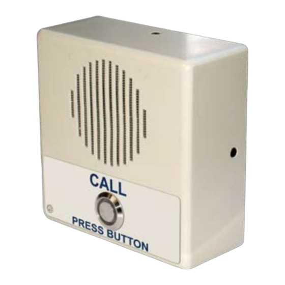
Page 19: Call Button And Indicator Light
You can press the Call button to terminate an active call whether the call was an incoming call ● or a call that was initiated by you. Figure 2-9. Call Button and Indicator Light Call button and indicator light Operations Guide 930260A CyberData Corporation... -
Page 20: Network Connectivity, And Data Rate
• This light is yellow at 10 Mbps. • It is orange at 100 Mbps. 2.2.5.1 Verify Network Activity The square, yellow Activity light blinks when there is network activity. Figure 2-10. Network Connector CyberData Corporation 930260A Operations Guide... -
Page 21: Rtfm Switch Jumper
4. The Intercom will announce the IP address. 5. After the Intercom has rebooted, remove the jumper from JP11. 6. Cycle power by disconnecting the PoE cable from J1 and plugging the PoE cable back into J1. Operations Guide 930260A CyberData Corporation... -
Page 22: Adjust The Volume
5. Cycle power by disconnecting the PoE cable from J1 and plugging the PoE cable back into J1. Figure 2-12. RTFM Switch Jumper 2.2.7 Adjust the Volume You will be only able to adjust the volume through the network configuration page. CyberData Corporation 930260A Operations Guide... -
Page 23: Configure The Intercom Parameters
Note Make sure that the PC is on the same IP network as the Intercom. You may also download CyberData’s VoIP Discovery Utility program which allows you to Note easily find and configure the default web address of the CyberData VoIP products. - Page 24 Shows the current volume level. Microphone Gain (0-9) Shows the current microphone gain level. Primary Dial-Out Shows the current primary dial-out number Link to the Intercom Setup web page. Link to the Network Setup web page. CyberData Corporation 930260A Operations Guide...
-
Page 25: Configure The Network Parameters
If you select Static, configure the remaining parameters indicated in Table 2-5 . If you select DHCP, go to Step IP Address* Enter the Static IP address. Subnet Mask Enter the Subnet Mask address. Operations Guide 930260A CyberData Corporation... - Page 26 Intercom if appropriate. 4. Connect the Intercom to the target network. 5. From a system on the same network as the Intercom, open a browser with the new IP address of the Intercom. CyberData Corporation 930260A Operations Guide...
-
Page 27: Set Up The Intercom
Installing the VoIP Indoor Intercom Configure the Intercom Parameters 2.3.3 Set up the Intercom 1. Click the Intercom Setup button to open the Intercom Setup page. See Figure 2-15. Figure 2-15. Intercom Setup Operations Guide 930260A CyberData Corporation... - Page 28 Intercom audio quality and volume. Click on this button to do an audio test. Generates a voice message for testing the Intercom audio quality and volume. Link to the Home page. Link to the Network Setup page. CyberData Corporation 930260A Operations Guide...
- Page 29 Table 2-6. Intercom Setup Parameters Web Page Item Description Link to the SIP Setup page. Link to the Sensor Setup page. Link to the Upgrade Firmware page. 3. After changing the parameters, click Save Settings. Operations Guide 930260A CyberData Corporation...
-
Page 30: Configure The Sip Parameters
Remote SIP Port* Enter the Remote SIP Port number (default 5060). Local SIP Port* Enter the Local SIP Port number (default 5060). SIP User ID* Enter the SIP User ID (up to 25 alphanumeric characters). CyberData Corporation 930260A Operations Guide... - Page 31 Link to the Intercom Setup page. Link to the Network Setup page. Link to the Upgrade Firmware page. Link to the Home page. 3. After changing the parameters, click Save Settings. Operations Guide 930260A CyberData Corporation...
-
Page 32: Configure The Sensor Setup Parameters
Select Yes to loop an audio file out of the Interfom speaker until the sensor is deactivated. Play Audio Remotely Select Yes to call a preset extension and play a pre- recorded audio file (once). Dial Out Extension Enter the button dial-out extension number. CyberData Corporation 930260A Operations Guide... - Page 33 Link to the Intercom Setup page. Link to the Network Setup page. Link to the Upgrade Firmware page. Link to the Home page. 3. After changing the parameters, click Save Settings. Operations Guide 930260A CyberData Corporation...
-
Page 34: Upgrade The Firmware And Reboot The Intercom
If you do not already have a TFTP server running on your network, see Appendix B, "Setting up a TFTP Server". 2. Retrieve the latest Intercom firmware from the CyberData website: http://www.cyberdata.net/support/voip/intercom.html 3. Unzip the Intercom version file. This file may contain the following: •... - Page 35 Therefore, in the case of a firmware upgrade to version 3.3.0 or later, CyberData recommends that you go to the Intercom Setup page and make sure the following values are set properly.
-
Page 36: Reboot The Intercom
To reboot a Intercom, log in to the web page as instructed in Section 2.3.1, "Log in to the Configuration Home Page". 1. Click Upgrade Firmware to open the Firmware Upgrade page (Figure 2-19). Figure 2-19. Reboot System Section 2. Click Reboot. A normal restart will occur. CyberData Corporation 930260A Operations Guide... -
Page 37: Appendix A Mounting The Intercom
Before you mount the Intercom, make sure that you have received all the parts for each Intercom. Refer to Table A-1. Table A-1. Drop Ceiling Mounting Components (Part of the Accessory Kit) Quantity Part Name Illustration 6-32 x 1" Pan head phillips wood screw Plastic ribbed anchor Operations Guide 930260A CyberData Corporation... - Page 38 Mount the Intercom Figure A-20 shows how to properly mount the VoIP Intercom. Figure A-20. Mounting From Microphone To J5 From Speaker From Pushbutton To J2 To J6 CyberData Corporation 930260A Operations Guide...
-
Page 39: Appendix B Setting Up A Tftp Server
B.1.3 In a Solarwinds Server Environment You can find several options online for setting up a Solarwinds server. This example explains how to use the Solarwinds freeware TFTP server, which you can download at: http://www.cyberdata.net/support/voip/solarwinds.html Operations Guide 930260A CyberData Corporation... - Page 40 Set up a TFTP Server CyberData Corporation 930260A Operations Guide...
-
Page 41: Appendix C Troubleshooting/Technical Support
Phone: 831-373-2601, Extension 136 Email: RMA@CyberData.net When returning a product to CyberData, an approved CyberData RMA number must be printed on the outside of the original shipping package. No product will be accepted for return without an approved RMA number. Send the product, in its original package, to the following address:... -
Page 42: Warranty
CyberData warrants its product against defects in material or workmanship for a period of two years from the date of purchase. Should the product fail within the warranty period, CyberData will repair or replace the product free of charge. This warranty includes all parts and labor. -
Page 43: Index
Web interface 15 to version 3.3.0 27 configuration home page 15 where to download the latest firmware 27 CyberData contact information, corporate, sales, tech where to get the latest firmware 26 support, service 33 firmware upgrades 31 flash button LED (door sensor) 24... - Page 44 20 activate on button press 20 activation duration 20 on button press timeout 20 network activity, verifying 12 remote SIP port 22 network configuration of intercom 17 reset test function management switch 13 CyberData Corporation 930260A Operations Guide...
- Page 45 TFTP server 4, 31 unregister, from SIP server 23 user ID for SIP server login 23 SIP 22 username changing for web configuration access 19 default for web configuration access 15 restoring the default 15 Operations Guide 930260A CyberData Corporation...
- Page 46 CyberData Corporation 930260A Operations Guide...
Need help?
Do you have a question about the 011030 and is the answer not in the manual?
Questions and answers