Table of Contents
Advertisement
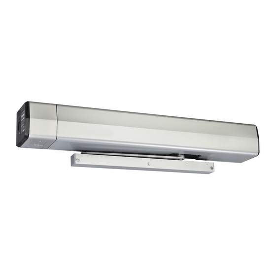
ASSA ABLOY
6060 / 6070
5
4
Item No. Description
1
Motor (6000M)
2
Cover (6000COV)
3
Control Inverter (6000IN)
4
Power Supply 24VDC (6000SUP)
5
Closer Assembly (7500LAP)
6
Unitrol Arm - standard reveal (6660-1); deep reveal (6670-1)
Door Swing 85°
Minimum
Door Width
Model No. Reveal Type
6060
Standard
6070
Tools required:
• Allen wrench set (inch)
• Flat blade screwdriver (potentiometer & terminal size)
• Screwdriver (Phillips size 2)
• Tape ruler
• Power drill
Use screw pack and hardware provided to mount operator.
WARNING: To reduce the risk of injury to person,
use this operator only with Pedestrian Swing doors.
For Indoor Use Only.
Copyright © 2015 Yale Security Inc., an ASSA ABLOY Group company. All rights reserved.
Reproduction in whole or in part without the express written permission of Yale Security Inc. is prohibited.
1
6
90°
95° 100° 105° 110°
36"
35"
34"
34"
33"
Reveal Depth
2-1/4" to 4-3/4"
Deep
4-13/16" to 7-3/8"
Installation and Instruction Manual
3
33"
Reveals less than
2-1/4" may be achieved
by field cutting adjusting rod.
• Center punch
• Wire stripper
• #7 drill 1/4-20 tap (metal frame install)
!
Ø3/8 drill (door sex bolt install)
ETL certified; conforms to ANSI/UL standard
325 for automatic closing doors and UL10C
Positive Pressure Fire Test for Door Assemblies.
Certified to ANSI/BHMA A156.19 for Low Energy
Door Operators.
6000 Series
Power Operator
2
Reveal
Adjusting Rod
80-9360-1003-020 (08-15)
5-13/32"
2-3/16"
Advertisement
Table of Contents

Subscribe to Our Youtube Channel
Summary of Contents for Norton 6000 Series
- Page 1 6000 Series Power Operator Installation and Instruction Manual ASSA ABLOY 6060 / 6070 Item No. Description Motor (6000M) Cover (6000COV) Reveal Control Inverter (6000IN) Power Supply 24VDC (6000SUP) Closer Assembly (7500LAP) Unitrol Arm - standard reveal (6660-1); deep reveal (6670-1) 5-13/32”...
- Page 2 Note: Flags included in this instruction sheet show a Pull side installation instead of a Push side installation. Use video segments for reference only. For assistance, contact Norton Technical Product Support at 800-438-1951 Ext 4706. ASSA ABLOY 3000 Highway 74 East • Monroe, NC 28112 Tel: 800-438-1951 Ext 4706 •...
- Page 3 ASSA ABLOY Door Prep Frame Hollow Metal Door Frame Reinforcing Reinforcing Frame Door 1/8" Material Recommended Min. Required 12 Ga. 12 Ga. 18 Ga. .1046 .1046 .0478 Templating is based on 1/8" gap between door and frame. (2.66) (2.66) (1.21) 14 Ga.
- Page 4 ASSA ABLOY IMPORTANT INSTALLATION INSTRUCTIONS 1) READ AND FOLLOW ALL INSTALLATION 3) Remove, or make inoperative, all locks (unless INSTRUCTIONS. mechanically and/or electrically interlocked to the 2) Install only on a properly operating and balanced door. A power unit) that are connected to the door before door that is operating improperly could cause severe installing the operator.
- Page 5 ASSA ABLOY Initial Wall Prep Blocking (supplied by others) is required for proper support of See page 24 for removable operator. Thickness is dependent upon Frame Return. template. Material must comply with local codes. A. For wood framing, screw blocking into wall studs. Frame Return B.
- Page 6 ASSA ABLOY Remaining Back Plate Screws Drill #7 and tap 1/4-20 Machine Screws or Self Drilling Screws (7 places). B. Install (7) 1/4-20 x 1” screws into Concealed holes drilled in Step 3A. Leave Wiring Holes 1/4” gap between bottom of “Closer”...
- Page 7 ASSA ABLOY Prep Door for Shoe Door Opening Dim “B” Angle 85° 13-1/4” 90° 12-5/8” Frame Rabbet 1-13/16” 12-0” 95° 4-1/8” DIM “B” 100° 11-1/2” A. Using template, 105° 11-1/8” locate and prepare Edge of Frame 110° 10-3/4” See page 24 holes in door.
- Page 8 ASSA ABLOY Assemble Arm to Pinion A. i)Slide Adjusting Rod into Tube of Arm Slide and Main Arm Tube Assembly. ii) Place square of Main Arm onto pinion with pinion flat and arm marking as shown below. Pinion Flat Arm Slide Tube Arm Marking Adjusting Rod...
- Page 9 ASSA ABLOY Closer Spring Force Adjustment Slowly increase closer power until door closes consistently. Stronger Weaker NOTE: A closer set to the ADA required 5 lbs opening force may not be strong enough to close the door due to latching hardware, air pressure, or frame issues.
- Page 10 ASSA ABLOY Incoming Power Connection Secure Incoming Power Low voltage / 120VAC Insert Signal 24VDC Power Screw (Dry) Power Inputs Contacts Outputs Line Neutral Control Wiring Wire Ground Screw Surface (Green) Mounted Conduit Shown Concealed Conduit Shown Low voltage / Incoming Power Control Wiring D.
- Page 11 ASSA ABLOY Set Home and Open Positions A. With door closed and 3-position switch on end of back plate in the “OFF” position, use joystick to scroll down menu on LCD screen to “Home”. B. Push in on joystick to activate menu feature. Display changes to “Set Close Limit”.
- Page 12 ASSA ABLOY General Electrical Information Powered A. Power inputs at Power Input Connection and Circuit Output Power Output Contacts must be made with Breaker Contacts copper wire only. B. Maximum wire size: 12 AWG at Power Input connection 14 AWG at all other terminals. C.
- Page 13 ASSA ABLOY Controller Interface Description Screen Display Adjustments Default Description Mount: Push or Pull Pull Side of opening operator is mounted on Turn on or off Push N Go feature.If On, a slight push or pull of Push: OFF or PushNGo the door starts it automatically opening.
- Page 14 ASSA ABLOY Factory Pre-Wiring of Connections 120VAC Signal 24VDC Power (Dry) Power Inputs Contacts Outputs Line Neutral Aux1 Pres Det Aux2 Door Toggle Aux1 Aux3 Aux2 No Conn Blow Open Basic Wiring Diagrams Using Factory Pre-Wired Connection Wall Switch, Card Reader, Key Switch, etc.
- Page 15 ASSA ABLOY Fail Safe Electric Strike or Electromagnetic Lock 24VDC Wiring Change Factory Pre-Wiring from Illustration A to Illustration B (more NO to NC) Fail Safe Electric Strike 24VDC Wiring 24VDC Doors are normally closed and Ÿ Electric Strike latched. (Fail Secure) Activating switch will unlock Ÿ...
- Page 16 ASSA ABLOY Electric Dogging Exit Device Wiring Change Factory Pre-Wiring from Illustration A to Illustration B (more NO to NC) Electric Dogging Exit Device Wiring Doors are normally closed and latched. Ÿ Turning key switch ON will apply power to 24VDC Electric Dogging Exit Ÿ...
- Page 17 ASSA ABLOY Electric Latch Retraction Exit Device Wiring Change Factory Pre-Wiring from Illustration A to Illustration B Electric Latch Retraction Exit 120 VAC Device Wiring Controller - 782 (Yale) Ÿ Doors are normally closed and latched. Latch Retraction Exit Device Activating switch will retract exit device Ÿ...
- Page 18 ASSA ABLOY Radio Frequency Standard Function Wiring (can be ordered pre-wired to this RF wiring) If installing in the field, change Factory Pre-Wiring from Illustration A to Illustration B Radio Frequency Standard Function Ÿ Doors are normally closed. Activating wireless switch or hand Ÿ...
- Page 19 ASSA ABLOY This Page Left Blank Copyright © 2015 Yale Security Inc., an ASSA ABLOY Group company. All rights reserved. Reproduction in whole or in part without the express written permission of Yale Security Inc. is prohibited. Page 19 80-9360-1003-020 (08-15)
- Page 20 ASSA ABLOY Vestibule Function Wiring Using Factory Pre-Wiring INSIDE DOOR Inside Switch Aux1 Pres Det Aux2 Wall Switch, Card Reader, Key Switch, etc. Door Toggle (Normally Open Momentary dry contacts) Aux1 Aux3 Vestibule Function Wiring Aux2 Ÿ Doors are normally closed and latched. No Conn Activating outside door switch will open the outside door.
- Page 21 ASSA ABLOY Troubleshooting Guide Issue Seen Solution 1) Adjust Latch and/or Sweep valves on closer clockwise or 2) Decrease Closing Door closing too fast Speed on controller (see page 10) 1) Adjust Latch and/or Sweep valves on closer counterclockwise or 2) Increase Door closing too slow Closing Speed on controller (see page 10) 1) Repeat Home process (see page 8), 2) Increase Obst Delay, 3) Adjust...
- Page 22 ASSA ABLOY 433MHz Receiver User’s Guide Antenna Wire Blue LED Red LED Terminal In Toggle Setting (1-ON), the 0.5 second 10 second Strip Hold Time is inactive. Either Pulse Setting Pulse Setting setting for #2 dip switch will have the same result. Learn Description Function...
- Page 23 ASSA ABLOY This Page Left Blank Copyright © 2015 Yale Security Inc., an ASSA ABLOY Group company. All rights reserved. Reproduction in whole or in part without the express written permission of Yale Security Inc. is prohibited. Page 23 80-9360-1003-020 (08-15)
- Page 24 ASSA ABLOY Removable Template Do not scale drawing. Ÿ Left hand door shown. Ÿ All dimensions given in inches (mm). Ÿ Maximum frame reveal is 6-7/8” (175 mm) for Ÿ this application. Copyright © 2015 Yale Security Inc., an ASSA ABLOY Group company. All rights reserved. Reproduction in whole or in part without the express written permission of Yale Security Inc.
Need help?
Do you have a question about the 6000 Series and is the answer not in the manual?
Questions and answers
how to remove remaining cover where electrical connection comes in
To remove the remaining cover on a Norton 6000 Series where the electrical connection is located:
1. If using a surface mount power input, remove the appropriate shaded area from the cover.
2. Repaint cut edges as needed to prevent corrosion.
3. Place the cover over the unit.
4. Secure it with the six 6-32 screws that were previously removed.
This answer is automatically generated