
Related Manuals for Carel pCO5+


Summary of Contents for Carel pCO5+
- Page 1 pCO5+ Programmable Controller User manual NO POWER & SIGNAL CABLES TOGETHER READ CAREFULLY IN THE TEXT! I n t e g r a t e d C o n t r o l S o l u t i o n s &...
- Page 3 The technical specifi cations shown in the manual may be changed without prior warning. The liability of CAREL in relation to its products is specifi ed in the CAREL general contract conditions, available on the website www.CAREL.com and/or by specifi c agreements with customers;...
- Page 4 pCO5plus +0300020EN rel. 1.2 - 07.11.2013...
-
Page 5: Table Of Contents
Content 1. INTRODUCTION 8. TECHNICAL SPECIFICATIONS Programmability ....................7 pCO5+ Technical Specifi cations ..............46 Functional layout ....................8 Conformity to standards ................50 Terminals........................9 Models ........................50 BMS port expansion cards ................9 Connectors ......................50 Fieldbus port expansions cards ...............10 9. APPENDIX External modules ....................11 Smart Key: operating instructions ............51 2. - Page 6 pCO5plus +0300020EN rel. 1.2 - 07.11.2013...
-
Page 7: Introduction
- NO or NC relay outputs; available on the market. - USB ports; - optically-isolated/non-optically-isolated built-in serial ports; The pCO5+ controller has been developed by CAREL to provide solutions - built-in display. • to a host of applications in air-conditioning, refrigeration and HVAC/R in various kinds of connectors (spring, screw, etc.). -
Page 8: Functional Layout
1.2 Functional layout The fi gure below shows the functional layout of an air handling unit. Damper actuators and valve actuators are fi eld devices that communicate through Fieldbus 1 (ref. C). Fieldbus 2 (ref. E) is the medium through which the serial probes communicate the values measured, and through which the humidifi... -
Page 9: Terminals
Terminals Note: All instruction sheets can be downloaded from www.carel. com in the “Documentation” section. Code Description Notes The pGD Touch 4.3” graphics terminal belongs to the family of touchscreen terminals, PGDT04000F*** designed to simplify and make more intuitive the interfacing of users with the controllers pGD Touch 4.3”... -
Page 10: Fieldbus Port Expansions Cards
Allows connecting to a LonWorks® TP/FT 10 network. The program resides in the fl ash PCO10000F0 memory located in the socket, and can be programmed directly via the LonWorks® LonWorks® interface network using network installation and maintenance tools such as LonMaker™. (tech. -
Page 11: External Modules
• can be connected to the CPY terminal (code CPYTERM*) or to the supervisor network with Modbus® RTU or proprietary CAREL protocol. PCOUMI2000 Allows checking the main parameters of humidifi ers for OEM made by CAREL di- Interface for OEM rectly from the pCO controller. The values measured by the sensors (high level, (tech. -
Page 12: Design
2. DESIGN On the models where they are included, the front panel contains a display and a keypad with 6 backlit buttons that, when pressed individually or in combination, allow the following operations: • uploading an application program; • commissioning. During regular operation and depending on the application program installed, the terminal can be used: •... -
Page 13: Communication Ports
3. COMMUNICATION PORTS 3.1 Serial ports Compared to the pCO3, pCO5+ (and pCO5) controllers have a second BMS serial port on connector J25 (BMS2) and a second Fieldbus port on connector J26 (FBus2). pCO5+ Large and Extralarge boards still have connector J23, which is marked FBus2 like connector J26. -
Page 14: Port J26 Confi Guration
RS485 Fieldbus port are, due to the nature of the port, Master protocols (CAREL Master or Modbus RTU Master), although in special cases Slave protocols can be used (CAREL Slave or Modbus RTU Slave), adopting the necessary measures. Likewise, Slave protocols are applied on the RS485 BMS port, although under certain conditions Master protocols can also be used. -
Page 15: Installation
INSTALLATION 4.1 Mounting on DIN rail and dimensions The controller is designed to be mounted on a DIN rail. The fi gure below shows the dimensions for each size. Mounting: • place the controller on the DIN rail and press it down gently. The tabs at the back will snap into place and lock the controller. -
Page 16: Preliminary Operations
Non-optically-isolated serial port • Use only optional boards and connectors supplied by CAREL. This is the case of the serial ZERO - pLAN (J11), Fieldbus 2 (J23 and J26) and BMS2 if not optically isolated (on models with built-in ports that are not optically isolated). - Page 17 Case 1: Multiple boards connected to a Master/Slave network powered Optically-isolated serial port by the same transformer. This is a typical application of multiple boards This is the case of serial ONE - BMS1, serial TWO - Fieldbus 1 and the built- connected inside the same electrical panel.
-
Page 18: Connecting The Terminal
The typical connection for one terminal (e.g. PGD1) is made using a Case B: 2 terminals 6-pin telephone cable available from CAREL as an accessory (code Two terminals can be directly connected only on a Small model. Models S90CONN00*). The telephone connector provides both data transmission of other sizes require the second terminal to be powered separately. -
Page 19: Input/Output Labels
B.2 Distance 50< L< 200 m. 2: pCO controller in pLAN network Use 3 TCONN6J000 boards connected as shown in the fi gure. If a terminal is connected to a pCO controller which is itself connected to other controllers in a pLAN network, the terminal is directly powered L <... -
Page 20: I/O Table
4.7 I/O table pCO5+ Controllers pCOE I/O expansion card NTC input In Universal I/O In Analogue input(*) PTC input In Universal I/O PT500 input In Universal I/O PT1000 input In Universal I/O PT100 input max 2 max 3 max 4 max 3 max 3 In Universal I/O... -
Page 21: Small And Medium Pco5+: Connecting Terminals
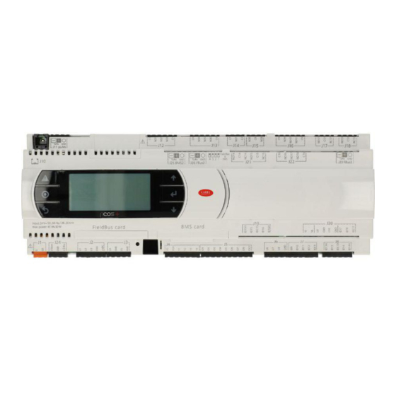
4.8 Small and Medium pCO5+: connecting terminals 13 14 J1 5 J1 2 J1 3 J1 4 J11 pLAN J2 5 BMS2 J2 6 FBus2 FieldBus card B M S card Fig. 4.q J1 7 J1 2 J1 3 J1 4 J11 pLAN J2 5 BMS2 J2 6 FBus2... -
Page 22: Large And Extralarge Pco5+: Connecting Terminals
4.9 Large and Extralarge pCO5+: connecting terminals N.C. Model J11 pLAN J23 FBus2 J25 BMS2 J26 FBus2 N.O. Model FieldBus card B M S card Fig. 4.s J11 pLAN J23 FBus2 J25 BMS2 J26 FBus2 FieldBus card B M S card Fig. -
Page 23: Pco5+ With Built-In Driver: Connecting Terminals
4.10 pCO5+ with built-in driver: connecting terminals pCO5+ controllers come in two models, with one or two built-in drivers for electronic expansion valves. J11 pLAN J25 BMS2 J26 FBus2 driver FieldBus card B M S card Fig. 4.u Ref. Description Ref. -
Page 24: Pco5+ Terminals Description
4.12 pCO5+ terminals description Ref. Term. Label Description J12-1 Common for relays 1, 2, 3 Please refer to the fi gures in the preceding pages regarding the pCO5+. J12-2 Normally open contact, relay 1 J12-3 Normally open contact, relay 2 J12-4 Normally open contact, relay 3 J12-5... - Page 25 Only for pCO5+ built-in driver: J27-1 Electronic expansion valve 1 control (see “Electro- J27-2 J27-3 nic valve connection”). J27-4 J28-1 J28-2 Electronic expansion valve 2 control (see “Electro- J28-3 nic valve connection”). J28-4 J30-1 VBAT J30-2 Power from external Ultracap module J30-3 J29-1 Common for power supply to probes...
-
Page 26: Input/Output Connections
INPUT/OUTPUT CONNECTIONS 5.1 Power supply Max. number of connectable analogue inputs The maximum number of analogue inputs that can be connected to the The fi gure below shows the power supply connection diagram. Use universal inputs/outputs depends on the type used. a class II safety isolating transformer with short-circuit and overload protection. - Page 27 For details on the operating range see the data sheets supplied with the probes. The controller can be connected to all the CAREL DP* series active temperature input: 24 V 50...60 Hz / 28...36 V max. power: 45 VA/20 W...
- Page 28 The controller can be connected to all CAREL SPK* series active pressure FieldBus card B M S card probes or any commercially available pressure probes with 0 to 20 mA or 4 to 20 mA signals.
-
Page 29: Digital Inputs
Connecting fast digital inputs 5.3 Digital inputs The controller features digital inputs for connecting safety devices, Important: The wires connecting the fast digital inputs/counters alarms, device status indicators and remote switches. These inputs are all optically isolated from the other terminals. They can work at 24 Vac (+10/- must be shielded to avoid causing electromagnetic interference with the 15%) or at 28 to 36 Vdc (-20/+10%) (indicated with ID*), and some also at probe cables. - Page 30 Example of connection diagram (LARGE model): J1 9 FieldBus card B M S card 24 Vac Fig. 5.m FieldBus card B M S card 24 Vac Fig. 5.n 24 Vdc digital inputs The ID... digital inputs can be controlled at 24 Vdc. Example of connection diagram (LARGE model): input: 24 V 50...60 Hz / 28...36 V max.
-
Page 31: Optically-Isolated Analogue Outputs
230 Vac digital inputs Medium and Extralarge models feature one group of 230 Vac inputs (terminal J8), while Large models have two groups (on terminals J8 and J19). Each group consists of two digital inputs that can be powered at 230 Vac, indicated with IDH*, and two inputs that can be powered at 24 Vac/ Vdc, indicated with ID*. - Page 32 Example of connection diagram (LARGE model): eldBus card B M S card Vout Vout Vout Vout 24 Vac / 28...36 Vdc Vout Vout Fig. 5.s Max. number di optically-isolated analogue outputs (reference VG0) pCO5+ model Small/Medium/Extralarge Large Outputs Y1, Y2, Y3, Y4 Y1, Y2, Y3, Y4, Y5, Y6 pCO5plus +0300020EN rel.
-
Page 33: Connecting The Electronic Valve
Fbus2 port (J26) must have the same communication protocol (CAREL Standard Master or Modbus® Master), the same baud rate, stop bits and parity. The CAREL or Modbus protocol is selected automatically. The internal driver’s address is 198 (EVD Evolution’s default... -
Page 34: Digital Outputs
5.6 Digital outputs RELAY GROUPS FOR CONSECUTIVE COMMANDS (~100 ms) Electromechanical relay digital outputs pCO5+ pCO5+ Extra- The controller features digital outputs with electromechanical relays. For Large Large ease of installation, the common terminals of some of the relays have 9, 10, 11, 14, 15, 16, 14, 15, 16, 17,... -
Page 35: General Connection Diagram
1 (0/5 V) +5 V probe 2 (4/20 mA) probe 3 (0/1 Vdc or 4/20 mA) +VDC probe 4 Carel NTC probe 5 PT1000 digital output 1 digital output 2 digital output 3 analog output 1 (0...10 Vdc) analog output 2 (0...10 Vdc) -
Page 36: Start-Up
NC14 NC14 pGDE/pGD1 Shared ID15H NO15 ID15H NO15 IDC1 IDC1 ID15 ID15 IDC15 IDC15 NC15 CAREL devices in a pCO local area network (pLAN) without requiring NC15 ID16 ID16 ID16H ID16H NO10 NO16 NO10 NO16 ID10 ID10 NO11 NO17 NO11... -
Page 37: Setting The Terminal's Address And Connecting The Controller To The Terminal
Setting the pLAN address Power off the controller. Procedure: Press button A for 5 seconds; the pLAN address starts fl ashing. Press repeatedly or hold the button until reaching the desired address (e.g. 7), then remove the screwdriver. J11 pLAN Wait until the address starts fl... -
Page 38: Uploading Software
fi les to the NAND fl ash memory. establish the connection. The terminal can be either private or shared. As a rule, CAREL advises NOT to update the BOOT; CAREL always loads the BOOT best suited for the controller’s operation during construction. Only Smart key in very special cases will CAREL ask the user to update the BOOT. -
Page 39: Checking The Software Installed And Other Information
NAND fl ash memory Upload and Download UPLOAD can be performed in three diff erent ways: This type di memory is included on all pCO5+ controller versions. pCO Manager can be used to load any type of fi le to the NAND fl ash memory. manual mode: the user selects manual mode from the keypad, then It can be used, for example, to save the source fi... - Page 40 M E M O R I E S S T A T U S The ID number is a code, diff erent for each pCO manufactured by CAREL, and is available for use in future applications. Not all pCO units are given an ID number by CAREL;...
-
Page 41: Application Diagrams
APPLICATION DIAGRAMS The following are a series of diagrams illustrating which devices can be Heat pump connected to the pCO5+ and the accessory cards required, depending Power + on the type of application. PGD1* PSD0* PGD Touch Air handling unit CP*: schede controllo CP*: KUE humidifi... - Page 42 Chiller - Screw compressor To manage two refrigerant circuits, there are two options. Case 1: 2 pCO5 Medium controllers and pCO5+ with built-in electronic expansion valve driver. dispositivi dispositivi dispositivi Device Device Device PGD1* terze parti terze parti terze parti PGD1* PGD Touch INVERTER...
- Page 43 pCO5plus +0300020EN rel. 1.2 - 07.11.2013...
-
Page 44: Devices That Can Be Connected To The Pco5
- pGD1 terminal pGD2 - pGD3 terminal Aria terminal pCO in pLAN FCM series controllers EVD200 EVD Evolution CAREL slave devices (tLAN) CAREL slave devices (485) pCOexp 485 pCOexp tLAN μChiller2 expansion Hydronic fan coil and CANbus PlantVisorPRO local... - Page 45 Modbus Slave If Modbus Slave is active then CAREL Slave can be activated only on another serial port. The second Modbus extended on BMS2 (with 10000 integer variables) can work at the same time as the one activated on the other ports.
-
Page 46: Technical Specifications
TECHNICAL SPECIFICATIONS 8.1 pCO5+ Technical Specifi cations SMALL 13 DIN modules 110 X 227,5 X 60 mm Dimensions MEDIUM, LARGE, EXTRALARGE 18 DIN modules 110 X 315 X 60 mm BUILT-IN DRIVER 18 DIN modules 110 X 315 X 75 mm Mounting Can be mounted on DIN rail in accordance with DIN 43880 and IEC EN 50022 Material... - Page 47 MEDIUM/ BUILT-IN DRIVER/ SMALL LARGE EXTRALARGE - CAREL NTC probes (-50T90°C; R/T 10 kΩ±1% at 25°C) - NTC HT (0T150°C) - PTC (600Ω to 2200Ω) - PT500 (-100T300°C) - PT1000 (-100T400°C) 4 (2 on U1 to U5, 3 (2 on U1 to U5, - PT100 probes (-100T400°C)
- Page 48 Type 0 to 10 V optically-isolated on Y1 to Y6 Lmax 30 m SMALL, MEDIUM/ BUILT-IN DRIVER/EXTRALARGE Y1...Y4 a 0...10 V Maximum number Analogue outputs LARGE Y1...Y6 a 0...10 V Power supply External 24 Vac (+10/-15%) or 28 to 36 Vdc on VG(+), VG0(-) (*) Accuracy Y1...Y6 ±2% full scale...
- Page 49 CAREL: Two CAREL EXVs as for EVD EVOLUTION TWIN SPORLAN: SER(I) G, J, K Shielded 4-wire cable CAREL code E2VCABS*00, or AWG22 shielded 4-wire cable Lmax =10 m, or AWG14 shielded 4-wire cable Lmax = 50 Motor connection Digital input Digital input to be activated with voltage-free contact or transistor to GND.
-
Page 50: Conformity To Standards
P+5****C***** Optically-isolated BMS2/Optically-isolated Fieldbus2 P+5***0****** No USB port USB port P+5***A****** USB port P+5******0*** Without valve driver Valve P+5******1*** 1 CAREL valve driver driver P+5******2*** 2 CAREL valve drivers P+5*******0** Without terminal Built-in P+5*******E** Con PGD1 terminal terminal P+5********S* Small... -
Page 51: Appendix
9. APPENDIX 9.1 Smart Key: operating instructions Meanings of Buttons/Symbols Flashing: The key is connecting to the pCO. During this phase, which may last a few seconds, the start button is disabled. start Flashing: The key has detected the pCO and is checking the access rights. -
Page 52: Pco Manager: Operating Instructions
Installing pCO Manager Go to http://ksa.carel.com and, in the section pCO Sistema, select pCO_ manager. After you accept the general conditions of the software’s free use licence, a window will open from which you can download the fi le pCO_manager.zip. - Page 53 2) Enter the new value (e.g. 3) and click OK. The new value will appear in When the user has fi nished using Commissioning, whether for confi guration the column marked “scritto” [written]. To write the parameter to the pCO or monitoring purposes, the following fi...
-
Page 54: Pendrive: Operating Instructions
Menu access 9.3 Pendrive: operating instructions The following are the steps for accessing the pendrive management menu. Procedure: File extensions, names and contents Connect the pendrive to the master port. Various types of fi les can be uploaded and downloaded and are distinguished by their extension. - Page 55 UPLOAD non-volatile memory (.dev) Upload non volatile memory carel.com (.os file), unzip the .os file; UPLOAD the entire contents of the pCO Copy pCO upload • the [IUP] label can be followed by one or more “.iup” files.
- Page 56 Confi rm by selecting Prg. A screen is displayed requesting The display fl ashes to indicate that after loading the new BIOS the confi rmation to upload the non-volatile memory. Press Enter to controller is being reset. confi rm. Fig. 9.p Fig.
- Page 57 Download As mentioned above, the DOWNLOAD operation can be managed in two ways: Manual mode: follow the steps described in the paragraph “Automatic upload” and select manual operation. Then each fi le must be selected and downloaded. Autorun mode: prepare a fi le called “autorun.txt”, containing a string that identifi...
-
Page 58: Confi Guring Pcoweb/Pconet From A System Screen
When you select “PCONET settings” the following screen will appear: usual tools, i.e. BACset or web interface (pCOWeb only). Confi guration can be done either when using the Modbus protocol or the CAREL B A C n e t I D : protocol, but only on the BMS1 serial port. - Page 60 Agenzia / Agency: CAREL INDUSTRIES - Headquarters Via dell’Industria, 11 - 35020 Brugine - Padova (Italy) Tel. (+39) 049.9716611 - Fax (+39) 049.9716600 e-mail: carel@carel.com - www.carel.com...
Need help?
Do you have a question about the pCO5+ and is the answer not in the manual?
Questions and answers