
Related Manuals for Carel pCO2


Summary of Contents for Carel pCO2
- Page 1 Program for pCO¹ pCO and pCOC Modular Standard HP Chiller 1/4 screw compressor with Carel driver Manual version 1.0 – 25 September 2003 FLSTDmMSDE Program code:...
- Page 3 Do we want you to save you time and money? We can assure you that reading this manual to the full will ensure correct installation and safe use of the product described here. IMPORTANT WARNINGS BEFORE INSTALLING OR CARRYING OUT ANY JOBS ON THE APPLIANCE, CAREFULLY READ AND FOLLOW THE INSTRUCTIONS IN THIS MANUAL.
-
Page 5: Table Of Contents
CONTENT APPLICATIONS AND FUNCTIONS PERFORMED BY THE SOFTWARE ..................3 THE USER TERMINAL ....................................4 PLAN MANAGEMENT AMONG CARDS..............................6 HOW TO ASSIGN THE PLAN ADDRESSES ............................6 INSTALLING DEFAULT VALUES................................7 SELECTING THE LANGUAGE ................................. 7 LIST OF INPUTS/OUTPUTS..................................8 CHILLER-ONLY UNIT - MACHINE TYPE “0”... - Page 6 FREE COOLING CONTROL ................................35 19.2 ............................... 35 OOLING ACTIVATION CONDITION 19.3 ................................36 OOLING HERMOSTAT 19.4 ..............................37 OOLING DISABLING CONDITIONS 19.5 ON/OFF ................................37 OOLING VALVE 19.6 ON/OFF ......................38 OOLING VALVE WITH STEPPED CONDENSATION 19.7 ON/OFF ................... 39 OOLING VALVE WITH INVERTER CONTROLLED CONDENSATION 19.8...
-
Page 7: Applications And Functions Performed By The Software
Standard Chiller/HP modulare per compressore a vite con driver CAREL APPLICATIONS AND FUNCTIONS PERFORMED BY THE SOFTWARE Type of control unit AIR / WATER CHILLER • Chiller only • Chiller + Heat pump • Chiller + Freecooling WATER / WATER CHILLER •... -
Page 8: The User Terminal
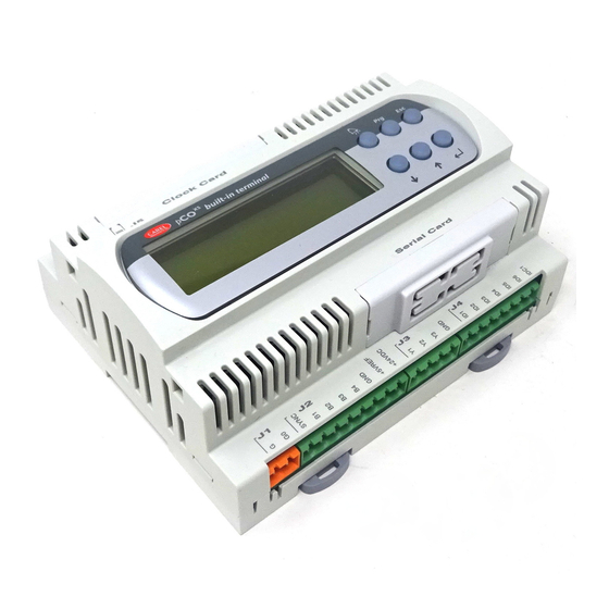
Standard Chiller/HP modulare per compressore a vite con driver CAREL THE USER TERMINAL The specified terminal has an LCD display (4 lines over 20 columns) and can be of two types: on board a built-in card with only 6 keys or external (connected by telephone cable) with 15 keys. - Page 9 Standard Chiller/HP modulare per compressore a vite con driver CAREL How to use the silicone rubber keys: ON/OFF key: for switching the unit on and off. ALARM key: to view the alarms on the display, cancel them and silence the...
-
Page 10: Plan Management Among Cards
ADDRESSING PCO2, EXTERNAL TERMINALS AND VALVE DRIVERS The following are the addresses to be set on the pCO2 cards, external terminals and valve drivers. If you are using the pCO1 cards, consult the previous paragraph for the cards only, whereas the following information does apply to the terminals and drivers. -
Page 11: Installing Default Values
When you have checked the connections between the cards and terminals, power up the pCO card/s* When the machine is powered up, the software automatically installs the default values selected by CAREL for all the chiller and driver configuration parameters. -
Page 12: List Of Inputs/Outputs
Standard Chiller/HP modulare per compressore a vite con driver CAREL LIST OF INPUTS/OUTPUTS Inputs and outputs are listed below based on unit type. A number has been associated with each type of machine. This number is the program's main parameter because it identifies the inputs and outputs configuration. Using this list of inputs and outputs, select the number you require from the numbers associated in the program configuration screens. -
Page 13: Chiller Unit + Heat Pump - Machine Type "1
Standard Chiller/HP modulare per compressore a vite con driver CAREL CHILLER UNIT + HEAT PUMP – MACHINE TYPE “1” 6.2.1 DIGITAL INPUTS Chiller unit + heat pump MACHINE TYPE “1” pCO2 MEDIUM pCO1 MEDIUM pCOC MEDIUM Master (Address 1) Slave (addresses 2/3/4) -
Page 14: Chiller Unit With Freecooling - Machine Type "2
Standard Chiller/HP modulare per compressore a vite con driver CAREL CHILLER UNIT WITH FREECOOLING – MACHINE TYPE “2” 6.3.1 DIGITAL INPUTS Chiller unit with freecooling MACHINE TYPE “2” pCO2 MEDIUM pCO1 MEDIUM pCOC MEDIUM Master (Address 1) Slave (addresses 2/3/4) -
Page 15: Chiller-Only Unit - Machine Type "3
Standard Chiller/HP modulare per compressore a vite con driver CAREL WATER/WATER UNIT WITH MAX. 4 SCREW COMPRESSORS (UP TO 4 CAPACITY STAGES PER COMPRESSOR) CHILLER-ONLY UNIT – MACHINE TYPE “3” 6.4.1 DIGITAL INPUTS Chiller-only unit MACHINE TYPE “3” pCO2 MEDIUM... -
Page 16: Chiller Unit + Heat Pump With Gas Reversing - Machine Type "4
Standard Chiller/HP modulare per compressore a vite con driver CAREL CHILLER UNIT + HEAT PUMP WITH GAS REVERSING – MACHINE TYPE “4” 6.5.1 DIGITAL INPUTS Chiller unit + heat pump with gas reversing MACHINE TYPE “4” pCO2 MEDIUM pCO1 MEDIUM... -
Page 17: Chiller Unit + Heat Pump With Water Reversing - Machine Type "5
Standard Chiller/HP modulare per compressore a vite con driver CAREL CHILLER UNIT + HEAT PUMP WITH WATER REVERSING – MACHINE TYPE “5” 6.6.1 DIGITAL INPUTS Chiller + Heat pump with water reversing MACHINE TYPE "S" pCO2 MEDIUM pCO1 MEDIUM pCOC MEDIUM... -
Page 18: List Of Parameters
Standard Chiller/HP modulare per compressore a vite con driver CAREL LIST OF PARAMETERS The table below describes program parameters along with the following additional information: screen code (screens have a code in the top right corner) to make identifying the parameter easier (screen), factory setting, upper and lower limits of the range within which values can be effected, unit of measurement, and an empty column for writing the desired value. - Page 19 Standard Chiller/HP modulare per compressore a vite con driver CAREL DESCRIPTION OF PARAMETER SCREEN MASTER FACTORY USER RANGE MEASU- SLAVE VALUE VALUE REMENT UNIT Delayed power up between pump and compressors 0 to 999 seconds Delayed power down of main pump...
- Page 20 Standard Chiller/HP modulare per compressore a vite con driver CAREL DESCRIPTION OF PARAMETER SCREEN MASTER FACTORY USER RANGE MEASU- SLAVE VALUE VALUE REMENT UNIT Step 1 - Relay 1 logic OFF/ON Step 1 - Relay 2 logic OFF/ON Step 1 - Relay 3 logic...
- Page 21 Standard Chiller/HP modulare per compressore a vite con driver CAREL DESCRIPTION OF PARAMETER SCREEN MASTER FACTORY USER RANGE MEASU- SLAVE VALUE VALUE REMENT UNIT Pump status in case of antifreeze alarm Pump ON Pump ON /Pump OFF Solenoid-valve management set-point 80.0...
- Page 22 Standard Chiller/HP modulare per compressore a vite con driver CAREL DESCRIPTION OF PARAMETER SCREEN MASTER FACTORY USER RANGE MEASU- SLAVE VALUE VALUE REMENT UNIT Integral time of threshold for condensation high 0 to 25.5 seconds temperature protection during chiller operation Threshold for condensation high temperature 75.0...
-
Page 23: Screens
Standard Chiller/HP modulare per compressore a vite con driver CAREL SCREENS Screens can be divided into 5 categories: • USER screens, not password protected: they appear in all loops except “prog” and “menu+prog” and show probe values, alarms, hours of operation of the devices, time and date, and can be used to set temperature and humidity set points and for clock set-up. They are marked with the “!”... -
Page 24: Electronic Expansion Valve
Standard Chiller/HP modulare per compressore a vite con driver CAREL ELECTRONIC EXPANSION VALVE The EV Driver module for piloting the electronic expansion valves (EEV) for the pLAN network, makes it possible to control intake superheating to enable the refrigerating unit to operate more efficiently and with greater versatility. -
Page 25: Special Function "Ignore
Standard Chiller/HP modulare per compressore a vite con driver CAREL 9.1.3 Super-heat set point in mode CH/HP/DF (F4/F5/F6) Set point for superheating control. We advise you not to use values below 3°C Superheating control dead band. Control is not enabled for temperatures in the range Sheat Set – SH Dead band and Sheat Set + SH Dead band For example, a dead band value of 1°C, with a set point of 5°C, means that superheating can vary from 4°C and 6°C without the control... -
Page 26: Control
Standard Chiller/HP modulare per compressore a vite con driver CAREL 10 Control There are two different modes for controlling the control thermostat: • Control according to the water temperature values measured by the probe located at the evaporator inlet. •... -
Page 27: Outlet Temperature Control
Standard Chiller/HP modulare per compressore a vite con driver CAREL 10.2 Outlet temperature control Inputs used: • Water temperature at evaporator outlet Parameters used: • Type of unit • Total number of compressors • Type of compressor capacity control •... -
Page 28: Control Of Water/Water Chiller Unit With Gas Reversing Heat Pump
Standard Chiller/HP modulare per compressore a vite con driver CAREL 10.4 Control of water/water chiller unit with gas reversing heat pump Inputs used: • Water temperature at evaporator inlet • Water temperature at evaporator outlet • Water temperature at condenser inlet •... -
Page 29: Types Of Controlled Compressors
Standard Chiller/HP modulare per compressore a vite con driver CAREL 11 Types of controlled compressors 11.1 Stepped capacity control A maximum number of four compressors are managed, with a maximum of four capacity control steps each. Capacity control is achieved by three relay outputs which, when suitably commanded, short-circuit the refrigerant thrust by the compressor, varying its capacity and, therefore, the power input into the circuit. -
Page 30: Stepped Capacity Control With Control At Inlet
Standard Chiller/HP modulare per compressore a vite con driver CAREL 11.2 Stepped capacity control with control at inlet A description of stepped capacity control of 4 compressors with four capacity control steps each: C1P1 C2P1 C3P1 C4P1 Evaporator inlet temperature... -
Page 31: Continuous Capacity Control
Standard Chiller/HP modulare per compressore a vite con driver CAREL 11.4 Continuous capacity control A maximum number of four compressors are managed, with continuous capacity control. The compressor's capacity is controlled by two relay outputs, which, when suitably controlled, enable compressor power to be increased or reduced, varying the capacity of the compression chamber. -
Page 32: Continuous Capacity Control With Control At Outlet
Standard Chiller/HP modulare per compressore a vite con driver CAREL 11.5 Continuous capacity control with control at outlet Temperature control with compressors on continuous capacity control can occur only if control at outlet is selected, according to the temperature values measured by the probe located at evaporator outlet. -
Page 33: Compressor Rotation
Standard Chiller/HP modulare per compressore a vite con driver CAREL 11.5.2 Power-up of compressors (temperature above point E) The compressors are powered up in sequence at a rate calculated by the set time required to reach maximum power. As there is no absolute reference concerning the value of input power, as soon as it is started, the compressor performs a forced discharge cycle for a set time (capacity control relays energised continuously according to the power discharge configuration). -
Page 34: Starting A Single Compressor
Standard Chiller/HP modulare per compressore a vite con driver CAREL 13 Starting a single compressor 13.1.1 Description of operation The start-up stages are described in the following graph Thermostat Liquid solenoid Ventilating unit Compressor Delayed power-up 13.2 Starting the compressor motor 13.2.1... -
Page 35: Forced Capacity Control
Standard Chiller/HP modulare per compressore a vite con driver CAREL 14 Forced capacity control Inputs used • Water temperature at evaporator outlet • Compressor delivery temperature • Condensation pressure Parameters used • High delivery temperature prevention threshold • High delivery temperature prevention differential •... -
Page 36: Solenoid-Valve Management
Standard Chiller/HP modulare per compressore a vite con driver CAREL 15 Solenoid-valve management. Inputs used: • Compressor delivery temperature Parameters Used : • Solenoid-valve activation threshold • Solenoid-valve differential Outputs used : • Economizer solenoid-valve, oil-cooler, liquid-injection 15.1.1 Description of operation A digital output is provided for controlling an economizer solenoid-valve, oil-cooler and liquid injection. -
Page 37: Condensation Control
Standard Chiller/HP modulare per compressore a vite con driver CAREL 17 Condensation control Condensation can be performed in the following modes: • ON/OFF linked to compressor operation (without pressure transducers) • ON/OFF or modulating linked to reading by the pressure transducer (if the high pressure transducers were enabled) •... -
Page 38: Defrosting Control For Water/Air Machines
Standard Chiller/HP modulare per compressore a vite con driver CAREL 18 Defrosting control for water/air machines Inputs used: • battery B3 temperature (can be used as a pressure switch) • high pressure B7 • Input for defrosting pressure switch 1 Parameters used : •... -
Page 39: Free Cooling Control
Standard Chiller/HP modulare per compressore a vite con driver CAREL 19 Free Cooling Control Inputs used • Water temperature at evaporator outlet • Water temperature at inlet of Free Cooling battery • Outside air temperature Parameters used • Type of unit •... -
Page 40: Free Cooling Thermostat
Standard Chiller/HP modulare per compressore a vite con driver CAREL 19.3 Free Cooling Thermostat Free Cooling control exploits the calculated control set point values (taking into account any compensation) and the set Free Cooling control differential. The control is based on the water temperature measured by the probe located at the evaporator outlet, considering the effective supply of cold of the Free Cooling exchanger according to the different external temperature conditions. -
Page 41: Free Cooling Disabling Conditions
Standard Chiller/HP modulare per compressore a vite con driver CAREL The purpose of this time is to delay the activation of the compressors in order to give Free Cooling sufficient time to reach the steady state conditions and take the machine's yield to nominal value. Only after this time has elapsed, and with the main thermostat dissatisfied, the compressors are commanded to operate. -
Page 42: Free Cooling On/Off Valve With Stepped Condensation
Standard Chiller/HP modulare per compressore a vite con driver CAREL 19.5.2 Proportional + integral control Free Cooling Differential Free Cooling Differential Free Cooling ON/OFF Valve Evaporator Outlet Free Cooling set point Temperature If temperature conditions favour Free Cooling control, the Free Cooling ON/OFF valve will be activated as soon as temperature exceeds the activation threshold of the individual step, identified by a temperature value of: Control Set point + 5.0% Free Cooling Differential... -
Page 43: Free Cooling On/Off Valve With Inverter Controlled Condensation
Standard Chiller/HP modulare per compressore a vite con driver CAREL 19.6.2 Proportional + integral control Free Cooling Differential Free Cooling Differential 5.0 % Free Cooling ON/OFF Valve Evaporator Outlet Temperature Free Cooling set point Here is an example of Free Cooling control with ON/OFF valve and three condensation steps. -
Page 44: Volt Free Cooling On/Off Valve
Standard Chiller/HP modulare per compressore a vite con driver CAREL 19.7.2 Proportional + integral control Free Cooling Differential Free Cooling Differential 5.0 % 10 Volt Free Cooling Inverter Ramp 0 ON/OFF Valve to 10V 0 Volt Free Cooling set Evaporator Outlet... -
Page 45: Volt Free Cooling Valve With Inverter Controlled Condensation
Standard Chiller/HP modulare per compressore a vite con driver CAREL 19.9.2 Proportional + integral control Free Cooling Differential Free Cooling Differential 10 Volt Free Cooling Valve 0 to 10 V 0 Volt Evaporator Outlet Free Cooling set point Temperature The devices, whether they are valve or fans, will be activated in the second half of the control differential through the effect of the integrating control. - Page 46 Standard Chiller/HP modulare per compressore a vite con driver CAREL Example Control set point 12.0ºC Free Cooling Differential 4.0ºC Free Cooling valve % threshold Condensation inverter % threshold: Proportional area for control of Free Cooling valve = 10.0 - 11.6 ºC Control Set point - Free Cooling Differential/2 = 10.0ºC...
-
Page 47: Alarms
Standard Chiller/HP modulare per compressore a vite con driver CAREL 20 Alarms Alarms are divided into three categories Warning-only alarms (only warning on display and buzzer, warning on display, buzzer, alarm relay) Circuit alarms (only disable relevant circuit, warning on display, buzzer, alarm relay) Serious alarms (disable whole system, warning on display, buzzer, alarm relay) 20.1... -
Page 48: Antifreeze Control
Standard Chiller/HP modulare per compressore a vite con driver CAREL 20.5 Antifreeze control Inputs used: • Water temperature at evaporator outlet • Water temperature at condenser outlet Parameters Used : • Enable evaporator outlet probe • Enable condenser outlet probe •... -
Page 49: Pco Alarms Table
Standard Chiller/HP modulare per compressore a vite con driver CAREL 20.6 pCO alarms table Code Alarm description Reset Delay Separation Compressor Fans Pump System Serious Alarm Manual Mst/Slv Phase Monitor Alarm Manual Mst/Slv Evaporator Pump thermal Cutout Manual Condenser Pump thermal Cutout... -
Page 50: Alarm Log
The pCO* boards’ considerable buffer space means events can be saved in the STANDARD log, which is always available on the various boards. If there is no clock card (optional extra on pCO1 and pCOC, built-in feature on pCO2), the STANDARD log just gives the alarm code. -
Page 51: List Of Alarm Log Codes
Standard Chiller/HP modulare per compressore a vite con driver CAREL 21.3 List of alarm log codes AL:001 Unit No. 1 Offline AL:002 Unit No. 2 Offline AL:003 Unit No.3 Offline AL:004 Unit No.4 Offline AL:011 Serious alarm from digital input... -
Page 52: Short Summary Of Alarms Coming From Driver
Standard Chiller/HP modulare per compressore a vite con driver CAREL 21.4 Short summary of alarms coming from driver • probe error (temperature and/or pressure probe malfunctioning or failed) • stepper motor error (valve motor connections fault) • EEPROM error (EEPROM reading or writing malfunction) •... -
Page 53: Supervisor
Standard Chiller/HP modulare per compressore a vite con driver CAREL 22 Supervisor The unit can be interfaced to a local or remote supervision/remote-assistance system. pCO card accessories include an optional card for serial communication through interface RS422 or RS485, supplied separately from the pCO card. - Page 54 Standard Chiller/HP modulare per compressore a vite con driver CAREL Type Direction Address Description Oil level alarm Low pressure alarm from pressure switch High pressure alarm from transducer Serious alarm from digital input Fan 1 thermal cutout alarm Fan 2 thermal cutout alarm...
- Page 56 Agency: CAREL S.p.A. Via dell’Industria, 11 - 35020 Brugine - Padova (Italy) Tel. (+39) 049.9716611 Fax (+39) 049.9716600 http://www.carel.com - e-mail: carel@carel.com...
Need help?
Do you have a question about the pCO2 and is the answer not in the manual?
Questions and answers