
Related Manuals for Carel pCO Series


Summary of Contents for Carel pCO Series
- Page 1 Application program for pCO pCO Stage Controller Manual version: 3.1 - 09/11/99 EPSTDEIU0A Program code: Rif.: 96EM...
-
Page 2: Table Of Contents
Carel srl: pCO Stage Controller TABLE OF CONTENTS DETAILS OF THE PROGRAMME .........................2 USER INTERFACE ..............................2 ................2 ERMINAL UNIT FRONT PANEL VIEW WITH FRONT DOOR CLOSED ........................2 ILICONE RUBBER EXTERNAL BUTTONS ........................3 RONT VIEW WITH FRONT DOOR OPEN ..............................3 SE OF THE BUTTONS ..................................4... -
Page 3: Details Of The Programme
Carel srl: pCO Stage Controller DETAILS OF THE PROGRAMME The programme allows full management of a refrigerator plant. The characteristics of the system are as follows: display and control of the measured quantities; possible configuration of the number and type of control devices;... -
Page 4: Front View With Front Door Open
Carel srl: pCO Stage Controller Front view with front door open COMPRESSORS Figure 3 references FANS ° C ° C 1. Polycarbonate - coated mechanical SET 2 ° F ° F buttons SET EXT 2. Function indicator LEDs NETWORK 3. Adhesive polycarbonate (provided upon request) 4. -
Page 5: Display
Carel srl: pCO Stage Controller Display COMPRESSORS FANS ° C ° C SET 2 ° F ° F SET EXT NETWORK Fig. 4 Features • number of digits: 6 • colour: green • height: 13mm • number of side indicator LEDs: 5 •... -
Page 6: List Of Parameters
On the following tables there are two Default columns: on the right one there are the factory set parameters, decided by the Carel engineerings (see on page 18). On the left one the user may write its own. Maintenance button... - Page 7 Carel srl: pCO Stage Controller Printer button Code Description Default Rating Units of measure immediate printing request (only if P42=1) 0→disable 1→enable selection of the cyclic printing time (only if P42=1) 0÷999 I/O button Code Description Default Rating Units of...
- Page 8 Carel srl: pCO Stage Controller range-end hour with secondary set (only if P41=1) 0÷24 Sunday with secondary set (only if P41=1) 0→no; 1→yes Monday with secondary set (only if P41=1) 0→no; 1→yes Tuesday with secondary set (only if P41=1) 0→no; 1→yes Wednesday with secondary set (only if P41=1) 0→no;...
- Page 9 Carel srl: pCO Stage Controller Programming button Code Description Default Rating Unit of measure password that allows access to the programming branch 0÷999 probe 1 type 0→absent 1→active 2→passive 3→keller probe 1 lower range (only if P1=3) -0.5 -0.5÷30 probe 1 higher range (only if P1=3) -0.5÷30...
-
Page 10: Alarm Description
Carel srl: pCO Stage Controller identification number 0÷999 automatic or manual reset alarms 0→autom. 1→manual time delay at the intervention of alarm relay 0÷999 enabling OFF key 0→disable 1→enable serial communication baud-rate 0→1200 1→2400 2→4800 3→9600 4→19200 circuit 1 devices switch off mode 0→full... -
Page 11: Description Of Parameters
Carel srl: pCO Stage Controller AL 32 Probe 2 threshold of low is exceeded Only signalling Wiring of the probe 2 and verification of the threshold of low AL 33 The number of devices being selected exceed Only signalling Number of selected devices... - Page 12 Carel srl: pCO Stage Controller C20= selection of the day with exclusion of the time band. The parameter allows the exclusive of the time band with secondary setpoint for a selected day. The beginning time (C21) and the ending time (C22) are programmable. The data that can be selected are the following: exclusion of the time band not enabled;...
- Page 13 P2, P25 - probe lower range These parameters are necessary when non-Carel probes have been selected (Keller probes or 4-20 mA probes). They represent the lower operating limit of the respective probes. For instance, to the 4mA could correspond the 0 bar value, and so the 0 value must be attributed to the parameter.
- Page 14 Carel srl: pCO Stage Controller It sets the turning off minimum time of the circuit 1 devices. When after the last turning off the selected minimum has not alapsed, the circuit 1 devices are not turned on again. request device Fig.
- Page 15 Carel srl: pCO Stage Controller These parameters are present only if the control of the devices is of neutral-zone type. P18, P33 - time between turn off requests The two parameters allow, respectively, the selection of time between the successive requests of turn Off of the devices controlled by the probe 1 and 2.
- Page 16 Carel srl: pCO Stage Controller 42.25 17.96 8.31 33.89 14.68 6.94 P22 - enabling of the probe of the external air (see figure 30) This parameter enables the presence of a temperature probe of the external air and also allows to compensate the probe 1 set-point.
- Page 17 Carel srl: pCO Stage Controller In case of connection to a serial printer this parameter must be 1, otherwise it is not possible to have access to the printer branch. P43 - identification number The parameter allows the setting of the unit identification number (useful only in case of connection to a system of supervision and/or remote assistance).
- Page 18 Carel srl: pCO Stage Controller compressor 1 on 1 compressor capacity control 1compressor 1 on 1 compressor + 1 capacity control capacity control 2 compressor 1 on 1 compressor + 2 capacity controls compressor 2 on 2 compressors + 2 capacity controls...
- Page 19 Carel srl: pCO Stage Controller 022 (Maintenance, Clock, Setpoint); 055 (Programming). The selected value of the password is always reset when other parameters are visualized. Main display: Menu After pressing the Menu button the probe 1 reading is displayed on the left side of the display whereas on the right side of the display the probe 2 reading is displayed.
-
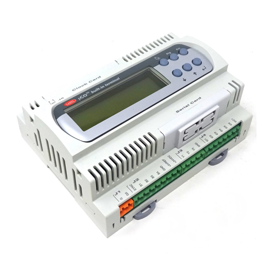
Page 20: Connections
Carel srl: pCO Stage Controller CONNECTIONS For an exhaustive description of the hardware and of the installation procedure please refer to the "User manual" of the pCO, available on request. Hardware architecture Fig. 17 The hardware architecture is as follows: 1. -
Page 21: Main Board - Layout
Carel srl: pCO Stage Controller Main board - layout Fig. 18 The main board (code PCOB000***) is the basic core of the controller and includes 4 different areas: • microprocessor and memories of the unit • terminal blocks necessary to interface the pCO to the controlled devices •... - Page 22 J9 in position 1-2 enables the supervisor to reset the pCO board, in position 2-3 makes the pCO board independent of the reset action of the supervisor The interface pCO boards by Carel have both jumpers in position 1-2 Caution: in this EPROM not exists the local network” management 8.
-
Page 23: Meaning Of The Inputs And Outputs
Carel srl: pCO Stage Controller MEANING OF THE INPUTS AND OUTPUTS Power supply ONNECTOR IGNAL ESCRIPTION J17 - 1 Power supply + 24 V 10 W or 24V~50/60 Hz 15 VA (see note on page 25) J17 - 2 Power supply reference... - Page 24 Carel srl: pCO Stage Controller Digital outputs ONNECTOR IGNAL ESCRIPTION J22 - 1 NO11 General alarm - contact normally open J22 - 2 Common general alarm J22 - 3 NC11 General alarm - contact normally closed J22 - 4 Not connected...
-
Page 25: Connection Of The Inputs
Fig. 30 pressure switch / antifreeze (see Analog inputs • from B1 to B4 for probes NTC Carel • B5 and B6 for active-voltage probes (0÷1V ) or current probes (4÷20 mA) selectable by jumper Types of probes that can be connected to the analog inputs... -
Page 26: Connection Of The Outputs
Carel srl: pCO Stage Controller As previously mentioned the analog inputs B5 and B6 can receive either probes with voltage output signals (-1÷1 ) or probes with current output signals (4÷20mA). 4 - 20 mA -1 / 1 Volt (factory set) Fig. -
Page 27: Connection Between Terminal Unit And Main Board
To unplug the connector, push gently the prominent plastic tab and remove the cable. Carel serial connection have three different lengths: S90CONN002: length 0.8 m S90CONN000: length 1.5 m Terminal unit S90CONN001: length 3 m The main board can operate also in the absence of the terminal unit;... -
Page 28: Connection Of The Optional Boards
Carel srl: pCO Stage Controller CONNECTION OF THE OPTIONAL BOARDS Serial printer It is possible to use the serial printer only if the pCO terminal with the following code is available: PC0T00SL60 terminal unit with 6-digit LED display. This terminal unit is equipped with a dedicated 9-pole male connector Fig. -
Page 29: Useful Advice For A Correct Installation
Carel srl: pCO Stage Controller USEFUL ADVICE FOR A CORRECT INSTALLATION Do not mount the boards in places with the following features: • Wide and quick ambient temperature variations • Relative humidity higher than 85% • Strong vibrations and shocks •... -
Page 30: Appendix A: Troubleshooting
Carel srl: pCO Stage Controller APPENDIX A: TROUBLESHOOTING The unit does not start (the mains presence LED on the main board is off, the LCD is off, the other LEDs are off). Check: a) the mains; b) that after the 230V~ - 240V~ power transformer there are 24V~;... - Page 31 (not supplied by Carel, see note on page 25); c) the metallic mounting hardware must be used when mounting the main card to the electrical panel.
-
Page 32: Appendix B: Connections
Carel srl: pCO Stage Controller APPENDIX B: CONNECTIONS Connection of the pCO to the other devices. 230V~ / 24V~ 24V~ / 24V~ G ener alal ar m ( gener alhi gh pr ess ur e s wi t ch) Sel ect i on set poi ntby pot ent i om et er or... -
Page 33: Appendix C: Examples Of Appliances
Carel srl: pCO Stage Controller APPENDIX C: EXAMPLES OF APPLIANCES This versatile instrument can be differently programmed according to the characteristics of the plant to be managed. For this reason here the connection diagrams of some appliances are shown. Refrigerator unit consisting of: •... - Page 34 Carel srl: pCO Stage Controller Refrigerator unit consisting of: • • 3 compressors 2 pressure probes • fans inverter POWER SUPPLY ANALOG OUTPUS 24V~ FINV ANALOG INPUTS AVSS AVSS AVSS +24V DIGITAL OUTPUTS NO11 NO10 NO12 CMP3 CMP2 CMP1 DIGITAL INPUTS...
- Page 35 Carel srl: pCO Stage Controller Chiller unit consisting of: • • 5 Compressors 2 NTC temperature probes • • 1 Stage of voltage control for comp. 1 External air temperature probe • (compensation) remote On/Off from analog input POWER SUPPLY...
-
Page 36: Appendix D: Materials And Codes
PCOB000B21 Terminal pCO 6 digit LED PCOT01SL60 Telephone connector 1.5m long S90CONN000 Clock board CLK0000000 EPROM with programme EPSTDIIU0A Optional : Serial board PCOSER0000 Serial board PCOSER4850 Carel reserves the right to modify its products without prior notice. page 35...
Need help?
Do you have a question about the pCO Series and is the answer not in the manual?
Questions and answers