
Related Manuals for Penguin Computing Relion 1900e


Summary of Contents for Penguin Computing Relion 1900e
- Page 1 Relion 1900e Technical Guide Rev. 1.0 PENGUIN COMPUTING www.penguincomputing.com | 1-888-PENGUIN (736-4846) | twitter:@PenguinHPC...
- Page 2 Relion 1900e/2900e Manual Revision 1.3 April 2016 Intel Server Boards and Systems ®...
-
Page 3: Revision History
Relion 1900e/2900e Manual Revision History Date Revision Modifications Number August 2014 1..0 External Public Release Changes from previous release: December 2014 1.01 • Removed content references to PCIx Riser Card support Added Appendix F – Statement of Volatility • Changes from previous release: •... - Page 4 Penguin Computing reserves these for future definition and shall have no responsibility whatsoever for conflicts or incompatibilities arising from future changes to them. The Relion 1900e/2900e may contain design defects or errors known as errata which may cause the product to deviate from published specifications. Current characterized errata are available on request.
-
Page 5: Table Of Contents
Relion 1900e/2900e Manual Table of Contents 1. Introduction ............................1 Chapter Outline ............................ 1 Server Board Use Disclaimer ......................1 2. Product Features Overview ......................2 Server Board Component/Feature Identification ..............4 Product Architecture Overview ..................... 8 System Software Overview ......................9 2.3.1... - Page 6 Relion 1900e/2900e Manual PCIe* Support ............................ 32 PCIe* Enumeration and Allocation ................... 33 PCIe* Non-Transparent Bridge (NTB) ..................33 Add-in Card Support ........................34 5.4.1 Riser Card Support .......................... 35 5.4.2 Intel® I/O Module Support ......................38 5.4.3 Intel Integrated RAID Option ...................... 39 ®...
- Page 7 Relion 1900e/2900e Manual 7.2.2 Advanced Configuration and Power Interface (ACPI) ............61 7.2.3 System Initialization ........................61 7.2.4 Watchdog Timer ..........................62 7.2.5 System Event Log (SEL) ......................... 62 Sensor Monitoring ........................... 62 7.3.1 Sensor Scanning ..........................63 7.3.2 Sensor Rearm Behavior ......................... 63 7.3.3...
- Page 8 Relion 1900e/2900e Manual 9.3.1 Keyboard, Video, Mouse (KVM) Redirection ................. 87 9.3.2 Remote Console ..........................88 9.3.3 Performance ............................88 9.3.4 Security ..............................89 9.3.5 Availability ............................89 9.3.6 Usage ..............................89 9.3.7 Force-enter BIOS Setup ........................ 89 9.3.8 Media Redirection ..........................89 10.
- Page 9 Relion 1900e/2900e Manual 11.6 BIOS Recovery Jumper ....................... 106 12. Light Guided Diagnostics ......................107 12.1 System ID LED ..........................108 12.2 System Status LED ........................108 12.3 BMC Boot/Reset Status LED Indicators ................111 12.4 Post Code Diagnostic LEDs ....................... 111 12.5...
- Page 10 Light Guided Diagnostic LED Identification ................6 ® Figure 5. Jumper Block Identification ........................7 Figure 6. Relion 1900e/2900e Architectural Block Diagram ............. 8 Figure 7. Processor Socket Assembly ....................... 14 Figure 8. LGA2011-3 ILM (Narrow) ........................14 Figure 9. Memory Sub-system Block Diagram ....................21 Figure 10.
- Page 11 Relion 1900e/2900e Manual Figure 36. Relion 1900e....................149 Figure 37. Relion 2900e ....................152 Revision 1.3...
- Page 12 Table 3. Mixed Processor Configurations Error Summary ................. 16 Table 4. DDR4 RDIMM & LRDIMM Support ..................... 23 Table 5. Relion 1900e/2900e Memory Slot Identification ..............25 Table 6. DIMM Population Matrix ......................... 26 Table 7. PCIe* Port Routing CPU #1 ........................32 Table 8.
- Page 13 Table 64. POST Error Codes and Messages....................141 Table 65. POST Error Beep Codes ........................146 Table 66. Integrated BMC Beep Codes ......................146 Table 67. Relion 1900e Feature Set ....................149 Table 68. Relion 2900e Feature Set ....................152 Revision 1.3...
- Page 14 Relion 1900e/2900e Manual <This page is intentionally left blank.> Revision 1.3 xiii...
-
Page 16: Introduction
External Product Specifications (EPS) or External Design Specifications (EDS) related to this server generation. EPS and EDS documents are made available under NDA with Penguin Computing and must be ordered through your local Penguin Computing representative. See the Reference Documents section for a list of available documents. -
Page 17: Product Features Overview
• Intel ® Ethernet Controller I350, supporting 1 GbE (Intel Server Board Product Code – S2600WT2R) All other onboard features will be identical. Table 1. Relion 1900e/2900e Feature Set Feature Description • Two LGA2011-3 (Socket R3) processor sockets Processor Support •... - Page 18 Relion 1900e/2900e Manual Feature Description Server board includes three PCIe* 3.0 compatible riser card only slots: • Riser #1 – PCIe* 3.0 x24 – up to 3 PCIe* slots in 2U Riser #2 – PCIe* 3.0 x24 – up to 3 PCIe* slots in 2U 2U Server –...
-
Page 19: Server Board Component/Feature Identification
Relion 1900e/2900e Manual Server Board Component/Feature Identification The following illustration provides a general overview of the server board, identifying key feature and component locations. Figure 1. Server Board Component/Features Identification Revision 1.0... -
Page 20: Figure 2. Sw2600T External I/O Connector Layout
Relion 1900e/2900e Manual The back edge of the server board includes several external connectors to support the following features: A – RJ45 Networking Port – NIC #1 B – RJ45 Networking Port – NIC #2 C – Video D – RJ45 Serial ‘A’ Port E –... -
Page 21: Figure 4. Intel Light Guided Diagnostic Led Identification
Relion 1900e/2900e Manual Figure 4. Intel Light Guided Diagnostic LED Identification ® Note: See Appendix D for POST Code Diagnostic LED decoder information Revision 1.0... -
Page 22: Figure 5. Jumper Block Identification
Relion 1900e/2900e Manual Figure 5. Jumper Block Identification See Chapter 11 - Reset & Recovery Jumpers for additional details. Revision 1.3... -
Page 23: Product Architecture Overview
Relion 1900e/2900e Manual Product Architecture Overview The architecture of Relion 1900e/2900e is developed around the integrated features and functions of the Intel ® Xeon ® processor E5-2600 v3, v4 product family, the Intel ® C612 chipset, Intel ® Ethernet Controllers I350 1 GbE or X540 10 GbE, and the Emulex* Pilot-III Baseboard Management Controller. -
Page 24: System Software Overview
Relion 1900e/2900e Manual System Software Overview The server board includes an embedded software stack to enable, configure, and support various system functions. This software stack includes the System BIOS, Baseboard Management Controller (BMC) Firmware, Management Engine (ME) Firmware, and management support data including Field Replaceable Unit (FRU) data, and Sensor Data Record (SDR) data. - Page 25 Relion 1900e/2900e Manual 2.3.1.1 BIOS Revision Identification The BIOS Identification string is used to uniquely identify the revision of the BIOS being used on the server. The BIOS ID string is displayed on the Power-On Self -Test (POST) Diagnostic Screen and in the <F2> BIOS Setup Main Screen, as well as in System Management BIOS (SMBIOS) structures.
-
Page 26: Table 2. Post Hot-Keys
Relion 1900e/2900e Manual 2.3.1.2 Hot Keys Supported During POST Certain “Hot Keys” are recognized during POST. A Hot Key is a key or key combination that is recognized as an unprompted command input, that is, the operator is not prompted to press the Hot Key and typically the Hot Key will be recognized even while other processing is in progress. - Page 27 Relion 1900e/2900e Manual 2.3.1.5 Entering BIOS Setup To enter the BIOS Setup Utility using a keyboard (or emulated keyboard), press the <F2> function key during boot time when the OEM or Intel Logo Screen or the POST Diagnostic Screen is displayed.
-
Page 28: Field Replaceable Unit (Fru) And Sensor Data Record (Sdr) Data
Relion 1900e/2900e Manual Once the update has completed, the recovery jumper is switched back to its default position and the system is power cycled. If the BIOS detects a partial BIOS update or the BMC asserts Recovery Mode GPIO, the BIOS will boot up with Recovery Mode. -
Page 29: Processor Support
Relion 1900e/2900e Manual Processor Support The server board includes two Socket-R3 (LGA2011-3) processor sockets and can support one or two of the following processors: Intel ® Xeon ® processor E5-2600 v3, v4 product family Supported Thermal Design Power (TDP) of up to 145W. -
Page 30: Processor Thermal Design Power (Tdp) Support
2600 v3, v4 product family TDP guidelines up to and including 145W. Disclaimer Note: Penguin Computing server boards contain a number of high-density VAVAGO and power delivery components that need adequate airflow to cool. Penguin ensures through its own chassis development and testing that when Penguin server building blocks are used together, the fully integrated system will meet the intended thermal requirements of these components. -
Page 31: Processor Initialization Error Summary
Relion 1900e/2900e Manual Processor Initialization Error Summary The following table describes mixed processor conditions and recommended actions for all Intel ® server boards and Intel server systems designed around the Intel ® Xeon ® processor E5-2600 v3, v4 product family and Intel ®... - Page 32 Relion 1900e/2900e Manual Error Severity System Action The BIOS detects the error condition and responds as follows: Halts at POST Code 0xE5. Processor cores/threads not Fatal Halts with 3 long beeps and 1 short beep. identical Takes Fatal Error action (see above) and will not boot until the fault condition is remedied.
-
Page 33: Processor Function Overview
Relion 1900e/2900e Manual Error Severity System Action The BIOS detects the error condition and responds as follows: Logs the POST Error Code into the SEL. Processor microcode update Displays “818x: Processor 0x microcode update not found” message in the Error... - Page 34 Relion 1900e/2900e Manual 3.5.2.1 Intel ® Virtualization Technology (Intel ® VT) for Intel ® 64 and IA-32 Intel ® Architecture (Intel ® VT-x) Hardware support in the core, to improve performance and robustness for virtualization. Intel VT-x specifications and functional descriptions are included in the Intel® 64 and IA-32 Architectures Software Developer’s Manual.
- Page 35 Relion 1900e/2900e Manual Enhanced Intel SpeedStep Technology builds upon that architecture using design strategies that include the following: Separation between Voltage and Frequency changes. By stepping voltage up and down in small increments separately from frequency changes, the processor is able to reduce periods of system unavailability (which occur during frequency change).
-
Page 36: System Memory
Relion 1900e/2900e Manual System Memory This chapter describes the architecture that drives the memory sub-system, supported memory types, memory population rules, and supported memory RAS features. Memory Sub-system Architecture CPU-1 CPU-2 DDR4 – CH0 CH0 – DDR4 ® ® ®... -
Page 37: Imc Modes Of Operation
Relion 1900e/2900e Manual IMC Modes of operation A memory controller can be configured to operate in one of two modes, and each IMC operates separately. Independent Mode: This is also known as performance mode. In this mode each DDR channel is addressed individually via burst lengths of 8 bytes. -
Page 38: Supported Memory
Relion 1900e/2900e Manual DDR4 Command/Address Parity Check and Retry: DDR4 technology based CMD/ADDR parity check and retry with following attributes: CMD/ADDR Parity error address logging CMD/ADDR Retry Intra-Socket Memory Mirroring: Memory Mirroring is a method of keeping a duplicate (secondary or mirrored) copy of the contents of memory as a redundant backup for use if the primary memory fails. -
Page 39: Nvdimm Support
Relion 1900e/2900e Manual NVDIMM Support Future enhancement Memory Slot Identification and Population Rules Note: Although mixed DIMM configurations may be functional, Intel only supports and performs platform validation on systems that are configured with identical DIMMs installed. Each installed processor provides four channels of memory. On the S2600WT each ... -
Page 40: Figure 11. S2600Wt Memory Slot Layout
Relion 1900e/2900e Manual On the S2600WT a total of 24 DIMM slots is provided – 2 CPUs, 4 Memory Channels/CPU, 3 DIMMs/Channel. The nomenclature for memory slots is detailed in the following table: Table 5. S2600WT Memory Slot Identification Processor Socket 1... -
Page 41: Table 6. Dimm Population Matrix
Relion 1900e/2900e Manual LRDIMM Rank Multiplication Mode and Direct Map Mode must not be mixed within or across processor sockets. This is a Fatal Error Halt in Memory Initialization. In order to install 3 QR LRDIMMs on the same channel, they must be operated with Rank ... -
Page 42: Memory Interleaving Support
Relion 1900e/2900e Manual Processor Socket 1 = Populated Processor Socket 2 = Populated # of DIMMs M – Indicates whether the configuration supports the Mirrored Channel Mode of operation. 4.6.1 Memory Interleaving Support The Intel® Xeon® Processor E5-4600/2600/2400/1600 v3, v4 a Product Families support multiple levels of memory interleaving. -
Page 43: Publishing System Memory
Relion 1900e/2900e Manual Independent Channel mode: In Independent Channel Mode, the amount of installed physical memory is the amount of effective memory available. There is no reduction. Lockstep Mode: For Lockstep Mode, the amount of installed physical memory is the amount of ... -
Page 44: Memory Initialization
Relion 1900e/2900e Manual Memory Mapped I/O (MMIO) Manageability Engine (ME) BIOS flash Memory Initialization Memory Initialization at the beginning of POST includes multiple functions, including: DIMM discovery Channel training DIMM population validation check Memory controller initialization and other hardware settings ... -
Page 45: Channel Training
Relion 1900e/2900e Manual Potential Error Cases: Invalid DIMM (type, organization, speed, size) – If a DIMM is found that is not a type supported by the system, the following error will be generated: POST Error Code 8501 “DIMM Population Error”, and a “Population Error- Fatal Error Halt 0xED”. - Page 46 Relion 1900e/2900e Manual installed on the channel behind the failed DIMM will be marked as disabled, with POST Error Code 854x “DIMM Disabled”. This results in a momentary Error Display 0xEB, and if all DIMMs have failed, this will result in a Fatal Error Halt 0xE8.
-
Page 47: System I/O
Ethernet controller I350 or X540, and the I/O controllers embedded within the Emulex* Pilot-III Management Controller. See Figure 6. Relion 1900e/2900e Architectural Block Diagram for an overview of the features and interconnects of each of the major sub-system components PCIe* Support The processor side PCI Express interface of S2600 server boards is fully compliant with the PCI Express Base Specification, Revision 3.0. -
Page 48: Pcie* Enumeration And Allocation
Relion 1900e/2900e Manual Port 3C - x4 Riser Slot #1 Port 3D -x4 Riser Slot #1 Table 8. PCIe* Port Routing – CPU #2 CPU 2 PCI Ports Device (D) Function (F) On-board Device Port DMI 2/PCIe* x4 0 Riser Slot #3... -
Page 49: Add-In Card Support
Relion 1900e/2900e Manual host memory domain from the remote host memory domain while enabling status and data exchange between the two domains. The PCI express* Port 3A of Intel® Xeon® Processor E5-2600 v3, v4 Product Families can be configured to be a transparent bridge or an NTB with x4/x8/x16 link width and Gen1/Gen2/Gen3 link speed. -
Page 50: Riser Card Support
Relion 1900e/2900e Manual Figure 12. On-board Add-in Card Support 5.4.1 Riser Card Support The server board provides three riser card slots identified as: Riser Slot #1, Riser Slot #2, and Riser Slot #3. Note: The riser card slots are specifically designed to support riser cards only. Attempting to install a PCIe* add-in card directly into a riser card slot on the server board may damage the server board, the add-in card, or both. -
Page 51: Figure 13. 1U One Slot Pcie* Riser Card (Ipc - F1Ul16Riser2)
Relion 1900e/2900e Manual Table 11. Riser Slot #3 - PCIe* Root Port Mapping Riser Slot #3 - Riser Card Options 2U - Low Profile Riser Card Notes iPN – A2UX8X4RISER Top PCIe* Slot CPU #2 – Port DMI 2 PCIe* 2.0 Support Only... -
Page 52: Figure 15. 2U Two Pcie* Slot Riser Card (Ipc - A2Ul16Riser2)
Relion 1900e/2900e Manual Each riser card assembly has support for up to two full height full length add-in cards (top and middle slots) and one full height ½ length add-in card (bottom slot). 2U – Two PCIe* add-in card slots ... -
Page 53: Intel® I/O Module Support
Relion 1900e/2900e Manual 5.4.2 Intel® I/O Module Support To broaden the standard on-board feature set, the server board provides support for one of several available Intel® I/O Module options. The I/O module attaches to a high density 80-pin connector on the server board labeled “IO_Module”... -
Page 54: Intel Integrated Raid Option
Relion 1900e/2900e Manual 5.4.3 Intel ® Integrated RAID Option The server board provides support for Intel Integrated RAID modules. These optional modules attach to a ® high density 80-pin connector labeled “SAS Module” on the server board and are supported by x8 PCIe* 3.0 signals from the IIO module of the CPU 1 processor. -
Page 55: Serial Ata (Sata) Support
Relion 1900e/2900e Manual Serial ATA (SATA) Support The server board utilizes two chipset embedded AHCI SATA controllers, identified as SATA and sSATA, providing for up to ten 6 Gb/sec Serial ATA (SATA) ports. The AHCI SATA controller provides support for up to six SATA ports on the server board Four SATA ports from the Mini-SAS HD (SFF-8643) connector labeled “SATA Ports 0-3”... -
Page 56: Table 13. Sata And Ssata Controller Bios Utility Setup Options
Relion 1900e/2900e Manual Table 13. SATA and sSATA Controller BIOS Utility Setup Options sSATA Controller Supported SATA Controller AHCI AHCI AHCI Enhanced AHCI Disabled AHCI RSTe AHCI ESRT2 Microsoft* Windows Only Enhanced AHCI Enhanced Enhanced Enhanced Disabled Enhanced RSTe Enhanced... -
Page 57: Staggered Disk Spin-Up
Relion 1900e/2900e Manual AHCI / RAID AHCI / RAID Feature Description Disabled Enabled Reduces interrupt and completion overhead by allowing a specified number of commands to Command Completion Coalescing Supported complete and then generating an interrupt to process the commands 5.5.1... -
Page 58: Intel
Relion 1900e/2900e Manual rate. RAID 5 is well suited for applications that require high amounts of storage while maintaining fault tolerance. Note: RAID configurations cannot span across the two embedded AHCI SATA controllers. By using Intel ® RSTe, there is no loss of PCI resources (request/grant pair) or add-in card slot. Intel ®... -
Page 59: Network Interface
Relion 1900e/2900e Manual Figure 20. SATA RAID 5 Upgrade Key Maximum drive support = 6 (Maximum on-board SATA port support) Open Source Compliance = Binary Driver (includes Partial Source files) or Open Source using MDRAID layer in Linux*. -
Page 60: Intel® Ethernet Controller Options
Relion 1900e/2900e Manual Color LED State NIC State LAN link not established Left Green LAN link is established Blinking Transmit / Receive Activity Lowest supported data rate Right Amber Mid-range supported data rate Green Highest supported data rate Figure 22. External RJ45 NIC Port LED Definition NOTE: Lowest, Mid-range, and Highest supported data rate is dependent on which onboard networking controller option is present. -
Page 61: Dual Video And Add-In Video Adapters
Relion 1900e/2900e Manual The integrated video controller supports all standard IBM* VGA modes. The following table shows the 2D modes supported for both CRT and LCD: Table 15. Video Modes 2D Mode 2D Video Mode Support 640x480 800x600 1024x768 1152x864... - Page 62 Relion 1900e/2900e Manual 5.8.1.1 Dual Monitor Video The BIOS supports single and dual video on the S2600 family of Server Board when add-in video adapters are installed. Although there is no enable/disable option in BIOS screen for Dual Video, it works when both “Onboard video”...
-
Page 63: Setting Video Configuration Options Using The Bios Setup Utility
Relion 1900e/2900e Manual Legacy VGA Socket = CPU Socket 1 Add-in Video Adapter = Disabled Case 8: Add-in video on Socket 1 active display, onboard video and Add-in video on Socket 2 don’t actively display. Onboard Video = Disabled Legacy VGA Socket = CPU Socket 1 Add-in Video Adapter = Enabled Case 9: Both onboard video active and CPU Socket 1 add-in video active display. - Page 64 Relion 1900e/2900e Manual If there is no add-in video card in any PCIe* slot connected to CPU Socket 1 with the Legacy VGA Socket option set to CPU Socket 1, this option is set to Disabled and grayed out and unavailable.
-
Page 65: Usb Support
Relion 1900e/2900e Manual USB Support The server board provides support for both USB 2.0 (up to 480 Mb/sec) and USB 3.0 (up to 5 Gb/sec). ® Intel C612 Integrated USB 2.0 (4,12) Chipset USB 2.0 & USB 3.0 I/O Internal Mount... -
Page 66: Serial Ports
Relion 1900e/2900e Manual eUSB SSD features include: 2 wire small form factor Universal Serial Bus 2.0 (Hi-Speed USB) interface to host • Read Speed up to 35 MB/s and write Speed up to 24 MB/s. • Capacity range from 256 MB to 32 GB. -
Page 67: Table 17. Serial-B Connector Pin-Out
Relion 1900e/2900e Manual ** Pin 7 of the RJ45 Serial A connector is configurable to support either a DSR (Default) signal or a DCD signal. Pin 7 signals are changed by moving the jumper on the jumper block labeled “J4A4”, located behind the connector, from pins 1-2 (default) to pins 2-3. -
Page 68: System Security
Relion 1900e/2900e Manual System Security The server board supports a variety of system security options designed to prevent unauthorized system access or tampering of server settings. System security options supported include: Password Protection • Front Panel Lockout • Trusted Platform Module (TPM) support •... -
Page 69: System Administrator Password Rights
Relion 1900e/2900e Manual The Administrator and User passwords must be different from each other. An error message will be displayed and a different password must be entered if there is an attempt to enter the same password for both. The use of “Strong Passwords” is encouraged, but not required. In order to meet the criteria for a strong password, the password entered must be at least 8 characters in length, and must include at least one each of alphabetic, numeric, and special characters. -
Page 70: Front Panel Lockout
Relion 1900e/2900e Manual 6.1.4 Front Panel Lockout If enabled in BIOS setup, this option disables the following front panel features: • The OFF function of the Power button • System Reset button • NMI Diagnostic Interrupt button If [Enabled] is selected, system power off and reset must be controlled via a system management interface. -
Page 71: Tpm Security Bios
Relion 1900e/2900e Manual 6.2.1 TPM security BIOS The BIOS TPM support conforms to the TPM PC Client Implementation Specification for Conventional BIOS, the TPM Interface Specification, and the Microsoft Windows BitLocker* Requirements. The role of the BIOS for TPM security includes the following: Measures and stores the boot process in the TPM microcontroller to allow a TPM enabled operating ... -
Page 72: Intel Trusted Execution Technology
Relion 1900e/2900e Manual Setup Options using the BIOS Setup Utility Table 18. TPM Setup Utility – Security Configuration Screen Fields Setup Item Options Help Text Comments TPM State Enabled and Activated Information only. Enabled and Deactivated Shows the current TPM device state. -
Page 73: Platform Management
Relion 1900e/2900e Manual When available, Intel Trusted Execution Technology can be enabled or disabled in the processor from a BIOS Setup option. Platform Management Platform management is supported by several hardware and software components integrated on the server board that work together to support the following: Control systems functions –... -
Page 74: Non Ipmi Features Overview
Relion 1900e/2900e Manual o LAN interface that supports the IPMI-over-LAN protocol (RMCP, RMCP+) Serial-over-LAN (SOL) ACPI state synchronization: The BMC tracks ACPI state changes that are provided by the BIOS. BMC self-test: The BMC performs initialization and run-time self-tests and makes results available to ... - Page 75 Relion 1900e/2900e Manual Integrated KVM (with Intel® RMM4 Lite option installed) Enhancements to KVM redirection (with Intel® RMM4 Lite option installed) o Support for higher resolution Integrated Remote Media Redirection Lightweight Directory Access Protocol (LDAP) support ...
-
Page 76: Platform Management Features And Functions
Relion 1900e/2900e Manual Platform Management Features and Functions 7.2.1 Power Sub-system The server board supports several power control sources which can initiate power-up or power-down activity. Table 19. Server Board Power Control Sources External Signal Name or Source Capabilities Internal Subsystem... -
Page 77: Watchdog Timer
Relion 1900e/2900e Manual 7.2.3.2 Fault Resilient Booting (FRB) Fault resilient booting (FRB) is a set of BIOS and BMC algorithms and hardware support that allow a multiprocessor system to boot even if the bootstrap processor (BSP) fails. Only FRB2 is supported using watchdog timer commands. -
Page 78: Sensor Scanning
Relion 1900e/2900e Manual system state changes by maintaining virtual sensors that are not specifically tied to physical hardware. This section describes general aspects of BMC sensor management as well as describing how specific sensor types are modeled. Unless otherwise specified, the term “sensor” refers to the IPMI sensor-model definition of a sensor. -
Page 79: Bios Event-Only Sensors
Relion 1900e/2900e Manual All auto-rearm sensors that show an asserted event status generate a de-assertion SEL event at the time the BMC detects that the condition causing the original assertion is no longer present; and the associated SDR is configured to enable a de-assertion event for that condition. -
Page 80: Thermal Monitoring
Relion 1900e/2900e Manual 7.3.10 Thermal Monitoring The BMC provides monitoring of component and board temperature sensing devices. This monitoring capability is instantiated in the form of IPMI analog/threshold or discrete sensors, depending on the nature of the measurement. For analog/threshold sensors, with the exception of Processor Temperature sensors, critical and non-critical thresholds (upper and lower) are set through SDRs and event generation enabled for both assertion and de- assertion events. - Page 81 Relion 1900e/2900e Manual The BMC supports one IPMI processor (margin) temperature sensor per physical processor package. This sensor aggregates the readings of the individual core temperatures in a package to provide the hottest core temperature reading. When the sensor reads ‘0’, it indicates that the hottest processor core is throttling.
- Page 82 Relion 1900e/2900e Manual 7.3.10.8 Server South Bridge (SSB) Thermal Monitoring The BMC monitors the SSB temperature. This is instantiated as an analog (threshold) IPMI thermal sensor. 7.3.10.9 Exit Air Temperature Monitoring This sensor is only available on systems in an Intel ®...
-
Page 83: Processor Sensors
Relion 1900e/2900e Manual This is a manual re-arm sensor that is rearmed on system resets and power-on (AC or DC power on transitions). 7.3.11 Processor Sensors The BMC provides IPMI sensors for processors and associated components, such as voltage regulators and fans. - Page 84 Relion 1900e/2900e Manual At BMC startup, the BMC will check for the fault condition and set the sensor state accordingly. The BMC also checks for this fault condition at each attempt to DC power-on the system. At each DC power-on attempt, a beep code is generated if this fault is detected.
-
Page 85: Voltage Monitoring
Relion 1900e/2900e Manual ED1 – 0xA1 ED2 - CATERR type. 0: Unknown 1: CATERR 2: CPU Core Error (not supported on Intel ® Server Systems supporting the Intel ® Xeon ® processor E5-2600 v3, v4product family) 3: MSID Mismatch 4: CATERR due to CPU 3-strike timeout ED3 - CPU bitmap that causes the system CATERR. - Page 86 Relion 1900e/2900e Manual As a result, fan tach sensors do not auto-rearm when the fault condition goes away but rather are rearmed for either of the following occurrences: a. The system is reset or power-cycled. b. The fan is removed and either replaced with another fan or re-inserted. This applies to hot- swappable fans only.
-
Page 87: Standard Fan Management
Relion 1900e/2900e Manual the BMC FW to halt updates to the value of the associated fan tach sensor and set that sensor’s IPMI sensor state to “reading-state-unavailable” when this mode is active. Management software must comprehend this state for fan tach sensors and not report these as failure conditions. - Page 88 Relion 1900e/2900e Manual When a fan is not present, the associated fan speed sensor is put into the reading/unavailable state, and any associated fan domains are put into the boost state. The fans may already be boosted due to a previous fan failure or fan removal.
- Page 89 Relion 1900e/2900e Manual Multiple stepwise linear and clamp controls can be defined for each fan domain and used simultaneously. For each domain, the BMC uses the maximum of the domain’s stepwise linear control contributions and the sum of the domain’s clamp control contributions to compute the domain’s PWM value, except that a stepwise linear instance can be configured to provide the domain maximum.
-
Page 90: Figure 26. High-Level Fan Speed Control Process
Relion 1900e/2900e Manual On-board sensor Virtual sensor Available only when PSU has PMBus Calculated estimate A simple model is shown in the following figure which gives a high level representation of how the fan speed control structure creates the resulting fan speeds. - Page 91 Relion 1900e/2900e Manual have valid temp sensors and some do not) is not supported. The BMC fan speed control functionality is related to the memory throttling mechanism used. The following terminology is used for the various memory throttling options: •...
- Page 92 Relion 1900e/2900e Manual BIOS and BMC will handshake to automatically understand configuration details and automatically select the optimal fan speed control profile in the BMC. Customers will only select a performance or an acoustic profile selection from the BIOS menu for EPSD system and the fan speed control will be optimal for the configuration loaded.
-
Page 93: Power Management Bus (Pmbus*)
Relion 1900e/2900e Manual adapter is configured into the system. This enables easier usage of the fan speed control to support Intel as well as third party chassis and better support of ambient temperatures higher than 35°C. 7.3.15 Power Management Bus (PMBus*) The Power Management Bus (“PMBus*”) is an open standard protocol that is built upon the SMBus* 2.0... -
Page 94: Nmi (Diagnostic Interrupt) Sensor
Relion 1900e/2900e Manual Component Owner Color State Description Fan failed Amber Solid On Fan Fault LED Amber Fan working correctly Amber Solid On Memory failure – detected by BIOS DIMM Fault LED Amber DIMM working correctly Amber HDD Fault HSBP... -
Page 95: Cmos Battery Monitoring
Relion 1900e/2900e Manual 7.3.21 CMOS Battery Monitoring The BMC monitors the voltage level from the CMOS battery, which provides battery backup to the chipset Real Time Clock. This is monitored as an auto-rearm threshold sensor. Unlike monitoring of other voltage sources for which the Emulex* Pilot III component continuously cycles through each input, the voltage channel used for the battery monitoring provides a SW enable bit to allow the BMC FW to poll the battery voltage at a relatively slow rate in order to conserve battery power. -
Page 96: Intel® Intelligent Power Node Manager (Nm) Support Overview
Relion 1900e/2900e Manual Intel® Intelligent Power Node Manager (NM) Support Overview Power management deals with requirements to manage processor power consumption and manage power at the platform level to meet critical business needs. Node Manager (NM) is a platform resident technology that enforces power capping and thermal-triggered power capping policies for the platform. -
Page 97: Peci 3.0
Relion 1900e/2900e Manual The ME uses the SMLink1 on the SSB in multi-master mode bus for communication with PMBus* devices in the power supplies for support of various NM-related features. This bus is shared with the BMC, which polls these PMBus* power supplies for sensor monitoring purposes (for example, power supply status, input power, and so on). -
Page 98: Dependencies On Pmbus*-Compliant Power Supply Support
Relion 1900e/2900e Manual 8.6.1 Dependencies on PMBus*-compliant Power Supply Support The SmaRT/CLST system feature depends on functionality present in the ME NM SKU. This feature requires power supplies that are compliant with the PMBus specification. Revision 1.3... -
Page 99: Basic And Advanced Server Management Features
Relion 1900e/2900e Manual Basic and Advanced Server Management Features The integrated BMC has support for basic and advanced server management features. Basic management features are available by default. Advanced management features are enabled with the addition of an optionally installed Remote Management Module 4 Lite (RMM4 Lite) key. -
Page 100: Dedicated Management Port
Relion 1900e/2900e Manual On the server board the Intel ® RMM4 Lite key is installed at the following location. RJ45 – Dedicated Management Port Intel ® RMM4 Lite Key Figure 27. Intel RMM4 Lite Activation Key Installation ® Dedicated Management Port The server board includes a dedicated 1GbE RJ45 Management Port. - Page 101 Relion 1900e/2900e Manual The GUI presented by the embedded web server authenticates the user before allowing a web session to be initiated. It presents all functions to all users but grays out those functions that the user does not have privilege to execute.
-
Page 102: Advanced Management Feature Support (Rmm4 Lite)
Relion 1900e/2900e Manual Server Power Control - Ability to force into Setup on a reset • System POST results – The web server provides the system’s Power-On Self Test (POST) • sequence for the previous two boot cycles, including timestamps. The timestamps may be displayed as a time relative to the start of POST or the previous POST code. -
Page 103: Remote Console
Relion 1900e/2900e Manual The KVM-redirection feature automatically senses video resolution for best possible screen capture and provides high-performance mouse tracking and synchronization. It allows remote viewing and configuration in pre-boot POST and BIOS setup, once BIOS has initialized video. Other attributes of this feature include: Encryption of the redirected screen, keyboard, and mouse ... -
Page 104: Security
Relion 1900e/2900e Manual 9.3.4 Security The KVM redirection feature supports multiple encryption algorithms, including RC4 and AES. The actual algorithm that is used is negotiated with the client based on the client’s capabilities. 9.3.5 Availability The remote KVM session is available even when the server is powered off (in stand-by mode). No restart of the remote KVM session shall be required during a server reset or power on/off. - Page 105 Relion 1900e/2900e Manual The mounted device is visible to (and usable by) managed system’s OS and BIOS in both pre-boot and post-boot states. The mounted device shows up in the BIOS boot order and it is possible to change the BIOS boot ...
-
Page 106: On-Board Connector/Header Overview
Relion 1900e/2900e Manual 10. On-board Connector/Header Overview This section identifies the location and pin-out for on-board connectors and headers of the server board that provide an interface to system options/features, on-board platform management, or other user accessible options/features. 10.1 Power Connectors The server board includes several power connectors that are used to provide DC power to various devices. -
Page 107: Hot Swap Backplane Power Connector
Relion 1900e/2900e Manual Table 27. Main Power (Slot 2) Connector Pin-out ("MAIN PWR 2”) Signal Name Pin # Pin# Signal Name GROUND GROUND GROUND GROUND GROUND GROUND GROUND GROUND GROUND GROUND GROUND GROUND GROUND GROUND GROUND GROUND GROUND GROUND P12V... -
Page 108: Peripheral Drive Power Connector
Relion 1900e/2900e Manual 10.1.3 Peripheral Drive Power Connector The server board includes one 6-pin power connector intended to provide power for peripheral devices such as Optical Disk Drives (ODD) and/or Solid State Devices (SSD). On the server board this connector is labeled as “Peripheral_ PWR”. -
Page 109: Front Panel Headers And Connectors
Relion 1900e/2900e Manual 10.2 Front Panel Headers and Connectors The server board includes several connectors that provide various possible front panel options. This section provides a functional description and pin-out for each connector. 10.2.1 Front Panel Button and LED Support Included near the right front edge of the server board are two front panel connectors: Standard 30-pin header “FRONT_PANEL”... -
Page 110: Front Panel Led And Control Button Features Overview
Relion 1900e/2900e Manual 10.2.2 Front Panel LED and Control Button Features Overview 10.2.2.1 Power/Sleep Button and LED Support Pressing the Power button will toggle the system power on and off. This button also functions as a sleep button if enabled by an ACPI compliant operating system. Pressing this button will send a signal to the integrated BMC, which will power on or power off the system. -
Page 111: Front Panel Usb 2.0 Connector
Relion 1900e/2900e Manual The following table describes behavior regarding NMI signal generation and event logging by the BMC. Table 34. NMI Signal Generation and Event Logging Signal Front Panel Diag Causal Event Generation Interrupt Sensor Event Logging Support Chassis Control command (pulse diagnostic –... -
Page 112: Front Panel Usb 3.0 Connector
Relion 1900e/2900e Manual 10.2.4 Front Panel USB 3.0 Connector The server board includes a Blue 20-pin connector that, when cabled, can provide up to two USB 2.0 / 3.0 ports to a front panel. On the server board the connector is labeled “FP_USB_2.0/3.0” and is located near the Main Power #1 connector. -
Page 113: On-Board Storage Option Connectors
Relion 1900e/2900e Manual Table 38. Intel Local Control Panel Connector Pin-out ("LCP") Signal Description Pin# SMB_SENSOR_3V3STBY_DATA_R0 GROUND SMB_SENSOR_3V3STBY_CLK P3V3_AUX FM_LCP_ENTER_N_R FM_LCP_LEFT_N_R FM_LCP_RIGHT_N_R 10.3 On-Board Storage Option Connectors The server board provides connectors to support several storage device options. This section provides a functional overview and pin-out of each connector. -
Page 114: Internal Type-A Usb Connector
Relion 1900e/2900e Manual Table 40. SATA SGPIO Connector Pin-out ("SATA_SGPIO") Signal Description Pin# SGPIO SATA CLK SGPIO SATA LOAD GROUND SGPIO SATA DATA OUT PU-SGPIO SATA 10.3.2 Internal Type-A USB Connector The server board includes one internal Type-A USB connector labeled “USB 2.0” and is located to the right of Riser Slot #1. -
Page 115: System Fan Connectors
Relion 1900e/2900e Manual 10.4 System Fan Connectors The server board is capable of supporting up to a total of six system fans. Each system fan includes a pair of fan connectors; a 1x10 pin connector to support a dual rotor cabled fan, typically used in 1U system configurations, and a 2x3 pin connector to support a single rotor hot swap fan assembly, typically used in 2U system configurations. -
Page 116: Other Connectors And Headers
Relion 1900e/2900e Manual 10.5 Other Connectors and Headers 10.5.1 Chassis Intrusion Header The server board includes a 2-pin chassis intrusion header which can be used when the chassis is configured with a chassis intrusion switch and the proper platform management SDR is programmed and installed. On the server board, this header is labeled “CHAS_INTR”... -
Page 117: Hot Swap Backplane I2C* Connectors
Relion 1900e/2900e Manual 10.5.4 Hot Swap Backplane I2C* Connectors The server board includes two 3-pin hot swap backplane I2C* connectors. These are located near the center of the board near the chipset heat sink, and towards the front left side of the board. Each is labeled as “HSBP I2C”. -
Page 118: Reset And Recovery Jumpers
Relion 1900e/2900e Manual 11. Reset and Recovery Jumpers The server board includes several jumper blocks which can be used to configure, protect, or recover specific features of the server board. The following diagram identifies the location of each jumper block on the server board. -
Page 119: Serial Port 'A' Configuration Jumper
Relion 1900e/2900e Manual 11.2 Serial Port ‘A’ Configuration Jumper See section 5.10 for details 11.3 Password Clear Jumper Block This jumper causes both the User password and the Administrator password to be cleared if they were set. The operator should be aware that this creates a security gap until passwords have been installed again through the <F2>... -
Page 120: Bmc Force Update Jumper Block
Relion 1900e/2900e Manual 9. Update the ME firmware using the following command: iflash32 /u /ni <version#>_ME.cap 10. When the update has successfully completed, power off the system 11. Remove the AC power cords 12. Remove the system top cover 13. Move the “ME FRC UPD” jumper back to pins 1-2 (default) 14. -
Page 121: Bios Recovery Jumper
Relion 1900e/2900e Manual 11.6 BIOS Recovery Jumper When the BIOS Recovery jumper block is moved from its default pin position (pins 1-2), the system will boot using a backup BIOS image to the uEFI shell, where a standard BIOS update can be performed. See the BIOS update instructions that are included with System Update Packages (SUP) downloaded from Intel’s... -
Page 122: Light Guided Diagnostics
Relion 1900e/2900e Manual 12. Light Guided Diagnostics The server board includes several on-board LED indicators to aid troubleshooting various board level faults. The following diagram shows the location for each LED. Figure 32. On-Board Diagnostic LED Placement Revision 1.3... -
Page 123: System Id Led
Relion 1900e/2900e Manual Figure 33. DIMM Fault LED Placement 12.1 System ID LED The server board includes a blue system ID LED which is used to visually identify a specific server installed among many other similar servers. There are two options available for illuminating the System ID LED. -
Page 124: Table 48. System Status Led State Definitions
Relion 1900e/2900e Manual Table 48. System Status LED State Definitions Color State Criticality Description System is Not ready System is powered off (AC and/or DC). • System is in EuP Lot6 Off Mode. • operating System is in S5 Soft-Off State. - Page 125 Relion 1900e/2900e Manual Color State Criticality Description Amber ~1 Hz Non-critical - Non-fatal alarm – system is likely to fail: blink System is • Critical threshold crossed – Voltage, temperature operating in a (including HSBP temp), input power to power supply,...
-
Page 126: Bmc Boot/Reset Status Led Indicators
Relion 1900e/2900e Manual 12.3 BMC Boot/Reset Status LED Indicators During the BMC boot or BMC reset process, the System Status LED and System ID LED are used to indicate BMC boot process transitions and states. A BMC boot will occur when AC power is first applied to the system. -
Page 127: Power Supply Specification Guidelines
Relion 1900e/2900e Manual 13. Power Supply Specification Guidelines This section provides power supply specification guidelines recommended for providing the specified server platform with stable operating power requirements. Note: The power supply data provided in this section is for reference purposes only. It reflects Intel’s own DC power out requirements for a 750W power supply as used in an Intel designed 2U server platform. -
Page 128: Power Supply Dc Output Specification
Relion 1900e/2900e Manual 13.2 Power Supply DC Output Specification 13.2.1 Output Power/Currents The following tables define the minimum power and current ratings. The power supply must meet both static and dynamic voltage regulation requirements for all conditions. Table 51. Minimum Load Ratings Parameter Max. -
Page 129: Capacitive Loading
Relion 1900e/2900e Manual 13.2.5 Capacitive Loading The power supply shall be stable and meet all requirements with the following capacitive loading ranges. Table 54. Capacitive Loading Conditions Output Units +12VSB 3100 µF +12V 25000 µF 13.2.6 Grounding The output ground of the pins of the power supply provides the output power return path. The output connector ground pins shall be connected to the safety ground (power supply enclosure). -
Page 130: Ripple/Noise
Relion 1900e/2900e Manual supplies must be able to load share in parallel and operate in a hot-swap/redundant 1+1 configurations. The 12VSBoutput is not required to actively share current between power supplies (passive sharing). The 12VSBoutput of the power supplies are connected together in the system so that a failure or hot swap of a redundant power supply does not cause these outputs to go out of regulation in the system. -
Page 131: Figure 34. Turn On/Off Timing (Power Supply Signals)
Relion 1900e/2900e Manual AC Input vout_holdup Vout pwok_low AC_on_delay pwok_off sb_on_delay sb_on_delay pwok_on pwok_off pwok_on PWOK pson_pwok pwok_holdup 12Vsb sb_vout 5Vsb holdup pson_on_delay PSON AC turn on/off cycle PSON turn on/off cycle Figure 34. Turn On/Off Timing (Power Supply Signals) -
Page 132: Appendix A - Integration And Usage Tips
Relion 1900e/2900e Manual Appendix A – Integration and Usage Tips When adding or removing components or peripherals from the server board, power cords must be disconnected from the server. With power applied to the server, standby voltages are still present even though the server board is powered off. -
Page 133: Appendix B - Integrated Bmc Sensor Tables
Relion 1900e/2900e Manual Appendix B – Integrated BMC Sensor Tables This appendix provides BMC core sensor information common to all Penguin server boards within this generation of product. Specific server boards and/or server platforms may only implement a sub-set of sensors and/or may include additional sensors. - Page 134 Relion 1900e/2900e Manual Rearm Sensors The rearm is a request for the event status for a sensor to be rechecked and updated upon a transition between good and bad states. Rearming the sensors can be done manually or automatically. This column indicates the type supported by the sensor. The following abbreviations...
-
Page 135: Table 57. Bmc Core Sensors
Relion 1900e/2900e Manual Note: All sensors listed below may not be present on all platforms. Please reference the BMC EPS for platform applicability. Redundancy sensors will only be present on systems with appropriate hardware to support redundancy (for instance, fan or power supply) Table 57. - Page 136 Relion 1900e/2900e Manual Full Sensor Name Sensor Platform Sensor Type Event/Rea Event Offset Triggers Contrib. To Assert Readabl Event Rearm Stand- Applicabil ding Type System Status /De- (Sensor name in SDR) Data assert Value/ Offsets 03 - Power cycle 08 - Timer interrupt...
- Page 137 Relion 1900e/2900e Manual Full Sensor Name Sensor Platform Sensor Type Event/Rea Event Offset Triggers Contrib. To Assert Readabl Event Rearm Stand- Applicabil ding Type System Status /De- (Sensor name in SDR) Data assert Value/ Offsets 03 - Non-redundant: Sufficient resources.
- Page 138 Relion 1900e/2900e Manual Full Sensor Name Sensor Platform Sensor Type Event/Rea Event Offset Triggers Contrib. To Assert Readabl Event Rearm Stand- Applicabil ding Type System Status /De- (Sensor name in SDR) Data assert Value/ Offsets Digital IO Module2 Presence Module/Board...
- Page 139 Relion 1900e/2900e Manual Full Sensor Name Sensor Platform Sensor Type Event/Rea Event Offset Triggers Contrib. To Assert Readabl Event Rearm Stand- Applicabil ding Type System Status /De- (Sensor name in SDR) Data assert Value/ Offsets nc = Baseboard Temperature 2...
- Page 140 Relion 1900e/2900e Manual Full Sensor Name Sensor Platform Sensor Type Event/Rea Event Offset Triggers Contrib. To Assert Readabl Event Rearm Stand- Applicabil ding Type System Status /De- (Sensor name in SDR) Data assert Value/ Offsets Chassis nc = Exit Air Temperature...
- Page 141 Relion 1900e/2900e Manual Full Sensor Name Sensor Platform Sensor Type Event/Rea Event Offset Triggers Contrib. To Assert Readabl Event Rearm Stand- Applicabil ding Type System Status /De- (Sensor name in SDR) Data assert Value/ Offsets Power Supply 1 +12V % of...
- Page 142 Relion 1900e/2900e Manual Full Sensor Name Sensor Platform Sensor Type Event/Rea Event Offset Triggers Contrib. To Assert Readabl Event Rearm Stand- Applicabil ding Type System Status /De- (Sensor name in SDR) Data assert Value/ Offsets Processor 4 Thermal Margin Temperature...
- Page 143 Relion 1900e/2900e Manual Full Sensor Name Sensor Platform Sensor Type Event/Rea Event Offset Triggers Contrib. To Assert Readabl Event Rearm Stand- Applicabil ding Type System Status /De- (Sensor name in SDR) Data assert Value/ Offsets Processor 4 DTS Thermal Temperature...
- Page 144 Relion 1900e/2900e Manual Full Sensor Name Sensor Platform Sensor Type Event/Rea Event Offset Triggers Contrib. To Assert Readabl Event Rearm Stand- Applicabil ding Type System Status /De- (Sensor name in SDR) Data assert Value/ Offsets Status MIC 4 Status Platform...
- Page 145 Relion 1900e/2900e Manual Full Sensor Name Sensor Platform Sensor Type Event/Rea Event Offset Triggers Contrib. To Assert Readabl Event Rearm Stand- Applicabil ding Type System Status /De- (Sensor name in SDR) Data assert Value/ Offsets Processor 1 DIMM Sensor Memory...
- Page 146 Relion 1900e/2900e Manual Full Sensor Name Sensor Platform Sensor Type Event/Rea Event Offset Triggers Contrib. To Assert Readabl Event Rearm Stand- Applicabil ding Type System Status /De- (Sensor name in SDR) Data assert Value/ Offsets Global Aggregate Temperature Threshold Platform...
-
Page 147: Appendix C - Management Engine Generated Sel Event Messages
Relion 1900e/2900e Manual Appendix C – Management Engine Generated SEL Event Messages This appendix lists the OEM System Event Log message format of events generated by the Management Engine (ME). This includes the definition of event data bytes 10-16 of the Management Engine generated SEL records. -
Page 148: Table 59. Node Manager Health Event
Relion 1900e/2900e Manual Table 59. Node Manager Health Event Node Manager Health Request Event Byte 1 - EvMRev =04h (IPMI2.0 format) Byte 2 – Sensor Type =DCh (OEM) Byte 3 – Sensor Number (Node Manager Health sensor) Byte 4 – Event Dir | Event Type [0:6] –... -
Page 149: Appendix D - Post Code Diagnostic Led Decoder
Relion 1900e/2900e Manual Appendix D – POST Code Diagnostic LED Decoder As an aid to assist in troubleshooting a system hang that occurs during a system’s Power-On Self Test (POST) process, the server board includes a bank of eight POST Code Diagnostic LEDs on the back edge of the server board. -
Page 150: Table 60. Post Progress Code Led Example
Relion 1900e/2900e Manual In the following example, the BIOS sends a value of ACh to the diagnostic LED decoder. The LEDs are decoded as follows: Note: Diag LEDs are best read and decoded when viewing the LEDs from the back of the system Table 60. -
Page 151: Table 62. Mrc Fatal Error Codes
Relion 1900e/2900e Manual Should a major memory initialization error occur, preventing the system from booting with data integrity, a beep code is generated, the MRC will display a fatal error code on the diagnostic LEDs, and a system halt command is executed. Fatal MRC error halts do NOT change the state of the System Status LED, and they do NOT get logged as SEL events. - Page 152 Relion 1900e/2900e Manual Diagnostic LED Decoder 1 = LED On, 0 = LED Off Checkpoint Upper Nibble Lower Nibble Description 1 Indicates a CLTT table structure error Revision 1.3...
-
Page 153: Table 63. Post Progress Codes
Relion 1900e/2900e Manual BIOS POST Progress Codes The following table provides a list of all POST progress codes. Table 63. POST Progress Codes Diagnostic LED Decoder 1 = LED On, 0 = LED Off Checkpoint Upper Nibble Lower Nibble LED #... - Page 154 Relion 1900e/2900e Manual Diagnostic LED Decoder 1 = LED On, 0 = LED Off Checkpoint Upper Nibble Lower Nibble LED # Description DXE SB devices Init DXE ACPI Init DXE CSM Init DXE BDS Started DXE BDS connect drivers DXE PCI Bus begin...
- Page 155 Relion 1900e/2900e Manual Diagnostic LED Decoder 1 = LED On, 0 = LED Off Checkpoint Upper Nibble Lower Nibble LED # Description S3 Resume PEIM (S3 started) S3 Resume PEIM (S3 boot script) S3 Resume PEIM (S3 Video Repost) S3 Resume PEIM (S3 OS wake)
-
Page 156: Appendix E - Post Code Errors
Relion 1900e/2900e Manual Appendix E – POST Code Errors Most error conditions encountered during POST are reported using POST Error Codes. These codes represent specific failures, warnings, or are informational. POST Error Codes may be displayed in the Error Manager display screen, and are always logged to the System Event Log (SEL). Logged events are available to System Management applications, including Remote and Out of Band (OOB) management. - Page 157 Relion 1900e/2900e Manual Error Code Error Message Response 0196 Processor model mismatch detected Fatal 0197 Processor frequencies unable to synchronize Fatal 5220 BIOS Settings reset to default settings Major 5221 Passwords cleared by jumper Major 5224 Password clear jumper is set...
- Page 158 Relion 1900e/2900e Manual Error Code Error Message Response 8534 DIMM_G3 failed test/initialization Major 8535 DIMM_H1 failed test/initialization Major 8536 DIMM_H2 failed test/initialization Major 8537 DIMM_H3 failed test/initialization Major 8538 DIMM_J1 failed test/initialization Major 8539 DIMM_J2 failed test/initialization Major 853A DIMM_J3 failed test/initialization...
- Page 159 Relion 1900e/2900e Manual Error Code Error Message Response 8560 DIMM_A1 encountered a Serial Presence Detection (SPD) failure Major 8561 DIMM_A2 encountered a Serial Presence Detection (SPD) failure Major 8562 DIMM_A3 encountered a Serial Presence Detection (SPD) failure Major 8563 DIMM_B1 encountered a Serial Presence Detection (SPD) failure...
- Page 160 Relion 1900e/2900e Manual Error Code Error Message Response 85CD DIMM_T1 failed test/initialization Major 85CE DIMM_T2 failed test/initialization Major 85CF DIMM_T3 failed test/initialization Major 85D0 DIMM_L3 disabled Major 85D1 DIMM_M1 disabled Major 85D2 DIMM_M2 disabled Major 85D3 DIMM_M3 disabled Major 85D4...
-
Page 161: Table 65. Post Error Beep Codes
Relion 1900e/2900e Manual Error Code Error Message Response A003 TPM device failed self test. Minor A100 BIOS ACM Error Major A421 PCI component encountered a SERR error Fatal A5A0 PCI express* component encountered a PERR error Minor A5A1 PCI express* component encountered an SERR error... -
Page 162: Appendix F - Statement Of Volatility
Relion 1900e/2900e Manual Appendix F – Statement of Volatility The following table is used to identify the volatile and non-volatile memory components of the S2600WT (Intel Product Codes S2600WTTR & S2600WT2R) server board assembly. Component Type Size Board Location User Data... - Page 163 Relion 1900e/2900e Manual Each component stores data specific to its function. Some components may contain passwords that provide access to that device’s configuration or functionality. These passwords are specific to the device and are unique and unrelated to operating system passwords. The specific components that may contain password...
-
Page 164: Appendix G - Supported Intel Server Systems
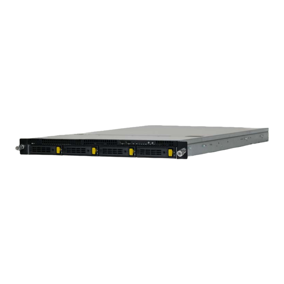
Two Intel ® Server System product families integrate the S2600WT, they are the 1U rack mount Relion 1900e product family and the 2U rack mount Relion 2900e product family. Relion 1900e Figure 36. Relion 1900e Table 67. Relion 1900e Product Family Feature Set... - Page 165 Relion 1900e/2900e Manual Feature Description • DB-15 Video connectors Front and Back on non-storage systems Back only on storage systems (12 x 3.5” and 24 x 2.5” drive support) • RJ-45 Serial Port A connector • Dual RJ-45 Network Interface connectors supporting either : External I/O 10 GbE RJ-45 connectors (Intel Server Board Product Code –...
- Page 166 Relion 1900e/2900e Manual Feature Description • Integrated Baseboard Management Controller, IPMI 2.0 compliant • Support for Intel ® Server Management Software Server Management • On-board RJ45 management port • Advanced Server Management via an Intel ® Remote Management Module 4 Lite (Accessory Option)
-
Page 167: Table 68. Relion 2900E Feature Set
Relion 1900e/2900e Manual Relion 2900e Figure 37. Relion 2900e Table 68. Relion 2900e Product Family Feature Set Feature Description Chassis Type 2U Rack Mount Chassis • Relion 2900e w/Dual 1GbE ports – S2600WT2R Server Board Options • Relion 2900e w/Dual 10GbE ports – S2600WTTR •... - Page 168 Relion 1900e/2900e Manual Feature Description • DB-15 Video connectors Front and Back on non-storage systems Back only on storage systems (12 x 3.5” and 24 x 2.5” drive support) • RJ-45 Serial Port A connector • Dual RJ-45 Network Interface connectors supporting either : 10 GbE RJ-45 connectors (Intel Server Board Product Code –...
- Page 169 Relion 1900e/2900e Manual Feature Description • 10 x SATA 6Gbps ports (6Gb/s, 3 Gb/s and 1.5Gb/s transfer rates are supported) • Two single port SATA connectors capable of supporting up to 6 Gb/sec • Two 4-port mini-SAS HD (SFF-8643) connectors capable of supporting up to 6 Gb/sec /SATA •...
- Page 170 Relion 1900e/2900e Manual Glossary This appendix contains important terms used in this document. For ease of use, numeric entries are listed first (for example, “82460GX”) followed by alpha entries (for example, “AGP 4x”). Acronyms are followed by non-acronyms. Term Definition...
- Page 171 Relion 1900e/2900e Manual Term Definition Intel ® Architecture Input Buffer I/O Controller Hub ICMB Intelligent Chassis Management Bus IERR Internal Error I/O and Firmware Bridge Independent Loading Mechanism Integrated Memory Controller INTR Interrupt I/OAT I/O Acceleration Technology I/O Hub Internet Protocol...
- Page 172 Relion 1900e/2900e Manual Term Definition Programmable Logic Device Platform Management Interrupt POST Power-On Self Test PSMI Power Supply Management Interface Pulse-Width Modulation QuickPath Interconnect Random Access Memory RASUM Reliability, Availability, Serviceability, Usability, and Manageability RISC Reduced Instruction Set Computing RMII...
-
Page 173: Reference Documents
Remote Management Module 4 Technical Product Specification Intel ® Remote Management Module 4 and Integrated BMC Web Console Users Guide Relion 1900e Technical Product Specification Relion 2900eTechnical Product Specification Intel ® Ethernet Controller I350 Family Product Brief ... - Page 174 Relion 1900e/2900e Manual NOTES __________________________________________________________________________________________________ __________________________________________________________________________________________________ __________________________________________________________________________________________________ __________________________________________________________________________________________________ __________________________________________________________________________________________________ __________________________________________________________________________________________________ __________________________________________________________________________________________________ __________________________________________________________________________________________________ __________________________________________________________________________________________________ __________________________________________________________________________________________________ __________________________________________________________________________________________________ __________________________________________________________________________________________________ __________________________________________________________________________________________________ __________________________________________________________________________________________________ __________________________________________________________________________________________________ __________________________________________________________________________________________________ __________________________________________________________________________________________________ __________________________________________________________________________________________________ __________________________________________________________________________________________________ __________________________________________________________________________________________________ __________________________________________________________________________________________________ __________________________________________________________________________________________________ __________________________________________________________________________________________________ __________________________________________________________________________________________________ __________________________________________________________________________________________________ __________________________________________________________________________________________________ __________________________________________________________________________________________________ __________________________________________________________________________________________________ __________________________________________________________________________________________________ __________________________________________________________________________________________________ __________________________________________________________________________________________________ __________________________________________________________________________________________________ __________________________________________________________________________________________________ Revision 1.3...
Need help?
Do you have a question about the Relion 1900e and is the answer not in the manual?
Questions and answers