Table of Contents
Advertisement
Quick Links
Advertisement
Table of Contents

Subscribe to Our Youtube Channel
Related Manuals for Penguin Computing Relion 1400


Summary of Contents for Penguin Computing Relion 1400
- Page 1 1U Server Chassis User Manual (SCSI) Mar. 2005 (Revision A,6) P/N: 1230B0001801...
- Page 2 © 2004-2005 Inventec Enterprise System Corporation (IESC). All rights reserved. All product names or brands mentioned herein are the trademarks of IESC or their respective owners.
-
Page 3: Table Of Contents
About This Manual ............................i Conventions..............................i Package Contents ............................i Standard Components..........................i Optional Components..........................i Safety Precautions ............................ii Operation Safety............................ii Electrical Safety ............................ii Tools Required ............................iii Regulatory and Integration Information.....................iv Regulatory Compliance Identification Numbers..................iv Product Regulatory Compliance ......................iv Battery Replacement Notice........................vi Power Cords ............................vii Product Introduction .........................1-1 Product Features...........................1-1 System Overview .........................1-3... - Page 4 3.1.5 Backplane Power Cable......................3-4 3.1.6 C Signal Cable ........................3-5 3.1.7 System Fan Cables .......................3-6 Cable Vent Baffle .........................3-8 Power Supply ..........................3-9 Server Installation ........................3-10 Power On............................3-12 Figure 1-1 Product Introduction ......................1-1 Figure 1-2 Server Chassis Layout .....................1-3 Figure 1-3 Front View ........................1-4 Figure 1-4 Power Button and System LEDs ..................1-4 Figure 1-5 Back View........................1-6 Figure 1-6 NIC LED .........................1-6...
- Page 5 Figure 2-28 Fixing the CD-ROM daughter card to the CD-ROM ..........2-14 Figure 2-29 Locating the CD-ROM into the place................2-15 Figure 2-30 Fixing the CD-ROM with screws ................2-15 Figure 2-31 Front panel Location....................2-16 Figure 2-32 Inserting the front panel to the slot ................2-16 Figure 2-33 Fixing the front panel ....................2-16 Figure 2-34 Riser Card Assembly Location ..................2-17 Figure 2-35 Riser Card ........................2-17...
-
Page 6: About This Manual
About This Manual You are reading the Server user manual. This manual provides general and specific information about this server. -
Page 7: Conventions
To make sure that you perform certain tasks properly, take note of the following symbols used throughout this manual. Warning: Information to prevent injury to yourself when trying to complete a task. Information to prevent damage to the components when trying to complete Caution: a task. -
Page 8: Safety Precautions
Observe the following safety precautions when you are connecting or disconnecting any device. Operation Safety Important • Any operation on this server must be conducted by certified or experienced engineers. • Before operating your server, carefully read all the manuals included with the server package. •... -
Page 9: Tools Required
Caution • This product is equipped with a three-wire power cable and plug for user’s safety. Use the power cable with a properly grounded electrical outlet to avoid electric shock. Important Motherboards, adapters, and disk drives are sensitive to static electricity discharge. These devices are wrapped in antistatic bags to prevent this damage. -
Page 10: Regulatory And Integration Information
Regulatory Compliance Identification Numbers For the purpose of regulatory compliance certifications and identification, this server is assigned a series number. This server series number can be found on the product label, along with the required approval markings and information. When requesting certification information for this product, always refer to this series number. - Page 11 Class B Equipment This equipment has been tested and found to comply with the limits for a Class B digital device, pursuant to Part 15 of the FCC Rules. These limits are designed to provide reasonable protection against harmful interference in a residential installation. This equipment generates, uses, and can radiate radio frequency energy and, if not installed and used in accordance with the instructions, may cause harmful interference to radio communications.
-
Page 12: Battery Replacement Notice
Canadian Notice (Avis Canadien) Class B Equipment This Class B digital apparatus meets all requirements of the Canadian Interference-Causing Equipment Regulations. Cet appareil numérique de la classe B respecte toutes les exigences du Règlement sur le matériel brouilleur du Canada. Japanese Notice Taiwanese Notice Battery Replacement Notice... -
Page 13: Power Cords
Batteries should not be littered with the general household waste. Please use the public collection system or return them to the supplier. Power Cords The power cord set included in the server meets the requirements for use in the country where the server was purchased. -
Page 14: Product Introduction
Chapter 1 Product Introduction This chapter describes the features of this server. It includes specifications and system overview. -
Page 15: Product Features
This chapter describes the external features of this server. It includes specific sections that identify these features and specifications. The whole picture of this server is shown as below. Figure 1-1 Product Introduction ® ® The server board is configured for the motherboard that uses Intel E7520 MCH, Intel ICH5R and ®... - Page 16 • Integrated Super I/O: Winbond W83627HF controller that supports one serial port, one PS/2 keyboard port, and one PS/2 mouse port. • Expansion Slot: One full-length 64bit/133MHz PCI-X slot for riser card or other expansion card. 1230B0001801 Product Introduction...
-
Page 17: System Overview
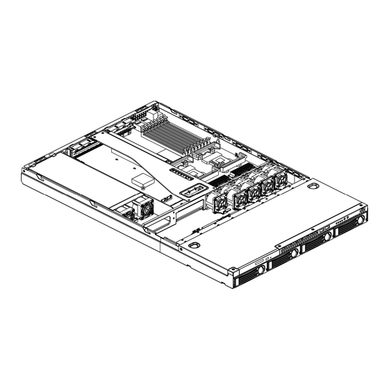
1.2.1 Server Chassis Layout Figure 1-2 Server Chassis Layout Motherboard HDD Bays Fan Duct Slim CD-ROM Fan Module Riser Card Board Assembly Backplane Power Supply Front Panel 1230B0001801 Product Introduction... -
Page 18: 1.2.2 Front View
1.2.2 Front View The front view of this server allows easy access to Hot-Swap HDDs. The power button, USB ports and system LED indicators are also located on the front panel. Figure 1-3 Front View Slim CD-ROM HDD 1 Bay HDD LED HDD 2 Bay Front Panel... -
Page 19: Table 1-1 Front Panel Led Information
LED Information Front panel status LEDs allow constant monitoring of basic system functions while the server is operating. Color Status Power Green On (Steady) Power on Blinking System is in power saving state Power off Amber On (Steady) 1Gbps link Blinking 1Gbps Activity Green... -
Page 20: 1.2.4 Back View
1.2.4 Back View The server back view includes the connectors of the system devices and a slot for an expansion card. Figure 1-5 Back View Dual USB Port Serial Port PS/2 Mouse Port D-sub VGA Port NIC1 Connector (RJ45) AC Power Connector NIC2 Connector (RJ45) PS/2 Keyboard Port LED Information... -
Page 21: Hardware Operation
Chapter 2 Hardware Operation This chapter provides information and procedures for installing or removing the hardware options on Server. -
Page 22: Before You Start
This chapter describes the hardware setup procedures that you have to perform when installing system components. It also gives detailed information on the internal components and how to install them. Take note of the following operations before you start to install or remove any internal components. 2.1.1 Power Off The server does not completely power off when the front panel power button is pressed. -
Page 23: Chassis Cover
Disconnect the power cord first from the AC outlet and then from the server. Figure 2-2 Disconnecting the power cord This server chassis is a 1U form factor designed for easy assembly and disassembly, making the installation of internal components very convenient. Important: Before you install or remove the chassis cover, make sure the power is off. -
Page 24: Figure 2-5 Sliding The Rear Top Cover To The Front
To install the rear top cover: Put the rear top cover into the slot, and slide the rear top cover toward the front until the right position and close the rear top cover. Figure 2-5 Sliding the rear top cover to the front Tighten the rear top cover with the screw on the top. -
Page 25: Figure 2-7 Removing The Rear Top Cover
To Remove the Cover To remove the rear top cover: Loosen the screw on the top of the rear top cover. Press the button as the arrow shows. Slide the rear top cover horizontally to the back panel. Figure 2-7 Removing the rear top cover To remove the front top cover: Loosen the screws on the top and side of the front top cover. -
Page 26: Motherboard
This section tells how to install the motherboard onto the chassis, for the main components operation on the motherboard, please refer to the board manual. The location of the motherboard on the server is shown as below: Figure 2-10 Motherboard Location Important: •... -
Page 27: Figure 2-11 Installing The Motherboard
To install the motherboard: 1. Put the motherboard on the chassis in the correct way. 2. Place 10 screws in the holes indicated by circles to secure the motherboard to the chassis. Figure 2-11 Installing the motherboard Caution: Do not over-tighten the screws. Doing so may damage the motherboard. Reverse steps 1 through 2 to remove the motherboard. -
Page 28: Power Supply
The location of power supply on the server chassis is shown as below: Figure 2-12 Power Supply Location Important: Before you install or remove the power supply, make sure the power is off. To power off the server, see “2.1.1 Power Off”. To install the power supply: Insert the power supply with an angle of inclination to make it locked with the back... -
Page 29: System Fans
Subdividing the motherboard area and the disk drives area is a metal bracket that holds the system fans. The server supports four system fan modules and one single PCI-X fan. The fans are located on the fan bracket. These fans maintain the ideal temperature for the motherboard and disk drives. The location of the system fan on the server chassis is shown as below. -
Page 30: Figure 2-17 Fixing The System Fan
Press the system fan down to make the guide pin through the hole on the fan clip. Figure 2-17 Fixing the system fan Reverse steps 1 through 2 to remove the system fan. 1230B0001801 Hardware Operation... -
Page 31: Backplane For Scsi Hdd
The backplane supports four SCSI HDDs in the system. The design incorporates a Hot-Swap feature to allow easy installation of HDDs. The backplane connector connects to the motherboard to indicate the access and failure for HDDs. Figure 2-18 Backplane for SCSI Backplane Power Connector Fan Power Connector CD-ROM Power Connector... -
Page 32: Figure 2-20 Fixing The Backplane
Push the backplane to the direction as the arrow shows to lock it. Fix it with one screw. Figure 2-20 Fixing the backplane Reverse steps 1 through 3 to remove the backplane. 1230B0001801 Hardware Operation 2-11... -
Page 33: Hdds
This server system comes up with four externally accessible HDD assemblies. The location of HDD on the server chassis is shown as below. Figure 2-21 HDD Assembly Location Important: • Take note of the drive tray orientation before you slide it out. •... -
Page 34: Figure 2-23 Inserting The Hdd Assembly Into The Bay
Carefully insert the HDD assembly into the bay with the lever lifted until it completely enters the bay. Figure 2-23 Inserting the HDD assembly into the bay Push the lever back in place. Turn the lock on the lever clockwise to secure the HDD. -
Page 35: Cd-Rom
Slide the HDD assembly out of the HDD bay. Figure 2-26 Sliding the HDD assembly out of the HDD bay The location of CD-ROM on the server chassis is shown as below. Figure 2-27 CD-ROM Location Important: Before you install or remove the CD-ROM, make sure the power is off. To power off the server, see “2.1.1 Power Off”. -
Page 36: Figure 2-29 Locating The Cd-Rom Into The Place
Locate the CD-ROM right into the place and lock it with the side clips. Figure 2-29 Locating the CD-ROM into the place Fix the CD-ROM with two screws. Figure 2-30 Fixing the CD-ROM with screws Reverse steps 1 through 3 to remove the CD-ROM. 1230B0001801 Hardware Operation 2-15... -
Page 37: Front Panel
The location of front panel on the server chassis is shown as below. Figure 2-31 Front panel Location Important: Before you install or remove the front panel, make sure the power is off. To power off the server, see “2.1.1 Power Off”. To insert the front panel Insert the front panel into the slot with an angel of inclination and press it down... -
Page 38: Riser Card Assembly
The location of riser card assembly on the server chassis is shown as below. Figure 2-34 Riser Card Assembly Location The motherboard has a 64bit/133MHz PCI-X expansion slot. The slot requires a PCI-X riser card (P64-1U) to accommodate a PCI-X expansion card. The riser card comes with the system package. The riser card golden fingers connect to the PCI-X slot on the motherboard. -
Page 39: Figure 2-37 Inserting The Expansion Card To The Slot
Insert an expansion card into the expansion slot by aligning the expansion card with the board guide and sliding the expansion card into the slot until the board seats firmly. Tighten the screw. Figure 2-37 Inserting the expansion card to the slot Press down the riser card assembly firmly until it is seated in the expansion slot on the server board. - Page 40 Chapter 3 Cables and Server Installation This chapter provides the details of all the necessary cables connection and server installation.
-
Page 41: Cables And Server Installation
This chapter provides the details of all the necessary cables connection and server installation for 1U Server Chassis. This section contains figures showing cable locations and descriptions of the connection procedures. 3.1.1 Front Panel Cables Front Panel Cable Connect one end of the front panel cable to the connector on the motherboard. -
Page 42: 3.1.2 Power Cables
Front Panel USB Cable Connect one end of the front panel USB cable to USB header on the motherboard. Figure 3-3 Connecting the front panel USB cable to the motherboard Connect the other end of the front panel USB cable to the USB connector on the front panel. -
Page 43: 3.1.3 Cd-Rom Cables
3.1.3 CD-ROM Cables CD-ROM Cable Connect one end of the CD-ROM cable to the IDE connector on the motherboard. Figure 3-6 Connecting the CD-ROM cable to the motherboard Connect the other end of the CD-ROM cable to the connector on CD-ROM daughter card. -
Page 44: 3.1.4 Scsi Hdd Cable
3.1.4 SCSI HDD Cable Connect one end of the SCSI HDD cable to the connector on the SCSI daughter card. Figure 3-9 Connecting the SCSI HDD cable to the SCSI daughter card Connect the other end of the SCSI HDD cable to the connector on the SCSI backplane. -
Page 45: I 2 C Signal Cable
3.1.6 I C Signal Cable Connect one end of the I C signal cable to the I C ( SMBus) signal connector on the motherboard. Figure 3-12 Connecting the I C signal cable to the motherboard Connect the other end of the I C signal cable to the I C signal connector on the... -
Page 46: 3.1.7 System Fan Cables
3.1.7 System Fan Cables System Fan Cables Connect the fan cables to their respective connectors on the backplane. Figure 3-14 Connecting the system fan cables System Fan Tach Cable Connect one end of the fan tach cable to the fan tach connector on the motherboard. -
Page 47: Figure 3-17 Connecting The System Fan Power Cable To The Motherboard
System Fan Power Cable Connect one end of the fan power cable to the fan power connector on the motherboard. Figure 3-17 Connecting the system fan power cable to the motherboard Connect the other end of the fan power cable to the fan power connector on the backplane. - Page 48 The cable vent baffle is a critical part to the server. Without the part, the sever will reduce thermal performance and make inlet temperature of the power supply over spec. Position the cable vent baffle onto the system fan bracket with the notch upward to insert the bracket in the notch of the sponge.
- Page 49 The system comes with a 500W single power supply with universal AC input that includes PFC and SSI-compliant output cables and connectors. Figure 3-20 Power Supply Assembly P1 Main Power Connector P3 I C Power Connector P2 Processor Power Connector P4 Backplane Power Connector 1230B0001801 Cables and Server Installation...
-
Page 50: Server Installation
To install the rack-mounted server into the rack, complete the procedures described in the following subsections. Important: Ensure that the inner side of the rack rail faces the side of the rack. Carefully align the two front tabs on the front of the fixed rack rail with the holes identified at the front of the rack. - Page 51 Align the rear end of the server rails on the sides of the server with the front end of the rack rails. Insert the server fully into the rack, ensuring that the fixed server rails slide inside the fixed rack rails. Figure 3-23 Inserting the server into the rack Caution: Keep the server parallel to the floor when sliding the fixed server rails into the slide rails.
-
Page 52: Power On
Before you turn on the server, make sure that you have completed the basic system connections. Follow these steps when starting the server. Step 1: Monitor Connection Connect a monitor by plugging a video cable to the video port (blue port) at the back of the server. Step 2: PS/2 Keyboard Connection Plug the keyboard cable into the keyboard port on the back of the server. - Page 53 Step 5: Power on Pressing the power button on the front panel to toggle the server to power. The power LED turns to be green. Figure 3-25 Pressing the power button 1230B0001801 Cables and Server Installation 3-13...
Need help?
Do you have a question about the Relion 1400 and is the answer not in the manual?
Questions and answers