Table of Contents
Advertisement
Quick Links
Advertisement
Table of Contents

Related Manuals for Dog trace d-fence 6th SENSE


Summary of Contents for Dog trace d-fence 6th SENSE
- Page 1 d-fence SENSE Electronic invisible fence User Guide...
- Page 2 Declaration of Conformity VNT electronics s.r.o. Smetanovo náměstí 104 570 01, Litomyšl IČO: 64793826 declares under own responsibility that the product: Electronic invisible fence Dogtrace d-fence is in compliance with essential requirements and other relevant provisions of Directive 1999/5/EC from 9. 3. 1999 meets requirements of General Licence of The Czech Telecommunication Office according to general licence no.
-
Page 3: Table Of Contents
Table of contents Table of contents............3 Introduction . -
Page 4: Package Contents
Waterproof receiver. ■ Receiver battery life up to six months. ■ Non-contact magnetic switch for changing the receiver modes. ■ Eight levels of stimulation impulse. ■ Function ISIT - Interference Signal Intensity Test. ■ For safety reasons the d-fence receiver stops emitting stimulation ■... -
Page 5: How The D-Fence Works
How the d-fence works The electronic invisible system d-fence consisting of the transmitter unit, ■ the antenna wire and the receiver attached to a collar worn by the dog will help you to define the boundaries of a safe play area for your dog (such as your garden) without the risk of escaping. -
Page 6: Transmitter Unit
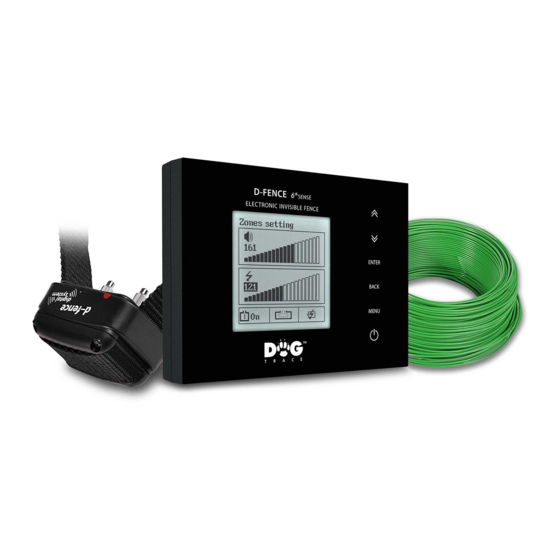
Transmitter unit Description 1 - Backlit graphic LCD 2 - Touch panel control 3 - Antenna wire connector 4 - Power supply adapter connector Buttons function – this button switches on and off the transmitter unit. ■ MENU – this button displays the main menu. ■... - Page 7 Back-up battery pack insertion A rechargeable, back-up battery pack is provided to supply power during a power outage. The back-up battery pack will provide up to sixteen hours of run time for the transmitter unit (see the section Back-Up Battery Power Indicator).
-
Page 8: Receiver Settings
Receiver settings Description 1 - Contact points 2 - Strap 3 - Target 4 - LED indicator Battery insertion and replacement Unscrew the 4 screws of the top of the receiver using a cross-head ■ screwdriver and remove the lid. Insert the 3V lithium CR2 battery into the battery compartment. - Page 9 Checking the battery power LED indicator situated on the receiver‘s front cover under the sign "d-fence" indicates the status of the battery. Red light indicates low battery. Prepare a spare 3V lithium battery CR2 and follow the instructions described in the section Battery insertion and replacement.
- Page 10 The following table shows different modes of the receiver. The intensity level of stimulation impulse must be set according to the size, sensitivity and reaction of each dog. Mode Number of beeps Stimulation impulse level high ISIT function Note: The receiver is set in mode 1 by default. Choosing the contact points The stimulation is delivered through the receiver contact points.
-
Page 11: Antenna Wire Installation
Antenna wire installation Antenna wire must create an uninterrupted loop starting and ending at the transmitter unit. Before you start with the antenna wire installation it might be useful to sketch a rough map of your property showing the wire installation and places of antenna wires connection. - Page 12 min.1,5 m Type 4: Setting the boundary on one or more sites of the garden. The wire runs along the border of the prohibited area and returns back about 1,5 m from the top/ bottom/ front or beyond the boundary according to the possibilities. min.1,5 m Type 5: Creation of the free passage for the dog in a simple wiring by installing wire under /...
- Page 13 Installation Lay the wire along your proposed boundary creating a loop. The antenna ■ wire can be placed on the ground, under the ground, on a fence or a wall in such case it is recommended to install the wire about 30 cm above the ground or as high as where the dog wears the receiver).
-
Page 14: Transmitter Unit Settings
Tip: It is recommended to create a short testing loop (e.g. 2 m) to test the correct function of the system in places where you plan to install the antenna wire and where the receiver detected an interfering signal. Plastic boundary flags (Optional accessories) The plastic boundary flags are a temporary visual aid for your dog during training, and will be removed once your dog is familiar with the boundaries. - Page 15 Setting up the transmitter unit for a short or a long installation of an antenna wire. d-fence 6th SENSE - 2 generation enables you to switch over the transmitter unit power, which is generated into the antenna wire. This function allows a fine setting of warning and correction zone for a short installation (up to 400 m wire installation) and also for a long installation (above 400 m wire installation).
- Page 16 Now you can plug in the antenna connector with an antenna loop into ■ the antenna socket transmitter unit. Zones settings The width of the warning and the correction zone can be set easily on the transmitter unit. Both zones are independent of each other making it possible to set either the warning zone or the correction zone.
- Page 17 antenna wire about 30 cm above the ground or as high as where the dog wears the receiver. Adjust the zone setting (0 - 600) on the transmitter unit by pressing the buttons until the receiver emits stimulation impulses together with the sound signals at approximately one second intervals.
- Page 18 Antenna wire indicator The antenna wire indicator at the left bottom corner of the screen displays the status of the antenna wire. Antenna wire is connected and uninterrupted. Antenna wire is disconnected, interrupted or transmitter unit calibration was performed by mistake while antenna wire connected.
-
Page 19: Training Method
Training method Getting started with the electronic invisible training fence You can use the device with a six month old puppy that has already completed the basic training. It is not recommended to use the device with dogs that are not in a good physical condition (e.g. heart problems, epilepsy, etc.), pregnant or nursing bitches and dogs who have behaviour disorders. - Page 20 performance of the collar unit and whether or not the dog will receive the stimulation impulses. A loose collar can also result in skin irritations. The collar should be tight enough to fit two fingers between the collar and your dog‘s neck, but not so tight that it restricts your dog‘s breathing. It is possible to check the current mode of the receiver.
- Page 21 The transmitter is not waterproof. Protect from water intrusion. ■ During the thunderstorm, disconnect the adapter from the electric ■ outlet and unplug the antenna connector. If the receiver is not in use for 3 months or more, remove the battery. ■...
-
Page 22: Troubleshooting
Using d–fence in winter When using d–fence in winter, please keep in mind: Low humidity – causes less skin conductivity. It is necessary to provide ■ better conductivity between the contact points of the receiver and the dog‘s skin. This can be achieved by lubricating the dog’s skin in the point of contact with vaseline, baby oil, hand lotion, etc. - Page 23 for a given length of antenna wire installation (0,75 mm , 1 mm , 1,5 mm or 2,5 mm ), the resistance value should be maximum 2 Ω per 100 m of wire. For example, if you use three packages of wire (one package is 100 m), the electric resistance of the wire should be maximum 6 Ω.
-
Page 24: Technical Specifications
Technical specifications Transmitter Model 202/2002 ......for installations up to 2200 m ■ Warning zone ....width of the zone from 0 to minimum 7 m ■... -
Page 25: Warranty Terms And Conditions
Warranty terms and conditions VNT electronics s.r.o. provides a 2-year warranty on the Dogtrace products with respect to defects in material and workmanship under normal use and service from the date of the original purchase. The limited warranty does not cover the following: batteries ■... -
Page 26: Installation Drawing
Installation drawing Here is the space for your drawing of your antenna wire installation and note of connection locations. Notes:... -
Page 27: Wall-Mount Screw Hole Template
Cut here... -
Page 28: Certificate Of Warranty
Certificate of warranty Manufacturer: VNT electronics s.r.o. Smetanovo náměstí 104 570 01 Litomyšl Czech Republic Phone: +420 733 121 890 www.dogtrace.com Copying of this user guide is strictly prohibited without the prior written consent of VNT electronics s.r.o. Version 2016-5-11 / EN...
Need help?
Do you have a question about the d-fence 6th SENSE and is the answer not in the manual?
Questions and answers