Table of Contents
Advertisement
Quick Links
Advertisement
Table of Contents
Troubleshooting

Related Manuals for Scotchman CPO 350


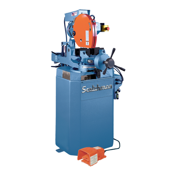
Summary of Contents for Scotchman CPO 350
- Page 1 CPO-350 VARIABLE SPEED COLD SAW PRINTED SEPTEMBER 2014 ‚...
-
Page 2: Table Of Contents
TABLE OF CONTENTS SECTION DESCRIPTION PAGE # INTRODUCTION SAFETY PRECAUTIONS WARRANTY INSTALLATION & SET-UP Physical Dimensions Machine Moving Procedures Physical Inspection Electrical Requirements Machine Start-up Guard Adjustment Coolant System MAINTENANCE & LUBRICATION Lubrication Cutting Oils & Lubricants Scheduled Maintenance MACHINE OPERATION Installing Blades Saw Capacities Selecting The Proper Blade &... - Page 3 TABLE OF CONTENTS SECTION DESCRIPTION PAGE # Electrical Trouble Shooting Breakage or Excessive Dulling of Blades Coolant System Gear Replacement PARTS LISTS Saw Head Vise Assembly Guard Assembly Motor Assembly Electrical Unit Coolant Pump Cast Base & Pedestal Material Stop 30 Inch (76 CM) Variable Speed Motor Control 9.10 Cast Saw Blade Cabinet...
-
Page 4: Introduction
1.0 INTRODUCTION The CPO-350 Variable Speed Cold Saw is designed to cut solids, tubes, flats and other profiles in grades of material that range from hot and cold rolled steel, annealed tool steels, stainless, aluminum, brass, copper, synthetics and extrusions. Cold sawing is a process similar to a milling process. In most cases, this, combined with the self centering vise feature and the variable speed drive, gives a finished cut that does not require any secondary machining or de-burring. -
Page 5: Warranty
11. This machine is top heavy and must be anchored to the floor. 3.0 WARRANTY Scotchman Industries, Inc. will, within three years of the date of purchase, replace F.O.B. the factory or refund the purchase price for any goods which are defective in materials or workmanship, provided the buyer, at the seller’s option, returns the defective goods freight and delivery prepaid to the seller, which... -
Page 6: Installation & Set-Up
4.0 INSTALLATION AND SET-UP Ö CAUTION: THIS SECTION DISCUSSES INSTALLATION, SET-UP AND START-UP PROCEDURES. PLEASE READ IT THOROUGHLY BEFORE OPERATING THIS MACHINE. IF YOUR MACHINE IS EQUIPPED WITH EITHER THE POWER VISE OR THE POWER DOWN FEED OPTION, READ ALL SECTIONS CONCERNING THESE OPTIONS BEFORE OPERATING THE SAW. - Page 7 FIGURE 1 PAGE 7...
-
Page 8: Machine Moving Procedures
4.2 MACHINE MOVING PROCEDURES SEE FIGURE 2 BELOW. FIGURE 2 PAGE 8... -
Page 9: Physical Inspection
This machine is shipped on a pallet and can be moved to the installation location by means of a forklift. Ö CAUTION: THIS MACHINE IS TOP HEAVY AND MUST BE MOVED WITH CARE, ON HARD FLAT SURFACES ONLY. All saws, except models equipped with the power down feed option, are shipped with the head locked in the DOWN position. -
Page 10: Electrical Requirements
4.4 ELECTRICAL REQUIREMENTS SEE FIGURE 3-1 THROUGH 3-4 ON THE FOLLOWING PAGES. Ö CAUTION: TO PREVENT DAMAGE TO THE MACHINE AND DANGER TO THE OPERATOR, ALL ELECTRICAL CONNECTIONS SHOULD BE MADE BY A QUALIFIED ELECTRICIAN. THIS MACHINE OPERATES WITH LIQUID COOLANT AND MUST BE GROUNDED IN ACCORDANCE WITH NATIONAL ELECTRIC CODES. - Page 11 350 VS POWER DOWN 230 VOLT SEE PAGE 47 FOR POWER DOWN WIRING. FIGURE 3-1 PAGE 11...
- Page 12 350 VS MANUAL & PK 230 VOLT FIGURE 3-2 PAGE 12...
- Page 13 350 VS POWER DOWN 460 VOLT SEE PAGE 47 FOR POWER DOWN WIRING. FIGURE 3-3 PAGE 13...
- Page 14 350 VS MANUAL & PK 460 VOLT FIGURE 3-4 PAGE 14...
-
Page 15: Machine Start-Up
On machines equipped with either a power vise or a power down feed, the air supply must also be disconnected and locked or tagged. Scotchman offers a lock-out switch for this machine as an option, if your plant is not equipped with lock-out capabilities. If you are interested in this option, REFER TO SECTION 7.7 or contact your local dealer or the factory. -
Page 16: Guard Adjustment
4.6 GUARD ADJUSTMENT-MANUAL MACHINES SEE FIGURE 4 ON THE FOLLOWING PAGE. FOR GUARD ADJUSTMENT PROCEDURES ON SAWS EQUIPPED WITH THE POWER DOWN FEED OPTION, REFER TO SECTION 7.2C. The proper adjustment of the blade guard on this machine is crucial to the operation of the machine and the safety of the operator. - Page 17 FIGURE 4 PAGE 17...
-
Page 18: Coolant System
4.7 COOLANT SYSTEM The coolant reservoir has a capacity of ten (10) gallons (37.8 liters). One gallon of coolant is shipped with the saw. For normal cutting, it should be mixed in a ratio of one part coolant to seven parts water. In conditions of heavier cutting, the ratio of water should be reduced to five parts. - Page 19 FIGURE 5 PAGE 19...
-
Page 20: Cutting Oils & Lubricants
5.2 CUTTING OILS AND LUBRICANTS SECTION 10.6 lists Scotchman’s parts numbers for cutting oils and lubricants. Using high quality lubricants and oils will greatly increase the life of this equipment. We recommend using only pure, synthetic, water soluble cutting oil for coolant. -
Page 21: Scheduled Maintenance
5.3 SCHEDULED MAINTENANCE A program of scheduled maintenance should be set up and documented according to your application and the frequency you use this machine. The following is a list of some important things that should be included in a scheduled maintenance program. 1. -
Page 22: Machine Operation
6.0 MACHINE OPERATION 6.1 INSTALLING BLADES-MANUAL MACHINES SEE FIGURE 6 BELOW. FOR INSTALLING BLADES ON MACHINES EQUIPPED WITH THE POWER DOWN FEED OPTION, REFER TO SECTION 7.2D. FIGURE 6 PAGE 22... - Page 23 Ö CAUTION: USE ONLY HIGH SPEED STEEL BLADES DESIGNED FOR THIS MACHINE. DO NOT MODIFY ANY BLADE TO FIT THIS MACHINE. DO NOT USE BLADES DESIGNED FOR THIS MACHINE ON ANY OTHER EQUIPMENT. The CPO-350 saw is designed to use a maximum 14 inch (350mm) diameter blade. The arbor size is 40mm with four 12mm pins spaced at 64mm.
-
Page 24: Saw Capacities
6.2 SAW CAPACITIES SEE FIGURE 7 BELOW. FIGURE 7 Figure 8 above is a chart showing the maximum capacities of this machine in various materials at the most common angles from 0 degrees to 90 degrees. PAGE 24... -
Page 25: Selecting The Proper Blade & Cutting Speed
6.3 SELECTING THE PROPER BLADE AND CUTTING SPEED In cold sawing, there is no such thing as a general purpose blade. To achieve the best results from your saw, proper blade selection is important. Each saw is shipped with a pitch (number of teeth) calculator, which will help to determine the proper blade for your application. -
Page 26: Material Clamping
6.4 MATERIAL CLAMPING All work pieces must be clamped securely in the vise. Any slippage of the material can result in broken or damaged blades. The material should be clamped so that the contact surface between the material and the blade is as small as possible. For this reason, when cutting flat stock material, we recommend standing it up and cutting it through the thinnest section, whenever possible. - Page 27 FIGURE 8 FIGURE 9 PAGE 27...
-
Page 28: Miter Locking Device
6.5 MITER LOCKING DEVICE SEE FIGURE 10 ON THE FOLLOWING PAGE. All models manufactured for domestic sales are equipped with a miter locking device which allows quick set-up for mitering at 45 degrees, left and right, and 90 degrees for straight cutting. A miter locking device is available as an option for models manufactured for international sales. - Page 29 FIGURE 10 PAGE 29...
-
Page 30: Optional Equipment
7.0 OPTIONAL EQUIPMENT 7.1 POWER VISE The power vise is an option that is normally ordered with the saw. A retrofit kit is available from your local dealer or the factory. The kit includes all parts required, plus complete installation instructions. The power vise allows automatic clamping of the material, which improves productivity and reduces operator fatigue. - Page 31 THE FOLLOWING ARE SET-UP AND MAINTENANCE INSTRUCTIONS FOR THE POWER VISE OPTION (RETROFIT OR FACTORY INSTALLED): 1. Before connecting the air supply to the saw, make sure that the filter/lubricating device (A) is full of oil. 2. Slide the shuttle valve (F) on the filter/lubricator device to the closed position. 3.
-
Page 32: B Replacing The Spindle In The Air Vise
7.1B REPLACING THE SPINDLE IN THE AIR VISE SEE FIGURE 12 ON THE FOLLOWING PAGE. 1. Disconnect the machine’s power and air supply. 2. Remove the air lines (A) from the front of the cylinder. 4. Remove the guide pins (D) out through the back of the vise. The head must be moved to the miter position in each direction to remove the pins. - Page 33 FIGURE 12 PAGE 33...
-
Page 34: C Replacing The Seals In The Air Vise
7.1C REPLACING THE SEALS IN THE AIR VISE SEE FIGURE 13 ON THE FOLLOWING PAGE. 1. Open the vise to its full open position. 2. Disconnect the air lines from the cylinder. 3. Remove the jam nut (G), the hand wheel (B) and the locking collar (C) from the front of the spindle. 4. - Page 35 FIGURE 13 PAGE 35...
-
Page 36: Power Down Feed
7.2 POWER DOWN FEED The power down feed option, used in conjunction with the power vise option, changes a manual saw into a semi-automatic saw. These options will increase productivity and reduce operator fatigue. The power down feed option cannot be retrofit to machines with serial number 11940491 and prior in the field. This option can be used on machines with or without the power vise option. - Page 37 FIGURE 14 PAGE 37...
-
Page 38: B Stroke Control Adjustment-Power Down Feed
7.2B STROKE CONTROL ADJUSTMENT (POWER DOWN FEED) SEE FIGURE 15 ON THE FOLLOWING PAGE. Before powering the machine, the up and down strokes of the saw head must be set. The stroke is set by the collars (A & B) on the shaft (C). TO SET THE STROKE: 1. - Page 39 FIGURE 15 PAGE 39...
-
Page 40: C Guard Adjustment-Power Down Feed
7.2C GUARD ADJUSTMENT (POWER DOWN FEED) SEE FIGURE 16 ON THE FOLLOWING PAGE. Ö CAUTION: THE GUARD MUST BE ADJUSTED EVERY TIME THAT THE STROKE OF THE MACHINE IS ADJUSTED. TO ADJUST THE GUARD: 1. Before adjusting the guard, set the up and down stroke of the machine by following the instructions in SECTION 7.2. - Page 41 FIGURE 16 PAGE 41...
-
Page 42: D Installing Blades-Power Down Feed
7.2D INSTALLING BLADES (POWER DOWN FEED) SEE FIGURE 17 ON THE FOLLOWING PAGE. Ö CAUTION: USE ONLY HIGH SPEED STEEL BLADES DESIGNED FOR THIS MACHINE. DO NOT MODIFY ANY BLADE TO FIT THIS MACHINE. DO NOT USE BLADES DESIGNED FOR THIS MACHINE ON ANY OTHER EQUIPMENT. - Page 43 FIGURE 17 PAGE 43...
-
Page 44: E Power Down Feed Trouble Shooting
7.2E POWER DOWN FEED TROUBLE SHOOTING 1. THE HEAD FEEDS DOWN FULL SPEED WITH THE FLOW CONTROL (D) TURNED OFF. Bad check valve (V): Clean or replace it. 2. THE HEAD FEEDS FAST WITH NO CONTROL, HEAD BANGING UP, LOW OIL LEVEL. Add oil (hydraulic oil). -
Page 45: F Power Down Feed Wiring Diagram
7.2F POWER DOWN FEED WIRING DIAGRAM (Ser. #'s 6425 & Up)) FIGURE 19 PAGE 45... -
Page 46: G Pneumatic Schematic (Power Down Feed)
7.2G PNEUMATIC SCHEMATIC (POWER DOWN MACHINES) FIGURE 20 PAGE 46... - Page 47 THIS PAGE LEFT BLANK INTENTIONALLY. PAGE 47...
-
Page 48: Material Supply Tracks
7.3 MATERIAL SUPPLY TRACKS A ten foot roller supply track, that can be bolted to the input side of the saw to support longer pieces of material, is an available option for this saw. The supply tracks can also be bolted end to end, to supply longer tracks, if needed. - Page 49 FIGURE 21 PAGE 49...
-
Page 50: Discharge Tracks With Quick-Loc
7.4 DISCHARGE TRACKS WITH SCALES Roller discharge tracks equipped with either a right or left hand quick-loc are available in two lengths: 60" and 120" (122 & 303 CM). The discharge tracks mount to the machine in place of the 30 inch (76 CM) stop that was provided with the machine. - Page 51 FIGURE 22 PAGE 51...
-
Page 52: Special Vise Jaws
7.5 SPECIAL VISE JAWS Special vise jaws for holding square tubing, rectangular tubing and angle iron are stock items. Jaws for holding thin wall round tubes, profiles and bundles are available on a made-to-order basis. For prices and delivery on special jaws, contact your local dealer or the factory. 7.6 LOCK-OUT DISCONNECT SWITCH A lock-out disconnect switch is available for this machine if your plant is not equipped with lock-out capabilities. -
Page 53: Coolant System
2. Always break in the blade before you start normal cutting. 3. Do not apply excessive down pressure on the workpiece. Excessive down pressure will cause the teeth to remove too large of a chip, resulting in premature dulling or breakage. 4. -
Page 54: Gear Replacement
8.4 GEAR REPLACEMENT SEE FIGURE 23 ON THE FOLLOWING PAGE. 1. Remove the drain plug (A) from the head casting and allow the fluid to drain. 2. Remove the motor from the head. 3. Remove the four bolts (E) from the bearing retainer (F). 4. - Page 55 FIGURE 23 PAGE 55...
-
Page 56: Parts Lists
9.0 PARTS LISTS 9.1 SAW HEAD ITEM PART # DESCRIPTION 077150 Needle Bearing 077322 Worm Shaft 077323 Pivot Bearing 077324 Spacer Ring 077325 Bearing 077330 077326 Spacer Ring 077321 Lock Nut 077328 Gear Wheel 060250 M-10 SHCS 073110 M-10 Lock Washer (Not Pictured) 075080 Key 8 x 7 x 32 073210... - Page 57 077340 Key 10 x 8 x 32 075081 Snap Ring 077864 M-5 x 12 SHCS 201110 M-6 x 12 HHCS 060101 Emergency Stop Mount 060110 Emergency Stop Box 077620 Complete Head Assembly 077860 Head Gasket (Not Pictured) 077630 3/8 BSPT Breather 073692 I Bolt (Not Pictured) FIGURE 24...
-
Page 58: Vise Assembly
9.2 VISE ASSEMBLY ITEM PART # DESCRIPTION 221220 M-10 x 40 SHCS 077319 Cast Grip Cheek (Rear) 077610 Vise Jaw (Right) 077612 Vise Jaw Set (4 Pcs.) 208012 M-10 Hex Nut 077309 Guide Shaft 077310 Seal 077308 Base 077100 Dowel Pin 077133 Screw End 077136... - Page 59 FIGURE 25 PAGE 59...
-
Page 60: Guard Assembly
9.3 GUARD ASSEMBLY (Manual & Power Vise Machines) ITEM PART # DESCRIPTION Guard Shell 077165 Spacer Ring (Thin) Hinge Cap (Front) 077164 Spacer Ring (Thick) Hinge Cap (Rear) 077166 077167 Snap Ring 077160 Plastic Washer Coupling Arm 077162 077161 Locking Ring 077361 Bracket 060490... - Page 61 FIGURE 26 PAGE 61...
-
Page 62: Motor Assembly
9.4 MOTOR ASSEMBLY ITEM PART # DESCRIPTION 076886 Fan Cover 073407 M-5 x 8 SHCS 076887 End Casting 077325 Motor Bearing 077345 203210 M-10 SHCS 077370 Key 6 x 4 x 32mm 077376 Seal Spacer Washer End Casting (Front) 077375 Pinion Gear 077189 Lock Nut... - Page 63 FIGURE 27 PAGE 63...
-
Page 64: Electrical Unit
9.5 ELECTRICAL UNIT ITEM PART # DESCRIPTION 060061 Enclosure With Cover Cover 221002 M-4 x 12 SHCS 060071 Contactor-24 Volt 060072 Terminal Blocks 060083 Contact Block (Power Down Saws) 060063 Ground Lug 060115 Motor Switch Legend Plate 011844 Knob 060090 Motor Cable 060095 Pump Cable... - Page 65 FIGURE 28 PAGE 65...
-
Page 66: Coolant Pump
9.6 COOLANT PUMP ITEM PART # DESCRIPTION 060165 Pump 230V 1PH 060150 230 Volt Coolant Pump 060158 440 Volt Coolant Pump 060160 575 Volt Coolant Pump 060152 Impeller 060157 End Cap 060151 Seal Kit Bolt Bolt 060080 90 Degree Hose Barb 060140 Coolant Line 060095... - Page 67 FIGURE 29 PAGE 67...
-
Page 68: Cast Base & Pedestal
9.7 CAST BASE AND PEDESTAL ITEM PART # DESCRIPTION 077300 Pedestal 078600 Pivot Shaft 077364 Spring Mount (Lower) 077365 Return Spring 221210 M-10 x 25 SHCS 077363 Spring Mount (Upper) 077142 Grease Nipple 077109 Cast Base 660535 Cast Base (Power Vise) 077112 Sieve Screen 073350... - Page 69 FIGURE 30 PAGE 69...
-
Page 70: Material Stop 30 Inch (76 Cm)
9.8 MATERIAL STOP 30 INCH (76 CM) ITEM PART # DESCRIPTION 677436 Stop Clamp 060315 Stop Shaft 060310 Shaft 073460 M-10 x 15 SHCS 076930 Complete Assembly 080193 Wrench PAGE 70... - Page 71 FIGURE 31 PAGE 71...
-
Page 72: Variable Speed Motor Control
9.9 VARIABLE SPEED MOTOR CONTROL ITEM PART # DESCRIPTION 003120 Voltage Sticker (Not Pictured) 078275 230 Volt Variable Speed Control 078276 460 Volt Variable Speed Control 044515 230 V Fuse Variable Speed Drive (3) 044540 460 V Fuse Variable Speed Drive (3) 045557 Variable Speed Switch 045558... - Page 73 FIGURE 32 PAGE 73...
-
Page 74: Cast Saw Blade Cabinet
9.10 SAW BASE CABINET ITEM PART# DESCRIPTION 760115 CPO Base Cabinet 760114 CPO Chip Drawer 760115.8 Pump Mounting Bracket 073420 M-8 x 16 DIN912 SHCS 215013 M-8 Greer Nut 060170 1/8” Clearflex Plastic 060175 Rear Cover Strap 154003 Alum Rivet PAGE 74... - Page 75 FIGURE 33 PAGE 75...
-
Page 76: Optional Equipment Parts Lists
10.0 OPTIONAL EQUIPMENT PARTS LISTS 10.1 POWER VISE ASSEMBLY ITEM PART # DESCRIPTION 077462 Cast Grip Cheek (Front) 077319 Cast Grip Cheek (Rear) 073457 M-6 x 80 SHCS 077460 Screw Spindle 060204 Cylinder Housing 077417 O-Ring 077416 O-Ring 077411 Piston 077418 Roll Pin 060450... - Page 77 FIGURE 33 PAGE 77...
-
Page 78: Power Down Feed Assembly
10.2 POWER DOWN FEED ASSEMBLY ITEM PART # DESCRIPTION 078510 Bracket Assembly (Upper) 221210 M-10 SHCS 077211 Return Spring 078524 Cylinder Pivot 078525 Bracket Assembly (Lower) 140415 1/2" Clevis Pin 078520 Stroke Adjustment Rod 123120 1/8" Cotter Pin 078518 Stroke Adjustment Stop (Upper) 078518 Stroke Adjustment Stop (Lower) 080062... - Page 79 FIGURE 34 PAGE 79...
-
Page 80: A Power Down Feed Controls
10.2A POWER DOWN FEED CONTROLS (SER. #'S B8001 & UP) ITEM PART # DESCRIPTION 077736 Valve Mount Assembly 077183 Cord Connector 077738 90 Degree Swivel x 169 PL 047535 Flow Control Valve 077746 1/4" NPT x 1/4" Street PL 078190 Regulator 077770 1/4"... - Page 81 FIGURE 35 PAGE 81...
-
Page 82: B Power Down Feed Electric Controls
10.2B POWER DOWN FEED ELECTRICAL CONTROLS (SERIAL #'S 8001 & UP) ITEM PART # DESCRIPTION 075250 Enclosure 077183 Cord Grip 075205 Mounting Plate 221002 M-4 x 12 SHCS 078104 End Bracket 078456 M-4 x 6 Terminal Block 078457 Jumper 060044 24 Volt Relay 060104 Cord Grip... - Page 83 FIGURE 36 PAGE 83...
-
Page 84: C Guard Assembly (Power Down Feed)
10.2C GUARD ASSEMBLY (POWER DOWN FEED) ITEM PART # DESCRIPTION Guard Shell (Fixed) 073641 M-10 x 65 SHCS Movable Guard 077167 Snap Ring 077202 Spacer Ring 078516 Guard Stop 073691 M-6 Knob 077165 060140 Coolant Line 077154 Hose Barb 077155 Valve 077770 Pipe Nipple... - Page 85 FIGURE 37 PAGE 85...
-
Page 86: Foot (303 Cm) Supply Track
10.3 TEN FOOT (304 CM) SUPPLY TRACK ITEM PART # DESCRIPTION 029243 Conveyor Assembly 029244 Leg Assembly 204230 M-10 x 100 HHCS 221210 M-10 x 25 HHCS 029245 Roller 076938 Optional Guide Assembly 229225 M-10 x 70 Shoulder Bolt 043003 Guide Roller 214012 M-10 Washer... - Page 87 FIGURE 38 PAGE 87...
-
Page 88: Discharge Tracks (48", 84" & 120")
10.4 DISCHARGE TRACKS W/QUICK-LOC (60 & 120 INCH) ITEM PART # DESCRIPTION COMMON PARTS 029244 Leg Assembly 029241 60" Roller Conveyor 029243 120" Roller Conveyor 029114 Quick-Loc Arm Extension 029175 Rail Mounting Bracket 130107 5/16 x 18 x FSHCS 130212 3/8 x 16 x 1-1/4 C-Bolt 029272 Mounting Bracket... - Page 89 FIGURE 39 PAGE 89...
-
Page 90: Coolants & Lubricants
10.5 COOLANTS AND LUBRICANTS UNIT PART # DESCRIPTION 1 Gal. 075751 Synthetic Coolant 5 Gal. 075752 Synthetic Coolant 55 Gal. 075754 Synthetic Coolant 1 Gal. 075756 Special Mix Coolant 5 Gal. 075757 Special Mix Coolant 1 Qt. 075753 Air Line Lubricant 1 Gal. - Page 91 FIGURE 40 PAGE 91...
-
Page 92: Laser Light
10.7 LASER LIGHT ITEM QTY PART # DESCRIPTION 033258 Laser Rod 065006 Laser Support Arm 065012 CPO Laser 221115 M-8 x 20 DIN 912 SHCS 046668 1/8” Nylon Clamp Laser Transformer 012336 Toggle Switch Laser Connector Plug 60060.2 New Laser Electrical Enclosure 158210 1/4”... - Page 93 FIGURE 41 PAGE 93...
-
Page 94: Stock Blades
11.0 STOCK BLADES ITEM PART # DESCRIPTION 10-3/4 INCH (275 MM) 074309 90 Tooth 074308 100 Tooth 074310 120 Tooth 074311 150 Tooth 074312 180 Tooth 074313 240 Tooth 074314 260 Tooth 12-1/2 INCH (315 MM) 074355 90 Tooth 074356 100 Tooth 074357 110 Tooth... - Page 95 THERE ARE FOUR STYLES OF BLADES AVAILABLE: STYLE 2: Has a round back tooth with a square face and top. This style is designed for thin wall, nonferrous tubes, plastics and synthetics. STYLE 2A: Is an alternate top bevel grind. This grind is used on blades that have 240 teeth or more. Applications for this style are thin wall tubes, profiles with thin cross sections and nonferrous applications that require 240 teeth or more.
Need help?
Do you have a question about the CPO 350 and is the answer not in the manual?
Questions and answers
Where can I purchase 077701(baffle)