Table of Contents
Troubleshooting

Subscribe to Our Youtube Channel
Related Manuals for Scotchman CPO-275


Summary of Contents for Scotchman CPO-275
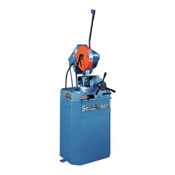
- Page 1 You have downloaded a manual for our MODEL CPO-275 COLD SAW CPO-275 COLD SAW Please download our .pdf "Cold Saw Blade Basics" too. Please read both the manual & the "Cold Saw Blade Basics" before operating this saw!!
- Page 2 MODEL CPO-275 COLD SAW S/N B39330422 & AFTER AUGUST 2023 SCOTCHMAN IND. - 180 E US HWY 14 - PO BOX 850 - PHILIP, SD 57567 Call: 1-605-859-2542...
-
Page 3: Table Of Contents
Power Down Feed Set-up & Maintenance Stroke Control Adjustment (Power Down Feed) Guard Adjustment (Power Down Feed) Installing Blades (Power Down Feed) Page 2 SCOTCHMAN IND. - 180 E US HWY 14 - PO BOX 850 - PHILIP, SD 57567 Call: 1-605-859-2542... - Page 4 Overview of Scotchman Measuring Systems Cutting Coolants & Lubricants 10.8 10.9 Material Stop 30 Inch (76 CM) 11.0 STOCK BLADES Page 3 SCOTCHMAN IND. - 180 E US HWY 14 - PO BOX 850 - PHILIP, SD 57567 Call: 1-605-859-2542...
-
Page 5: Introduction
1.0 INTRODUCTION The CPO-275 Cold Saw is designed to cut solids, tubes, flats and other profiles in grades of material that range from hot and cold rolled steel, annealed tool steels, stainless, aluminum, brass, copper, synthetics and extrusions. Cold sawing is a process similar to a milling process. In most cases, this, combined with the self centering vise feature, gives a finished cut that does not require any secondary machining or de-burring. -
Page 6: Warranty
This machine is top heavy and must be anchored to the floor via the holes in the saw base. 3.0 WARRANTY Scotchman Industries, Inc. will, within three years of the date of purchase, replace F.O.B. the factory or refund the purchase price for any goods which are defective in materials or workmanship, provided the buyer, at the seller’s option, returns the defective goods freight and delivery prepaid to the seller, which... -
Page 7: Installation & Set-Up
4.0 INSTALLATION AND SET-UP CAUTION: THIS SECTION DISCUSSES INSTALLATION, SET-UP AND START-UP PROCEDURES. PLEASE READ IT THOROUGHLY BEFORE OPERATING THIS MACHINE. IF YOUR MACHINE IS EQUIPPED WITH EITHER THE POWER VISE OR THE POWER DOWN FEED OPTION, READ ALL SECTIONS CONCERNING THESE OPTIONS BEFORE OPERATING THE SAW. - Page 8 FIGURE 1 Page 7...
-
Page 9: Machine Moving Procedures
4.2 MACHINE MOVING PROCEDURES SEE FIGURE 2 ON THE FOLLOWING PAGE. This machine is shipped on a pallet and can be moved to the installation location by means of a fork lift. CAUTION : THIS MACHINE IS TOP HEAVY AND MUST BE MOVED WITH CARE, ON HARD, FLAT SURFACES ONLY. - Page 10 LIFTING EYE LIFTING FORKS FIGURE 2 Page 9...
-
Page 11: Physical Inspection
4.3 PHYSICAL INSPECTION Once the machine is located, check it for any possible damage incurred in shipment. Remove the lifting eyelet and install the draw handle. CAUTION: DO NOT USE THE LIFTING EYELET FOR ANY MACHINES OTHER THAN THIS SAW. MAKE SURE THAT THE DRAW HANDLE HAS A JAM NUT ON THE THREADS BEFORE INSTALLING IT ON THE SAW. -
Page 12: Electrical Requirements
THRU 3-4. For supply lines ten feet (303 cm) or shorter, we recommend 12 gauge wire. For lines longer than ten (303 cm), we recommend 10 gauge wire. We do not recommend supply lines over twenty feet (606cm) in length. CPO-275-LT. (30-60 RPM) MOTOR VOLTAGE FULL LOAD CURRENT... - Page 13 MANUAL OR PK W/ TRIGGER SWITCH TRANSFORMER FUSE TRIGGER SWITCH A. Relay B. Main Switch C. Saw Motor A1 1 3 5 13 A2 D. Coolant Pump E. Ground 15 19 23 8 12 16 20 24 MOTOR 1 5 9 13 17 21 6 10 14 18 22 DISCONNECT SUPPLIED BY CUSTOMER...
- Page 14 PKPD W/EMERGENCY STOP (SEE SECTION 7.10 FOR POWER DOWN FEED WIRING DIAGRAM) DIL A-31 24V RELAY BLACK CYL. VALVE P/N 45655 VISE WHITE BLACK UPPER LIMIT SW. N.O. WHITE CYL. VALVE P/N 45655 HEAD BLACK WHITE FOOT PEDAL SWITCH N.O. INCOMING POWER TRANSFORMER FUSE...
- Page 15 1-PHASE MOTOR W/TRIGGER SWITCH INCOMING POWER TRANSFORMER FUSE TRIGGER SWITCH A. Relay B. Saw Motor C. Coolant Pump A1 1 3 5 13 A2 D. Ground 2 4 6 SINGLE PHASE PUMP MOTOR CAPACITOR DISCONNECT SUPPLIED BY CUSTOMER FIGURE 3-3 Page 14...
- Page 16 1-PHASE MOTOR W/E-STOP SERIAL #'S B3431 & UP DIL-ER-31-G 24V RELAY BLACK CYL. VALVE P/N 45655 WHITE BLACK UPPER LIMIT SW. N.O. WHITE CYL. VALVE P/N 45655 A. Relay BLACK B. Main Switch WHITE C. Saw Motor D. Coolant Pump FOOT PEDAL SWITCH N.O.
-
Page 17: Machine Start-Up
On machines equipped with either a power vise or a power down feed, the air supply must also be disconnected and locked or tagged. Scotchman offers a lock-out switch for this machine as an option, if your plant is not equipped with lock-out capabilities. If you are interested in this option, REFER TO SECTION 7.14 or contact your local dealer or the factory. -
Page 18: Frl Use And Maintenance
4.6 FRL USE AND MAINTENANCE SEE FIGURE 4 ON THE NEXT PAGE CAUTION: SHUT OFF AIR SUPPLY BEFORE SERVICING THE FRL The FRL (Filter Regulator Lubricator) is an important and often overlooked item on a cold saw. It helps to keep moisture from contaminating the pneumatic system and adds a little oil to keep the system lubricated. - Page 19 Scotchman Air Line Then pull water trap free. Filter Lubricant is recommended can be removed by squeezing the Qt.
-
Page 20: Guard Adjustment
4.7 GUARD ADJUSTMENT SEE FIGURE 5 BELOW. FOR GUARD ADJUSTMENT PROCEDURES ON SAWS EQUIPPED WITH THE POWER DOWN FEED OPTION, REFER TO SECTION 7.8. The proper adjustment of the blade guard on this machine is crucial to the operation of the machine and the safety of the operator. -
Page 21: Coolant System
4.8 COOLANT SYSTEM The coolant reservoir has a capacity of eight (8) gallons (30.3 liters). One gallon of coolant is shipped with the saw. For normal cutting, it should be mixed in a ratio of one part coolant to seven parts water. In conditions of heavier cutting, the ratio of water should be reduced to five parts. -
Page 22: Cutting Oils & Lubricants
5.2 CUTTING OILS AND LUBRICANTS SECTION 10.8 lists Scotchman’s parts numbers for cutting oils and lubricants. Using high quality lubricants and oils will greatly increase the life of this equipment. We recommend using only pure, synthetic, water soluble cutting oil for coolant. For the saw head, use a non-EP additive ISO-460 gear oil specified for worm gears. -
Page 23: Coolant Pump Maintenance
5.4 COOLANT PUMP MAINTENANCE IF YOUR COOLANT PUMP IS LEAKING OR LACKS POWER, USE THE FOLLOWING STEPS. We recommend replacing the pump seal kit anytime that the pump is dismantled. FOR PART NUMBER IDENTIFICATION, REFER TO SECTION 9.6. Make sure that the power to the machine is off. Remove the four bolts (J) and remove the pump from the machine. - Page 24 FIGURE 7 Page 23...
-
Page 25: Machine Operation
6.0 MACHINE OPERATION 6.1 INSTALLING THE BLADE - MANUAL MACHINES SEE FIGURE 8 BELOW. FOR INSTALLING BLADES ON MACHINES EQUIPPED WITH THE POWER DOWN FEED OPTION, REFER TO SECTION 7.9. THRU CENTER HOLE IN GUARD FIGURE 8 Page 24... - Page 26 DO NOT MODIFY ANY BLADE TO FIT THIS MACHINE. DO NOT USE BLADES DESIGNED FOR THIS MACHINE ON ANY OTHER EQUIPMENT. The CPO-275 saw is designed to use a maximum 10-3/4 inch (275mm) diameter blade. The arbor size is 32mm with two 8mm pins spaced at 45mm.
-
Page 27: Saw Capacities
6.2 SAW CAPACITIES Figure 9 below is a chart showing the maximum capacities of this machine in various materials at the most common angles from 0 degrees to 90 degrees. CPO - 275 #060330 03/21 90° 45° CAPACITIES WITH MAXIMUM DIAMETER BLADES 275 MM INCHES... -
Page 28: Selecting The Proper Blade & Cutting Speed
Selecting the proper blade speed is very important. The CPO-275 LT and HT saws have an RPM range from 30 - 60 (LT) and 60 - 120 (HT). The heavier the material, the lower RPM is best. The lighter the material, the higher RPM is best. -
Page 29: Material Clamping
All models of the CPO-275, except those fitted with the power down feed option, have this down stroke or cutting depth adjustment. SEE FIGURE 11 ON THE FOLLOWING PAGE. This adjustment is used to keep the saw blade from cutting into the vise spindle and must be adjusted when changing sizes of materials or blades. - Page 30 Cut thru the thinnest Cut angle with the web section whenever possible up whenever possible. with tube and solids. P/N 077937 - Square tube Special form jaws for multiple parts jaws for the 275 cold saw. or special shapes FIGURE 10 Bolt and Lock Nut for Adjusting Blade Cutting Depth...
-
Page 31: Miter Locking Device
6.5 MITER LOCKING DEVICE SEE FIGURE 12 ON THE FOLLOWING PAGE. All models manufactured for domestic sales are equipped with a miter locking device which allows quick set-up for mitering at 45 degrees, left and right, and 90 degrees for straight cutting. A miter locking device is available as an option for models manufactured for international sales. - Page 32 FIGURE 12 Page 31...
-
Page 33: Optional Equipment
7.0 OPTIONAL EQUIPMENT 7.1 POWER VISE The power vise is an option that is normally ordered with the saw. It is not recommended as a retro-fit in the field. The power vise allows automatic clamping of the material, which improves productivity and reduces operator fatigue. - Page 34 TO ADJUST THE VISE TO THE SIZE OF MATERIAL BEING CUT: Release the locking collar (D) on the vise spindle (see below). The vise spindle is left hand threaded and the locking collar must be turned clockwise to release it. Open the vise, using the positioning handle (E), and place the material in the vise.
-
Page 35: Replacing The Spindle In The Power Vise
7.3 REPLACING THE SPINDLE IN THE POWER VISE SEE FIGURE 14 BELOW. CAUTION: DISCONNECT THE MACHINE’S POWER AND AIR SUPPLY Disconnect the air lines. The air connections on the cylinder are snap connectors. To release the air connections, push the collar around the hose into the fitting and pull the hose out. To reconnect the lines, simply push the air line into the fitting as far as it will easily go. -
Page 36: Replacing The Seals In The Power Vise
7.4 REPLACING THE SEALS IN THE POWER VISE SEE FIGURE 15 BELOW. CAUTION: DISCONNECT THE MACHINE’S POWER AND AIR SUPPLY SEAL KIT IS P/N 076371 - Contains two small and two large o-rings and an oil seal. Locations below. Open the vise to its full open position. Disconnect the air lines from the cylinder (A). -
Page 37: Power Down Feed
7.5 POWER DOWN FEED The power down feed option, used in conjunction with the power vise option, changes a manual saw into a semi-automatic saw. These options will increase productivity and reduce operator fatigue. The power down feed option will not retrofit to machines with serial number 11940491 and prior in the field. This option can be used on machines with or without the power vise option. - Page 38 FIGURE 16 Page 37...
-
Page 39: Stroke Control Adjustment (Power Down Feed)
7.7 STROKE CONTROL ADJUSTMENT (POWER DOWN FEED) SEE FIGURE 17 ON THE FOLLOWING PAGE. Before powering the machine, the up and down strokes of the saw head must be set. The stroke is set by the collars (A & B) on the shaft (C). TO SET THE STROKE: The saw blade control switch for the saw blade is located in the electrical box on top of the motor. - Page 40 FIGURE 17 Page 39...
-
Page 41: Guard Adjustment (Power Down Feed)
7.8 GUARD ADJUSTMENT (POWER DOWN FEED) SEE FIGURE 18 ON THE FOLLOWING PAGE. CAUTION: THE GUARD MUST BE ADJUSTED EVERY TIME THAT THE STROKE OF THE MACHINE IS ADJUSTED. TO ADJUST THE GUARD: Before adjusting the guard, set the up and down stroke of the machine by following the instructions in SECTION 7.7. - Page 42 DETAIL VIEW FIGURE 18 Page 41...
-
Page 43: Installing Blades (Power Down Feed)
BLADES DESIGNED FOR THIS MACHINE ON ANY OTHER EQUIPMENT. The CPO-275 saw is designed to use a maximum 10-3/4 inch (275mm) diameter blade. The arbor size is 32mm with two 8mm pins spaced at 45mm, also known as 2/8/45 pin spacing. - Page 44 FIGURE 19 Page 43...
-
Page 45: Power Down & Power Vise Trouble Shooting
FOR THE CURRENT ELECTRIC POWER THE PD SOLENOID. DOWN-FEED SYSTEM. Hydraulic Reservoir was overfilled or seals are leaking in the cylinder. SCOTCHMAN IND. - 180 E US HWY 14 - PO BOX 850 - PHILIP, SD 57567 Call: 1-605-859-2542 Page 44... - Page 46 UPPER LIMIT SWITCH POWER DOWN FEED WIRING DIAGRAM (Ser. #'s 6425& Up) OIL RESERVOIR CHECK VALVE LOWER 13 21 LIMIT SWITCH DIL A-31 24V RELAY PD CYLINDER 14 22 FLOW CONTROL VISE CYL. VALVE BLACK WHITE BLACK WHITE PK CYLINDER HEAD UPPER LIMIT SW.
-
Page 47: Material Supply Tracks
Several Guide Assemblies can be mounted to the conveyor if needed. ► NOTE: WE ALSO HAVE COVERED ROLLER CONVEYORS AND SOLID FLAT CONVEYORS AVAILABLE. CONTACT YOUR DEALER OR THE FACTORY FOR MORE INFORMATION OR VISIT WWW.SCOTCHMAN.COM Page 46... - Page 48 EXPLODED VIEW DETAIL VIEW 076938 13" GUIDE ASSEMBLY 029242 - 10' ROLLER CONVEYER W/LEGS WE HAVE COVERED ROLLER CONVEYORS AND SOLID FLAT TABLES (NO ROLLERS) AVAILABLE TOO. SEE AT: WWW.SCOTCHMAN.COM FIGURE 21 Page 47...
-
Page 49: Scotchman Measuring Systems
For more information, please call your dealer or the factory. Or visit our website at: www.scotchman.com Page 48 SCOTCHMAN IND. - 180 E US HWY 14 - PO BOX 850 - PHILIP, SD 57567 Call: 1-605-859-2542... - Page 50 QUICK-LOC 141517 133313 MULTI-LOC DIGITAL QUICK STOP FIGURE 22 Page 49...
-
Page 51: Special Vise Jaws
7.13 SPECIAL VISE JAWS Special vise jaws for holding square tubing, rectangular tubing and angle iron are stock items. Jaws for holding thin wall round tubes, profiles and bundles are available on a made-to-order basis. See Section 6.4 for examples. For prices and delivery on special jaws, contact your local dealer or the factory. - Page 52 UPPER LIMIT SWITCH OIL RESERVOIR CHECK VALVE LOWER LIMIT SWITCH PD CYLINDER FLOW CONTROL PK CYLINDER PK SOLENOID PD SOLENOID FIGURE 23 Page 51...
-
Page 53: Trouble Shooting Guide
8.0 TROUBLE SHOOTING GUIDE 8.1 ELECTRICAL TROUBLE SHOOTING THE MOTOR WILL NOT RUN: A. Some models have a lock-out switch in the base of the saw. If your saw has this option, make sure that it is in the ON position. B. -
Page 54: Breakage Or Excessive Dulling Of Blades
Improper re-sharpening is one of the most common problems encountered in cold sawing. Here at Scotchman Ind. we use only modern CNC equipment operated by experienced people. Keep the blade flange, the face of the blade spindle and the blade clean and free from nicks. Any contamination or nicks on the flange, spindle or the blade will cause the blade to run out of alignment. -
Page 55: Coolant System
8.3 COOLANT SYSTEM IF COOLANT WILL NOT FLOW: A. Check the wiring connections to the pump and make sure that the pump is running in the right direction. The pump has an arrow in the casting to indicate the direction. B. -
Page 56: Gear Replacement
8.4 GEAR REPLACEMENT SEE FIGURE 24 BELOW. Remove the drain plug (A) from the head casting and allow the fluid to drain. Remove the motor (four bolts) from the head. Remove the three bolts (B) from the bearing housing (C) through the access holes in the guard. Remove the spindle shaft (D) with a slide hammer. -
Page 57: Parts Lists
9.0 PARTS LISTS 9.1 SAW HEAD ITEM PART # DESCRIPTION Key 8 x 7 x 32mm 075080 077151 275 Saw Shaft 275 Spindle Cap 077143 075075 Oil Seal 077146 275 Gasket Roller Bearing 075076 275 Spacer Ring 077147 275 Bushing Block 077148 275 Worm Gear (Bronze) 077149... - Page 58 073108 M-8 Lock Washer 221120 M8 x 25 SHCS 080193 M8 Blade Allen Wrench (not shown) 077630 Vent Eye Bolt (Not pictured) 073692 073106 M-6 Lock Washers 275 Saw Head Assembly - Includes Casting, 077107 Shaft w/Bronze Gear & Related - NO pivot shaft, handle or switches.
-
Page 59: Vise Assembly
9.2 VISE ASSEMBLY ITEM PART # DESCRIPTION 221215 M10 x 35 SHCS 077128 275 Saw Jaw with Seal (Rear) 077119 275 Grip Cheek (Right) 208012 M10 Hex Nut 077120 275 Guide Shaft 077310 Seal 077132 275 Vise Base, Sales - (Includes H & I) 077100 Dowel Pin 077133... - Page 60 FIGURE 26 Page 59...
-
Page 61: Guard Assembly
9.3 GUARD ASSEMBLY ITEM PART # DESCRIPTION Complete Guard Assembly 070000 221120 M8 x 25 SHCS 077164 Spacer Ring (Thick) Hinged Cap (Front) 077165 Spacer Ring (Thin) Hinged Cap (Rear) 077166 Nylon Spacer 077167 Snap Ring 077160 M8 Plastic Washer 677163 Coupling Rod 077162... - Page 62 FIGURE 27 Page 61...
-
Page 63: Motor Assembly
9.4 MOTOR ASSEMBLY ITEM PART # DESCRIPTION 076555 275 Fan Cover - EMOD 076890 275 Fan Cover - 1 PH 073444 M4 X 10 DIN912 SHCS 076895 275 Fan Blade 3 PH EMOD 076891 275 Fan - 1 PH 077194 Rear Casting EMOD (Obsolete) 075050 Retaining Ring... - Page 64 078000 275 1PH T-S Motor Assy. 078001 275 1PH E-S Motor Assy. FIGURE 28 Page 63...
-
Page 65: Electrical Unit (After June 1996)
Complete Box & Switch Ass’y E-S 460V 060088 (has E-Stop) Complete Box & Switch Ass’y E-S 575V 060011 (has E-Stop) Complete Box & Switch Ass’y E-S 230V/1 PH Page 64 * Contact Scotchman Industries for machines built prior to June 1996... - Page 66 FIGURE 29 Page 65...
-
Page 67: Coolant Pump
9.6 COOLANT PUMP ITEM PART # DESCRIPTION 1PH 230V Pump 060166 230V 1PH Pump Assembly 060205 230V 3PH Pump 060150 230V 3PH Pump Assembly 060200 460V 3PH Pump 060158 460V 3PH Pump Assembly 060201 575V Coolant Pump 060160 Above Assemblies include A, G & I. Impeller (Obsolete) 060152 End Cap... - Page 68 FIGURE 30 Page 67...
-
Page 69: Cast Base And Pedestal
9.7 CAST BASE AND PEDESTAL ITEM PART # DESCRIPTION 077111 Pedestal Base Casting 077113 203210 M10 x 25 HHCS Miter Lock Support 077225 Miter Lock Spring 077227 077226 Miter Lock Handle 077228 Miter Lock Pin 073660 M8 x 12 SHCS 073420 M8 x 25 SHCS 275 Upper Spring Bracket... - Page 70 OLDER MODELS FIGURE 31 Page 69...
-
Page 71: Saw Base Cabinet
9.8 SAW BASE CABINET ITEM PART # DESCRIPTION 760115 CPO Base Cabinet Painted Drawer Sales 760113 Pump Mounting Bracket 760115.8 073420 M-8 x 16 DIN912 SHCS 215013 M-8 Greer Nut 660110 275/350 Complete Base Page 70... - Page 72 FIGURE 32 Page 71...
-
Page 73: Optional Equipment Parts Lists
10.0 OPTIONAL EQUIPMENT PARTS LISTS 10.1 POWER VISE ASSEMBLY ITEM PART # DESCRIPTION 060501 5/16" Black Tube 077415 275 PK Nut 077542 Lubricator Seal Kit -Parker (Obsolete) 275 PK Saw Jaw w/Seal 077414 077539 Bowl - Parker (Obsolete when stock is gone) 221015 M6 x 40 SHCS 077554... - Page 74 FRL & 4-WAY VALVE FIGURE 33 Page 73...
-
Page 75: Power Down Feed Assembly
10.2 POWER DOWN FEED ASSEMBLY ITEM PART # DESCRIPTION Bracket Assembly (Upper) 065010 073420 M8 x 16 SHCS Return Spring 077211 PD Cylinder Pivot 078524 Bracket Assembly (Lower) 065025 140415 1/2" Clevis Pin Stroke Adjustment Rod 078520 123120 1/8" Cotter Pin Stroke Adjustment Stop (Upper) 078518 Stroke Adjustment Stop (Lower) - Page 76 FIGURE 34 Page 75...
-
Page 77: Power Down Feed Controls - S/N B31071003 & Up
10.3 POWER DOWN FEED CONTROLS (SER. #'S B31071003 & UP) ITEM PART # DESCRIPTION 077736 PD Valve Mount 077183 Cord Connector 077738 90° Swivel 047535 Flow Control Valve 077746 1/4" NPT x 1/4" Street PL Regulator with Gauge 078190 1/8" Hex Nipple 077770 Gauge 077538... - Page 78 BAFFLE HEAD RETURN CHECK VALVE CLAMP RELEASE FLOW MAIN CONTROL PRESSURE REG. OPTIONAL: PRESSURE REGULATOR FOR VISE SHUT CONTROL SOL. FIGURE 35 Page 77...
-
Page 79: Power Down Feed Electric Controls - S/N B31071003 & Up
10.4 POWER DOWN FEED ELECTRICAL CONTROLS (SERIAL #'S B31071003 & UP) ITEM PART # DESCRIPTION 075250 Enclosure Cord Grip 077183 Mounting Plate 075205 Electric PD Mount Strip 075210 073440 M4 x 6 SHCS 078104 End Bracket 078456 M4/6 Terminal Block Jumper Screw 078457 24 Volt Relay AC... - Page 80 T* U* These components were used with the old style DC controlled power down-feed Above used in S/N B31071003 to B34310807 FIGURE 36 Page 79...
-
Page 81: Guard Assembly (Power Down Feed)
10.5 GUARD ASSEMBLY (POWER DOWN FEED) ITEM PART # DESCRIPTION 070005 275PD Guard Sales 221120 M8 x 25 SHCS Movable Guard Snap Ring 077167 077202 Spacer Nylon 078516 PD Guard Stop 073691 M6 x 12 Knob 077165 Ring 060140 9/16 x 85” Coolant Line 077154 Hose Barb 077155... - Page 82 FIGURE 37 Page 81...
-
Page 83: Foot (303 Cm) Supply Track
BASE MATERIAL GUIDE 13" PAINT 214012 M10 DIN125 REGULAR WASHER 221120 M8 X 25 DIN9121580 12.9 SHCS 229225 M10 X 12 X 70 SB912 Page 82 SCOTCHMAN IND. - 180 E US HWY 14 - PO BOX 850 - PHILIP, SD 57567 Call: 1-605-859-2542... - Page 84 076938 FULLY ASSEMBLED 13" GUIDE VIEW ASSEMBLY 029242 - 10' ROLLER CONVEYER W/LEGS FIGURE 38 Page 83...
-
Page 85: Overview Of Scotchman Measuring Systems
10.7 OVERVIEW OF SCOTCHMAN MEASURING SYSTEMS Scotchman Ind. has several measuring systems available for our saws. They can be attached to our conveyors and increase speed and accuracy. All are AMERICAN MADE and below is the name and brief description of each. - Page 86 Below is an example of our Quick-Loc Measuring System on a conveyor that is mounted to a saw. To change the measurement you grab the squeeze handle and move the stop to the desired length indicated on the measuring tape. The Quick-Loc Arm is designed to pivot up out of the way if needed.
-
Page 87: Cutting Coolants & Lubricants
10.8 CUTTING COOLANTS AND LUBRICANTS ITEM PART # DESCRIPTION 1 Gal. 075751 Synthetic Coolant 5 Gal. 075752 Synthetic Coolant 55 Gal. 075754 Synthetic Coolant 1 Gal. 075756 Stainless Coolant 5 Gal. 075757 Stainless Coolant 1 Qt. 075753 Air Line Lubricant 1 Gal. - Page 88 FIGURE 40 Page 87...
-
Page 89: Stock Blades
11.0 STOCK BLADES 32 MM BORE HSS-DMo5 SAW BLADES (PIN SPACING 2/8/45 & 2/11/63) 10 INCH (250MM) SAW BLADES ITEM PART # DESCRIPTION 074300 90 Tooth 10 Inch (250mm) Dia. 074304 100 Tooth 10 Inch (250mm) Dia. 120 Tooth 10 Inch (250mm) Dia. 074302 074306 150 Tooth 10 Inch (250mm) Dia. - Page 90 Triple Chip and Alternate Grinds are by far the most common. Power 2000 Blades have the Notch Grind & Titanium Coating. FIGURE 41 Page 89 SCOTCHMAN INDS. - 180 E US HWY 14 - PO BOX 850 - PHILIP, SD 57567 Phone: 1-800-843-8844...
Need help?
Do you have a question about the CPO-275 and is the answer not in the manual?
Questions and answers