
Subscribe to Our Youtube Channel
Related Manuals for Scotchman CPO-315-HFA-NF-CNC


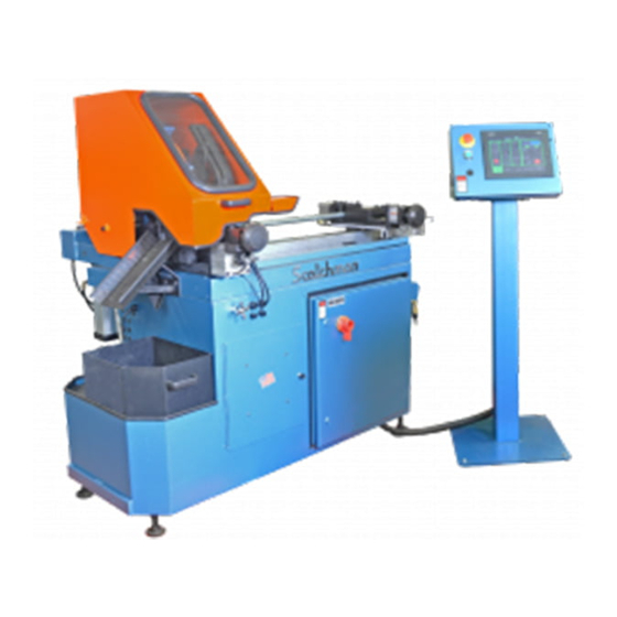
Summary of Contents for Scotchman CPO-315-HFA-NF-CNC
- Page 1 You have downloaded a manual for our MODEL CPO-315-HFA-NF-CNC COLD SAW Please read the manual before operating this saw!!
- Page 2 MODEL CPO-315-HFA-NF-CNC COLD SAW PRINTED APRIL 2023 SCOTCHMAN INDS. - 180 E US HWY 14 - PO BOX 850 - PHILIP, SD 57567 Call: 1-800-843-8844...
-
Page 3: Table Of Contents
Scheduled Maintenance Spindle Shaft Replacement Spindle Replacement (Main Vise) Seal Replacement (Main Vise) Shuttle Vise Maintenance Optional Coolant Pump Maintenance Page 2 SCOTCHMAN INDS. - 180 E US HWY 14 - PO BOX 850 - PHILIP, SD 57567 Call: 1-800-843-8844... - Page 4 Ten Foot Supply Track 11.2 Stationary Vise Regulator Shuttle Vise Regulator 11.3 12.0 COOLANTS AND LUBRICANTS 13.0 STOCK BLADES 13.0 WIRING DIAGRAMS Page 3 SCOTCHMAN INDS. - 180 E US HWY 14 - PO BOX 850 - PHILIP, SD 57567 Call: 1-800-843-8844...
-
Page 5: Introduction
1.0 INTRODUCTION The CPO-315 HFA-NF-CNC Fully Automatic Cold Saw is a high speed saw designed to cut solids, tubes, flats and other profiles in grades of nonferrous material that range from aluminum, brass, copper, synthetics and extrusions. Cold sawing is a process similar to a milling process. In most cases, this gives a finished cut that does not require any secondary machining or de-burring. - Page 8 FIGURE 1 Page 7...
- Page 10 LIFTING FORKS FIGURE 2 Page 9...
-
Page 11: Electrical Requirements
For supply lines ten feet (304 cm) or shorter, we recommend 12 gauge wire. For lines longer than ten feet (304 cm), we recommend 10 gauge wire. We do not recommend supply lines over twenty feet (609 cm) in length. CPO-315-HFA-NF-CNC (3000 RPM) MOTOR VOLTAGE FULL LOAD CURRENT HORSEPOWER 16.4... -
Page 12: Mist Coolant System
4.4 MIST COOLANT SYSTEM The coolant system on this machine is a pneumatic mist type. We recommend using only our P/N 075760, SYNCON-2 coolant in this saw. One gallon of coolant is shipped with the saw. For the best results, we recommend that it is used straight and not diluted. -
Page 14: A Recipe Setup Screen
NEVER USE A HSS BLADE ON THIS NON-FERROUS SAW NOTE: SCOTCHMAN INDUSTRIES BLADES ARE RATED FOR A MAXIMUM OF 3000 RPM. By touching the recipe field, you can name this cut job by the part number or the part name. The machine will store up to 50 cut jobs. -
Page 23: Machine Operation
6.0 MACHINE OPERATION 6.1 BLADE INSTALLATION SEE FIGURE 4A BELOW. CAUTION: THIS MACHINE IS DESIGNED TO USE CARBIDE TIPPED BLADES, ONLY. USE ONLY BLADES DESIGNED FOR THIS MACHINE. DO NOT USE BLADES DESIGNED FOR THIS MACHINE ON ANY OTHER EQUIPMENT. NEVER EXCEED THE MAXIMUM RPM OF THE BLADE. - Page 24 The CPO-315-HFA-CNC-NF saw is designed to use a maximum 12 inch (300mm) diameter blade. The arbor size is 40mm with four 10mm pins and uses a blade with 4/12/64 pin spacing. BEFORE INSTALLING THE BLADE, make sure that the power to the machine is disconnected and the air supply is turned OFF.
-
Page 25: Selecting The Proper Blade And Cutting Speed
NEVER USE A HSS BLADE ON THIS NON-FERROUS SAW Scotchman Industries offer three different 300mm (12") carbide tipped blades for this saw. They are all rated for a maximum of 3000 RPM. They have three different numbers of teeth and have two thicknesses. -
Page 26: Saw Capacities
6.3 SAW CAPACITIES SEE FIGURE 15 BELOW. Figure 15 is a chart showing the maximum capacities of this machine in various materials. RFA/ST RFA/ST CAPACITIES WITH MAXIMUM DIAMETER 90° ONLY 90° ONLY BUNDLE FEED BLADES 315 MM INCHES Ø3-1/2 Ø3 Ø3 Ø89 Ø76... -
Page 27: Material Main Vise
6.4 MATERIAL MAIN VISE SEE FIGURE 16 BELOW. FIGURE 16 Page 26... - Page 28 Proper clamping is very important and special jaws may be required for some materials. FOR MORE INFORMATION CONTACT YOUR LOCAL DEALER OR THE FACTORY. Page 27 SCOTCHMAN IND. - 180 E US HWY 14 - PO BOX 850 - PHILIP, SD 57567 Call: 1-605-859-2542...
-
Page 29: Shuttle Vise & Cylinder
FOR MORE INFORMATION ABOUT SPECIAL JAWS PLEASE CONTACT YOUR LOCAL DEALER OR THE FACTORY. Page 28 SCOTCHMAN INDS. - 180 E US HWY 14 - PO BOX 850 - PHILIP, SD 57567 Call: 1-800-843-8844... - Page 30 ADJUSTABLE STROKE CONTROL ON THE SAW HEAD • WARRANTY: TWO YEARS ON PARTS • MADE IN USA • ADJUSTABLE INDEXING FEED SPEEDS FIGURE 17 Page 29 SCOTCHMAN IND. - 180 E US HWY 14 - PO BOX 850 - PHILIP, SD 57567 Call: 1-605-859-2542...
-
Page 31: Power Down Feed
6.6 POWER DOWN FEED REFER TO FIGURE 18 BELOW. FIGURE 18 Page 30... - Page 32 CAUTION: ALWAYS DISCONNECT THE AIR SUPPLY BEFORE REMOVING THE FILLER PLUG FROM THE RESERVOIR. IF THE FILLER PLUG IS REMOVED WHILE THE MACHINE IS CONNECTED TO AIR PRESSURE, THE FLUID IN THE TANK WILL BE PURGED THROUGH THE OPENING UNDER PRESSURE. Before powering the saw, check the oil level in the reservoir (A).
-
Page 33: Material Clamping
6.7 MATERIAL CLAMPING All work pieces must be clamped securely in the vise. Any slippage of the material can result in broken or damaged blades. The material should be clamped so that the contact surface between the material and the blade is as small as possible. For this reason, when cutting flat stock material, we recommend standing it up and cutting it through the thinnest section, whenever possible. - Page 34 FIGURE 19 Page 33...
-
Page 35: Maintenance
7.0 MAINTENANCE 7.1 LUBRICATION SEE FIGURE 20 BELOW. Grease the head pivot pin (C) and the spindle shaft with a high pressure, high temperature, bearing grease daily. Apply oil to the shuttle vise guide shafts daily. Clean the chips out of the vise at least once a day, more often if needed. Apply penetrating oil to the spindle and guide pins. -
Page 36: Cutting Oils And Lubricants
7.2 CUTTING OILS AND LUBRICANTS SECTION 12.0 lists Scotchman's part numbers for cutting oils and lubricants. Using high quality lubricants and oils will greatly increase the life of this equipment. For the mister, we recommend using only our P/N 075760 - SYNCON-2 straight - not diluted. -
Page 37: Spindle Shaft Replacement
7.4 SPINDLE SHAFT REPLACEMENT REFER TO FIGURE 13 BELOW. FIGURE 21 Page 36... - Page 38 Replacing the spindle or spindle bearings on this machine is not an easy task. You should consider ordering the spindle shaft assembly (P/N 077929) which includes parts E, F, G, H, I, J, K, L and P. TO REMOVE THE SPINDLE, USE THE FOLLOWING STEPS: Remove the lock nut (C) and pull the belt sprocket (D) off the end of the shaft.
-
Page 39: Spindle Replacement (Main Vise)
7.5 SPINDLE REPLACEMENT (MAIN VISE) SEE FIGURE 22 BELOW. FIGURE 22 Page 38... -
Page 40: Seal Replacement (Main Vise)
Disconnect the machines power and the air supply. Remove the vise guard (X) and the spring (Y) and ball (HH). Remove the bolts (A & B) and the retainer (D). Remove the clevis pin (F) and remove the clevis (E) and the forks (CC). The spindle can now be removed from the machine. -
Page 41: Shuttle Vise Maintenance
7.7 SHUTTLE VISE MAINTENANCE SEE FIGURE 23 BELOW. FIGURE 23 Page 40... - Page 42 ► NOTE: Make sure everything is clean and the inside of the cylinder tube is smooth. Replace the seals and reassemble, reversing the above steps. NOTE: (34*) may or may not be included in the piston assembly. It is not needed for the CPO-315-HFA-NF-CNC machine. Page 41...
-
Page 43: Optional Coolant Pump Maintenance
7.8 OPTIONAL COOLANT PUMP MAINTENANCE (OPTINAL FLOOD COOLANT) SEE FIGURE 24 BELOW. FIGURE 24 Page 42... - Page 44 IF YOUR COOLANT PUMP IS LEAKING OR LACKS POWER, USE THE FOLLOWING STEPS: NOTE: WE RECOMMEND REPLACING THE PUMP SEAL (D) P/N 060151 ANYTIME THE PUMP IS DISMANTLED. FOR PART IDENTIFICATION, SEE THE FOLLOWING PAGE Make sure that the power to the machine is off. Remove the four bolts (J) and remove the pump from the machine.
-
Page 45: Optional Equipment
8.0 OPTIONAL EQUIPMENT 8.1 SPECIAL VISE JAWS Special vise jaws for holding thin wall round tubes, profiles and bundles are available on a made to order basis. For prices and delivery on special jaws, contact your local dealer or the factory. FOR MORE INFORMATION CONTACT YOUR LOCAL DEALER OR THE FACTORY. - Page 46 EXPLODED VIEW DETAIL VIEW 076938 13" GUIDE ASSEMBLY 029242 - 10' ROLLER CONVEYER W/LEGS FIGURE 25 Page 45...
-
Page 47: Trouble Shooting Guide
9.0 TROUBLE SHOOTING GUIDE 9.1 ELECTRICAL TROUBLE SHOOTING THE SAW MOTOR RUNS BUT DOES NOT HAVE ADEQUATE POWER. Make sure that the supply voltage and phase correspond to the saw motors voltage and phase. Disconnect the machine from the power source and check for any loose or disconnected wires. The supply lines to the machine must be of adequate size to handle the load. -
Page 48: Part Length Is Not Consistent
Always remove the back lash when installing a blade. For instructions: REFER TO SECTION 6.1. Also, check the condition of the drive pins when replacing the blade. If the drive pins are broken or worn, replace them. Any of the above problems may cause a condition known as pick-up. Pick-up is caused when the material being cut adheres itself to the blade and makes that spot on the blade wider. -
Page 49: Pneumatic System
FIGURE 26 FIGURE 26... - Page 50 THE MOST COMMON PNEUMATIC/HYDRAULIC PROBLEMS ARE: LOW LEVEL OF FLUID IN THE RESERVOIR: A sight glass is located on the back of the reservoir behind the machine. Saw head must be in the full up position to check the fluid level. Use our P/N 060520 or a SAE 10W (ISO 32) non-foaming hydraulic oil, such as Mobil DTE 10 or equivalent.
-
Page 51: Parts Lists
10.0 PARTS LISTS THE FOLLOWING SECTIONS CONTAIN THE SAW AND OPTIONAL EQUIPMENT PARTS LISTS AND DRAWINGS. FOR YOUR CONVENIENCE, ALWAYS GIVE YOUR COMPLETE SERIAL NUMBER WHEN ORDERING PARTS! 10.1 DRIVE ASSEMBLY ITEM PART # DESCRIPTION 677901 M-10 SHCS 677912 Belt Guard 077864 M-5 x 12 SHCS 077915... - Page 52 FIGURE 27 Page 51...
-
Page 53: Main Vise Assembly
10.2 MAIN VISE ASSEMBLY ITEM PART # DESCRIPTION 045308 Lower Wear Plate 221245 10 x 160mm SHCS 073458 M-6 x 10 SHCS 221240 10 x 140mm SHCS 045325 Lead Screw Cover Spring 221235 10 x 100mm SHCS 045602 045311 Clevis Guide 201160 M-8 x 60 HHCS 045312... - Page 54 FIGURE 28 Page 53...
-
Page 55: Shuttle Vise Assembly
10.3 SHUTTLE VISE ASSEMBLY ITEM QTY PART # ITEM QTY PART # DESCRIPTION DESCRIPTION 230110 M-8 x 20 DIN 7991 FSHCS 045214 Slide Plate 045211 Keeper Plate 230005 M-6 x 12 FSHCS 203212 M-10 x 30 DIN 933 HHCS 045212 Lead Screw 045668 Cyl. - Page 56 077864 M5 x 12 DIN 912 SHCS 046667 1/8" 214 O-RING 045660 Magnet 045654 PISTON SEAL KIT (44578) May or may not be included in the piston assembly. It is not needed for the CPO-315-HFA-NF-CNC machine. FIGURE 29 Page 55...
-
Page 57: Shuttle Assembly
10.4 SHUTTLE ASSEMBLY ITEM PART # DESCRIPTION 045670 T-Plate Alum 073455 M-5 x 20 DIN 912 SHCS 045669 Roller Block - Tall Bearing INA #SCE68 045233 047254 HFA Roller 045680 Sensor Target 221220 M-10 x 40 DIN 912 SHCS 045673 Spacer - Linear Drive 045671 Hold Down - Linear Rail... - Page 58 FIGURE 30 Page 57...
-
Page 59: Power Down Feed Assembly
M-10 x 25 SHCS 1/2" 90 Degree Swivel 045054 077720 Reducer Cylinder Clevis (Includes N) 077716 Sight Glass 078455 Bellow 077700 Page 58 SCOTCHMAN INDS. - 180 E US HWY 14 - PO BOX 850 - PHILIP, SD 57567 Call: 1-800-843-8844... - Page 60 FIGURE 31 Page 59 SCOTCHMAN INDS. - 180 E US HWY 14 - PO BOX 850 - PHILIP, SD 57567 Call: 1-800-843-8844...
-
Page 61: A Power Down Feed Valves
10.5A POWER DOWN FEED VALVES ITEM PART # DESCRIPTION 077746 1/4" NPT x 169 PL 077701 Baffle 3/8" NPT Plug 077777 Ninety Degree Swivel 045054 077536 Check Valve Return Line Fitting 045042 MVK6 Mounting Kit G-H-I 047535 Flow Control Valve 1/4 NPT x 1/2 PL Ninety Degree Swivel 045054 Brass 3-Way... - Page 62 FIGURE 32 Page 61...
-
Page 63: B Air Controls
10.5B AIR CONTROLS ITEM PART # DESCRIPTION Provided by Customer 077719 Shuttle Valve 077737 1/4 NPT Brass Street Elbow Brass NPT Coupler 077780 1/4" NPT Nipple 077779 Complete Filter/Regulator/Lubricator 045604 Mounting Brackets 045605 90 Degree Fitting 077738 Replacement Bowls 045609 045610 Filter Seal Kit Regulator Seal Kit... - Page 64 FIGURE 33 Page 63...
-
Page 65: Air Valve Assembly
10.6 AIR VALVE ASSEMBLY PART # DESCRIPTION ITEM 046047 DIN Connector for 060040 Fitting (5/16 PL to 1/4 NPT) 077744 Plug (3/8 NPT) 077777 ASP-3BV Breather) 045045 077740 3/8" 90 DEG Male Swivel 045650 Solenoid 24VDC 045655 Valve (Includes F) Fitting (1/4 NPT to 1/4 Hose) 677728 1/4"... - Page 66 FIGURE 34 Page 65...
-
Page 67: Blade Guard Assembly
073766 Coolant Line 046268 T Mount 026619 M-10 Tee Nut * Mister is standard equipment - Flood Coolant is optional Page 66 SCOTCHMAN INDS. - 180 E US HWY 14 - PO BOX 850 - PHILIP, SD 57567 Call: 1-800-843-8844... - Page 68 MISTER UNIT FIGURE 35 Page 67 SCOTCHMAN INDS. - 180 E US HWY 14 - PO BOX 850 - PHILIP, SD 57567 Call: 1-800-843-8844...
-
Page 69: Motor Assembly
10.8 MOTOR ASSEMBLY ITEM PART # DESCRIPTION Fan Cover EMOD 076883 073407 M5 X 6 Slot Head 076884 Fan (30mm Bore) EMOD Rear Motor Casting 30MM 077381 6206 C3 Bearing 077325 Retaining Ring 077191 KEY 6 x 4 x 30mm 077370 073326 M8 X 30 HHCS... - Page 70 FIGURE 36 Page 69...
- Page 72 FIGURE 37 Page 71...
-
Page 73: Electrical Unit-Line Circuit
10.10 ELECTRICAL UNIT - LINE CIRCUIT ITEM PART # DESCRIPTION 045483 230 Volt Power Supply 045485 Mini Circuit Breaker 045491 Manual Starter 045508 9 Amp Contactor 045512 24 Volt DC Relay 045490 Manual Starter 17-25 Amp 045481 Manual Starter 4-6.3 Amp 045537 Can Open Bus Master Module 045487... -
Page 75: Base Assembly
10.11 BASE ASSEMBLY ITEM PART # DESCRIPTION 045171 Base Cabinet Painted HFA/RFA 045415 Base Plate Casting HFA-CNC Painted 045476 Painted Lower Enclosure 045172 Front Door Painted 045257 Coolant Reservoir Screen 060150 Optional 230V Pump 060158 Optional 460V Pump 060160 Optional 575V Pump 049217 Foot Assembly (Leveling Pads) 073350... - Page 76 FIGURE 39 Page 75...
-
Page 77: Optional Coolant Pump
10.12 OPTIONAL COOLANT PUMP (OPTIONAL FLOOD COOLANT) ITEM PART # DESCRIPTION 230 Volt Coolant Pump 060150 460 Volt Coolant Pump 060158 575 Volt Coolant Pump 060160 Impeller (obsolete) 060152 Pump Oil Seal 060151 Bolt Bolt 90 Degree Elbow (Not Shown) 060080 060140 Coolant Line... - Page 78 FIGURE 40 Page 77...
-
Page 79: Stroke Control Assembly
10.13 STROKE CONTROL ASSEMBLY ITEM PART # DESCRIPTION 045253 Stroke Adjustment Plate 045249 Stroke Control Stand Stop Block 045299 045320 Stroke Sensor Mount 045330 Stop Guide 220010 M4 X 10MM BHCS 203212 M-10 x 30 HHCS 114020 3/8" Hard Washer 077796 Proximity Sensor (OLD M18 - One Used) 077795... - Page 80 FIGURE 41 Page 79...
-
Page 81: Hood Assembly
10.14 HOOD ASSEMBLY ITEM PART # DESCRIPTION 203217 M-10 x 45 HHCS 045196 Pedestal 045285 Pivot Pin 046018 Hood Handle 045464 Extension Sight Glass 045322 Sight Glass Seal 046645 201120 M-6 x 20 HHCS M-6 Nylon Loc Nut 077157 229415 M-10 x 12 x 16 Shoulder Bolt 045255 Hood... - Page 82 FIGURE 42 Page 81...
-
Page 83: Optional Equipment Parts Lists
M8 X 25 DIN9121580 12.9 SHCS 229225 M10 X 12 X 70 SB912 * 076935 - Optional Guide Assembly for older conveyors Page 82 SCOTCHMAN IND. - 180 E US HWY 14 - PO BOX 850 - PHILIP, SD 57567 Call: 1-605-859-2542... - Page 84 076938 FULLY ASSEMBLED 13" GUIDE VIEW ASSEMBLY 029242 - 10' ROLLER CONVEYER W/LEGS FIGURE 43 Page 83 SCOTCHMAN IND. - 180 E US HWY 14 - PO BOX 850 - PHILIP, SD 57567 Call: 1-605-859-2542...
-
Page 85: Stationary Vise Regulator
11.2 STATIONARY VISE REGULATOR (Option) ITEM PART # DESCRIPTION 078190 Regulator W/Gauge 677934 NF-FRL Wall Mount Bracket 077864 M5 X 12 DIN912 SHCS 077742 1/4" MALE SW X169PL 077744 1/4-5/16 NPT Straight Fitting 060501 5/16" Black Air Tube 047250 Complete Air Regulator Vise FIGURE 44 Page 84... -
Page 86: Shuttle Vise Regulator
11.3 SHUTTLE VISE REGULATOR (Option) ITEM PART # DESCRIPTION Regulator W/Gauge 078190 677934 NF-FRL Wall Mount Bracket 077864 M5 X 12 DIN912 SHCS 077746 1/4 x 90 Swivel Fittings 077744 1/4-5/16 NPT Straight Fitting 060501 5/16" Black Air Tube 077721 1/8"... -
Page 87: Coolants And Lubricants
12.0 COOLANTS AND LUBRICANTS UNIT PART DESCRIPTION 1 Gal. 075760 1 GAL. SYNCON-2 (do not dilute) 55 Gal. 075761 55 GAL. SYNCON-2 (do not dilute) 1 Qt. 075753 Air Line Lubricant 1 Gal. 075759 Air Line Lubricant Hydraulic Oil - Power Down 1 Qt. -
Page 88: Wiring Diagrams
If further assistance is needed, please call Scotchman Industries at 1-800-843-8844. Or you can go to our website at Scotchman.com for more information. Page 87 SCOTCHMAN INDS. - 180 E US HWY 14 - PO BOX 850 - PHILIP, SD 57567 Call: 1-800-843-8844... - Page 89 SCOTCHMAN HFA 230V POWER DIAGRAM PROVIDE UPSTREAM PROTECTION PER NEC TABLE 430-52 PAGE 1 230V AC 3 PHASE POWER Drawing 3757A GROUND LUG TA2/0 TIGHTENING TORQUE TORQUE 50LB.IN (2)#14-12 CU, #12-10 AL - 25"LBS #14-10 CU, #12-10 AL - 20"LBS 10awg GRN #8 AWG - 25"LBS...
- Page 90 SCOTCHMAN HFA 230V CONTROL WIRING PAGE 2 Drawing 3757A F1- 2AMP GGC2 YEL/RED YEL/BLK F2- 2AMP GGC2 YEL/RED YEL/BLK F3- 2AMP GGC2 YEL/RED F4- 2AMP GGC2 YEL/BLK YEL/RED YEL/RED BROWN BRN/RED BRN/YEL ORN/WHT ORN/BLU ORN/BLK RED/BLK YEL/BLK YEL/RED BRN/YEL BROWN...
- Page 91 SCOTCHMAN HFA 230V CONTROL WIRING PAGE 3 Drawing 3757A POWER "ON" BRN/RED BRN/YEL BROWN YEL/BLK YEL/RED YEL/WHT YEL/BLK YEL/RED YEL/WHT R2 = RUN YEL/RED YEL/RED PINK ORN/WHT YEL/RED ORN/BLU ORN/BLK M1-AUX YEL/RED YEL/BLU YEL/RED BRN/RED YEL/BLK BRN/YEL RED/BLK YEL/BLK NSYTRV42 SERIES TERMINAL SPECS.
- Page 92 SCOTCHMAN HFA 230V CONTROL WIRING PAGE 4 Drawing 3757A BRN/RED BROWN YEL/BLK YEL/RED ORN/WHT YEL/RED F5- 1/4AMP GGC1/4 ORN/BLU F6- 1/4AMP GGC1/4 ORN/BLK YEL/RED F7- 1/4AMP GGC1/4 MSP#1 YEL/BLU YEL/BLK YEL/RED RED/BLK YEL/BLK YEL/RED BRN/RED BROWN NSYTRV42 SERIES TERMINAL TERMINAL SPECS.
- Page 93 SCOTCHMAN HFA 480V POWER DIAGRAM PROVIDE UPSTREAM PROTECTION PER NEC TABLE 430-52 PAGE 1 480V AC 3 PHASE POWER Drawing 3847A GROUND LUG TA2/0 TIGHTENING TORQUE TORQUE 50LB.IN (2)#14-12 CU, #12-10 AL - 25"LBS #14-10 CU, #12-10 AL - 20"LBS 10awg GRN #8 AWG - 25"LBS...
- Page 94 SCOTCHMAN HFA 480V CONTROL WIRING PAGE 2 Drawing 3847A F1- 2AMP GGC2 YEL/RED F2- 2AMP YEL/BLK GGC2 YEL/RED F3- 2AMP YEL/BLK GGC2 YEL/RED F4- 2AMP GGC2 YEL/BLK YEL/RED YEL/RED BROWN BRN/RED BRN/YEL ORN/WHT ORN/BLU ORN/BLK RED/BLK YEL/BLK YEL/RED BRN/YEL BROWN...
- Page 95 SCOTCHMAN HFA 480V CONTROL WIRING PAGE 3 Drawing 3847A POWER "ON" BRN/RED BRN/YEL BROWN YEL/BLK YEL/RED YEL/WHT YEL/BLK YEL/WHT R1 = RUN YEL/RED YEL/RED PINK YEL/RED ORN/WHT YEL/RED ORN/BLU ORN/BLK M1-AUX YEL/RED YEL/BLU YEL/RED BRN/RED YEL/BLK BRN/YEL RED/BLK YEL/BLK YEL/RED...
- Page 96 SCOTCHMAN HFA 480V CONTROL WIRING PAGE 4 Drawing 3847A BRN/RED BROWN YEL/BLK YEL/RED ORN/WHT F5- 1/4AMP GGC1/4 ORN/BLU F6- 1/4AMP GGC1/4 ORN/BLK YEL/RED F7- 1/4AMP GGC1/4 MSP#1 YEL/BLU YEL/RED RED/BLK YEL/BLK YEL/RED BRN/RED BROWN NSYTRV42 SERIES TERMINAL TERMINAL SPECS. 600V 30A MAX.
Need help?
Do you have a question about the CPO-315-HFA-NF-CNC and is the answer not in the manual?
Questions and answers