
Subscribe to Our Youtube Channel
Related Manuals for Scotchman CPO-275


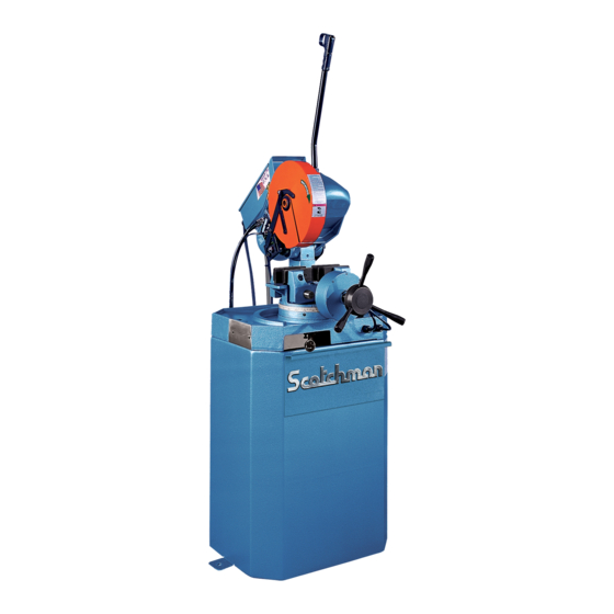
Summary of Contents for Scotchman CPO-275
- Page 1 You have downloaded a manual for our MODEL CPO-275 COLD SAW Please download our Cold Sawing Guide too. Read both the manual and guide before operating this saw!!
- Page 2 MODEL CPO-275 COLD SAW S/N B39130421 & AFTER Printed May 2021 SCOTCHMAN IND. - 180 E US HWY 14 - PO BOX 850 - PHILIP, SD 57567 Phone: 1-800-843-8844...
-
Page 3: Table Of Contents
TABLE OF CONTENTS SECTION DESCRIPTION PAGE INTRODUCTION SAFETY PRECAUTIONS WARRANTY INSTALLATION & SET-UP Physical Dimensions Machine Moving Procedures Physical Inspection Electrical Requirements Machine Start-up Guard Adjustment Coolant System MAINTENANCE & LUBRICATION Lubrication Cutting Oils & Lubricants Scheduled Maintenance Coolant Pump Maintenance MACHINE OPERATION Installing Blades Saw Capacities... - Page 4 TABLE OF CONTENTS SECTION DESCRIPTION PAGE # Special Vise Jaws Lock-Out Disconnect Switch Laser Light Pneumatic Schematic (Power Down Machines) TROUBLE SHOOTING GUIDE Electrical Trouble Shooting Breakage or Excessive Dulling of Blades Coolant System Gear Replacement PARTS LISTS Saw Head Vise Assembly Guard Assembly Motor Assembly...
-
Page 5: Introduction
1.0 INTRODUCTION The CPO-275 Cold Saw is designed to cut solids, tubes, flats and other profiles in grades of material that range from hot and cold rolled steel, annealed tool steels, stainless, aluminum, brass, copper, synthetics and extrusions. Cold sawing is a process similar to a milling process. In most cases, this, combined with the self centering vise feature, gives a finished cut that does not require any secondary machining or de-burring. -
Page 6: Warranty
This machine is top heavy and must be anchored to the floor. 3.0 WARRANTY Scotchman Industries, Inc. will, within three years of the date of purchase, replace F.O.B. the factory or refund the purchase price for any goods which are defective in materials or workmanship, provided the buyer, at the seller’s option, returns the defective goods freight and delivery prepaid to the seller, which... -
Page 7: Installation & Set-Up
4.0 INSTALLATION AND SET-UP ⌦ CAUTION: THIS SECTION DISCUSSES INSTALLATION, SET-UP AND START-UP PROCEDURES. PLEASE READ IT THOROUGHLY BEFORE OPERATING THIS MACHINE. IF YOUR MACHINE IS EQUIPPED WITH EITHER THE POWER VISE OR THE POWER DOWN FEED OPTION, READ ALL SECTIONS CONCERNING THESE OPTIONS BEFORE OPERATING THE SAW. - Page 8 FIGURE 1 Page 7...
-
Page 9: Machine Moving Procedures
4.2 MACHINE MOVING PROCEDURES SEE FIGURE 2 ON THE FOLLOWING PAGE. This machine is shipped on a pallet and can be moved to the installation location by means of a fork lift. ⌦ CAUTION: THIS MACHINE IS TOP HEAVY AND MUST BE MOVED WITH CARE, ON HARD, FLAT SURFACES ONLY. - Page 10 FIGURE 2 Page 9...
-
Page 11: Physical Inspection
4.3 PHYSICAL INSPECTION Once the machine is located, check it for any possible damage incurred in shipment. Remove the lifting eyelet and install the draw handle. ⌦ CAUTION: DO NOT USE THE LIFTING EYELET FOR ANY MACHINES OTHER THAN THIS SAW. MAKE SURE THAT THE DRAW HANDLE HAS A JAM NUT ON THE THREADS BEFORE INSTALLING IT ON THE SAW. -
Page 12: Electrical Requirements
THRU 3-8. For supply lines ten feet (303 cm) or shorter, we recommend 12 gauge wire. For lines longer than ten (303 cm), we recommend 10 gauge wire. We do not recommend supply lines over twenty feet (606cm) in length. CPO-275-LT. (30-60 RPM) MOTOR VOLTAGE FULL LOAD CURRENT... - Page 13 MANUAL OR PK W/ TRIGGER SWITCH FIGURE 3-1 Page 12...
- Page 14 PKPD W/EMERGENCY STOP FIGURE 3-2 Page 13...
- Page 15 1-PHASE MOTOR W/TRIGGER SWITCH FIGURE 3-3 Page 14...
- Page 16 1-PHASE MOTOR W/E-STOP SERIAL #'S B3431 & UP FIGURE 3-4 Page 15...
-
Page 17: Machine Start-Up
On machines equipped with either a power vise or a power down feed, the air supply must also be disconnected and locked or tagged. If your plant is not equipped with lock-out capabilities, Scotchman offers a lock-out switch as an option for this machine. If you are interested in this option, REFER TO SECTION 7.6 or contact your local dealer or the factory. -
Page 18: Guard Adjustment
4.6 GUARD ADJUSTMENT-MANUAL MACHINES SEE FIGURE 4 BELOW. FOR GUARD ADJUSTMENT PROCEDURES ON SAWS EQUIPPED WITH THE POWER DOWN FEED OPTION, REFER TO SECTION 7.2C. The proper adjustment of the blade guard on this machine is crucial to the operation of the machine and the safety of the operator. -
Page 19: Coolant System
4.7 COOLANT SYSTEM The coolant reservoir has a capacity of eight (8) gallons (30.3 liters). One gallon of coolant is shipped with the saw. For normal cutting, it should be mixed in a ratio of one part coolant to seven parts water. In conditions of heavier cutting, the ratio of water should be reduced to five parts. -
Page 20: Cutting Oils & Lubricants
5.2 CUTTING OILS AND LUBRICANTS SECTION 10.5 lists Scotchman’s parts numbers for cutting oils and lubricants. Using high quality lubricants and oils will greatly increase the life of this equipment. We recommend using only pure, synthetic, water soluble cutting oil for coolant. For the saw head, use a non-EP additive ISO-460 gear oil specified for worm gears. -
Page 21: Coolant Pump Maintenance
5.4 COOLANT PUMP MAINTENANCE FOR OLDER MODELS, REFER TO SECTION 12.0. IF YOUR COOLANT PUMP IS LEAKING OR LACKS POWER, USE THE FOLLOWING STEPS. We recommend replacing the pump seal kit anytime that the pump is dismantled. FOR PART NUMBER IDENTIFICATION, REFER TO SECTION 9.6. Make sure that the power to the machine is off. - Page 22 FIGURE 5A Page 21...
-
Page 23: Machine Operation
6.0 MACHINE OPERATION 6.1 INSTALLING BLADES - MANUAL MACHINES SEE FIGURE 6 BELOW. FOR INSTALLING BLADES ON MACHINES EQUIPPED WITH THE POWER DOWN FEED OPTION, REFER TO SECTION 7.2D. FIGURE 6 Page 22... - Page 24 DO NOT MODIFY ANY BLADE TO FIT THIS MACHINE. DO NOT USE BLADES DESIGNED FOR THIS MACHINE ON ANY OTHER EQUIPMENT. The CPO-275 saw is designed to use a maximum 10-3/4 inch (275mm) diameter blade. The arbor size is 32mm with two 8mm pins spaced at 45mm.
-
Page 25: Saw Capacities
CPO - 275 #060330 03/21 90° 45° CAPACITIES WITH MAXIMUM DIAMETER BLADES 275 MM INCHES Ø3-3/8 Ø2 Ø86 Ø51 INCHES 3 X 3 2 X 2 76 X 76 51 X 51 INCHES 3 X 3 2 X 2 76 X 76 51 X 51 INCHES 3 X 3... -
Page 26: Selecting The Proper Blade & Cutting Speed
6.3 SELECTING THE PROPER BLADE AND CUTTING SPEED In cold sawing, there is no such thing as a general purpose blade. To achieve the best results from your saw, proper blade selection is important. Each saw is shipped with a pitch (number of teeth) calculator, which will help to determine the proper blade for your application. -
Page 27: Material Clamping
6.4 MATERIAL CLAMPING All work pieces must be clamped securely in the vise. Any slippage of the material can result in broken or damaged blades. The material should be clamped so that the contact surface between the material and the blade is as small as possible. For this reason, when cutting flat stock material, we recommend standing it up and cutting it through the thinnest section, whenever possible. - Page 28 FIGURE 8 FIGURE 9 Page 27...
-
Page 29: Miter Locking Device
6.5 MITER LOCKING DEVICE SEE FIGURE 10 ON THE FOLLOWING PAGE. All models manufactured for domestic sales are equipped with a miter locking device which allows quick set-up for mitering at 45 degrees, left and right, and 90 degrees for straight cutting. A miter locking device is available as an option for models manufactured for international sales. - Page 30 FIGURE 10 Page 29...
-
Page 31: Optional Equipment
7.0 OPTIONAL EQUIPMENT 7.1 POWER VISE The power vise is an option that is normally ordered with the saw. It is not recommended as a retro-fit in the field. The power vise allows automatic clamping of the material, which improves productivity and reduces operator fatigue. - Page 32 TO ADJUST THE VISE TO THE SIZE OF MATERIAL BEING CUT: Release the locking collar (D) on the vise spindle. The vise spindle is left hand threaded and the locking collar must be turned clockwise to release it. Open the vise, using the positioning handle (E), and place the material in the vise. Crank the vise closed to within approximately 1/8 of an inch (3mm) from the material and relock the locking collar (D).
-
Page 33: B Replacing The Spindle In The Air Vise
7.1B REPLACING THE SPINDLE IN THE AIR VISE SEE FIGURE 12 ON THE FOLLOWING PAGE. Disconnect the machine’s power and air supply. Remove the air lines (A) from the front of the cylinder. Remove the support block (B), the bolts (C) and the spacer (I) from the base of the vise. Remove the guide pins (D) out through the back of the vise. -
Page 34: C Replacing The Seals In The Air Vise
7.1C REPLACING THE SEALS IN THE AIR VISE SEE FIGURE 13 ON THE FOLLOWING PAGE. Open the vise to its full open position. Disconnect the air lines from the cylinder. Remove the jam nut (G), the hand wheel (B) and the locking collar (C) from the front of the spindle. -
Page 35: Power Down Feed
7.2 POWER DOWN FEED The power down feed option, used in conjunction with the power vise option, changes a manual saw into a semi-automatic saw. These options will increase productivity and reduce operator fatigue. The power down feed option cannot be retrofit to machines with serial number 11940491 and prior in the field. This option can be used on machines with or without the power vise option. - Page 36 FIGURE 14 Page 35...
-
Page 37: B Stroke Control Adjustment-Power Down Feed
7.2B STROKE CONTROL ADJUSTMENT (POWER DOWN FEED) SEE FIGURE 15 ON THE FOLLOWING PAGE. Before powering the machine, the up and down strokes of the saw head must be set. The stroke is set by the collars (A & B) on the shaft (C). TO SET THE STROKE: Without powering the saw, cycle the head down by depressing the foot switch, with the HI-Low switch in the OFF position. - Page 38 FIGURE 15 Page 37...
-
Page 39: C Guard Adjustment-Power Down Feed
7.2C GUARD ADJUSTMENT (POWER DOWN FEED) SEE FIGURE 16 ON THE FOLLOWING PAGE. ⌦ CAUTION: THE GUARD MUST BE ADJUSTED EVERY TIME THAT THE STROKE OF THE MACHINE IS ADJUSTED. TO ADJUST THE GUARD: Before adjusting the guard, set the up and down stroke of the machine by following the instructions in SECTION 7.2. - Page 40 FIGURE 16 Page 39...
-
Page 41: D Installing Blades-Power Down Feed
7.2D INSTALLING BLADES (POWER DOWN FEED) SEE FIGURE 17 ON THE FOLLOWING PAGE. ⌦ CAUTION: USE ONLY HIGH SPEED STEEL BLADES DESIGNED FOR THIS MACHINE. DO NOT MODIFY ANY BLADE TO FIT THIS MACHINE. DO NOT USE BLADES DESIGNED FOR THIS MACHINE ON ANY OTHER EQUIPMENT. The CPO-350 saw is designed to use a maximum 14 inch (350mm) diameter blade. - Page 42 FIGURE 17 Page 41...
-
Page 43: E Power Down Feed Troubleshooting
7.2E POWER DOWN FEED TROUBLESHOOTING THE HEAD FEEDS DOWN FULL SPEED WITH THE FLOW CONTROL (D) TURNED OFF. Bad check valve (V): Clean or replace it. THE HEAD FEEDS FAST WITH NO CONTROL, HEAD BANGING UP, LOW OIL LEVEL. Add oil (hydraulic oil). THE HEAD STOPS AND DOES NOT FEED THROUGH THE MATERIAL. - Page 44 FIGURE 18 Page 43...
-
Page 45: Material Supply Tracks
7.3 MATERIAL SUPPLY TRACKS A ten foot roller supply track, that can be bolted to the input side of the saw to support longer pieces of material, is an available option for this saw. The supply tracks can also be bolted end to end, to supply longer tracks, if needed. - Page 46 FIGURE 19 Page 45...
-
Page 47: Discharge Tracks With Scale
7.4 DISCHARGE TRACKS WITH SCALES Roller discharge tracks equipped with either a right or left hand quick-loc are available in two lengths: 60" and 120" (122 & 303 CM). The discharge tracks mount to the machine in place of the 30 inch (76 CM) stop that was provided with the machine. - Page 48 FIGURE 20 Page 47...
-
Page 49: Special Vise Jaws
7.5 SPECIAL VISE JAWS Special vise jaws for holding square tubing, rectangular tubing and angle iron are stock items. Jaws for holding thin wall round tubes, profiles and bundles are available on a made-to-order basis. For prices and delivery on special jaws, contact your local dealer or the factory. 7.6 LOCK-OUT DISCONNECT SWITCH A lock-out disconnect switch is available for this machine if your plant is not equipped with lock-out capabilities. - Page 50 FIGURE 20A Page 49...
-
Page 51: Trouble Shooting Guide
8.0 TROUBLE SHOOTING GUIDE 8.1 ELECTRICAL TROUBLE SHOOTING 1. THE MOTOR WILL NOT RUN: Some models have a lock-out switch in the base of the saw. If your saw has this option, make sure that it is in the ON position. On manual and power vise machines, the Hi-Low switch must be in either the Hi or the Low position for the trigger switch to work. -
Page 52: Breakage Or Excessive Dulling Of Blades
8.2 BREAKAGE OR EXCESSIVE DULLING OF BLADES Select the proper blade and spindle speed for the material being cut. For recommendations, REFER TO SECTION 6.3. Always break in the blade before you start normal cutting. Do not apply excessive down pressure on the workpiece. Excessive down pressure will cause the teeth to remove too large of a chip, resulting in premature dulling or breakage. -
Page 53: Coolant System
8.3 COOLANT SYSTEM IF COOLANT WILL NOT FLOW: Check the wiring connections to the pump and make sure that the pump is running in the right direction. The pump has an arrow in the casting to indicate the direction. Check the level of the coolant in the reservoir. If the level is less than 3 inches, the fluid will not flow. -
Page 54: Gear Replacement
8.4 GEAR REPLACEMENT SEE FIGURE 21 BELOW. Remove the drain plug (A) from the head casting and allow the fluid to drain. Remove the motor from the head. Remove the three bolts (B) from the bearing housing (C) through the access holes in the guard. Remove the spindle shaft (D) with a slide hammer. -
Page 55: Parts Lists
9.0 PARTS LISTS 9.1 SAW HEAD ITEM PART # DESCRIPTION 075080 Key 7 x 8 x 32mm 077151 Spindle Shaft 077143 Spindle Cap 075075 Seal 077146 Gasket 075076 Roller Bearing 077147 Spacer Ring 077148 Spacer Bushing 077149 Worm Gear (Bronze) 075081 Snap Ring 077150... - Page 56 073108 M-8 Lock Washer 221120 M-8 x 25 SHCS 080193 M-8 Blade Allen Wrench (Not pictured) 077630 Vent 073692 Eye Bolt (Not pictured) 077107 Complete Head Assembly 073106 M-6 Lock Washers FIGURE 22 Page 55...
-
Page 57: Vise Assembly
9.2 VISE ASSEMBLY ITEM PART # DESCRIPTION 221215 M-10 x 35 SHCS 077128 Cast Grip Cheek (Rear) 077119 Vise Jaw (Right) 208012 M-10 Hex Nut 077120 Guide Shaft 077310 Seal 077132 275 Vise Base-Sales 077100 Dowel Pin 077133 Screw End 077136 Pressure Plate 677879... - Page 58 FIGURE 23 Page 57...
-
Page 59: Guard Assembly
9.3 GUARD ASSEMBLY ITEM PART # DESCRIPTION Complete Guard Assembly 070000 221120 M-8 x 25 SHCS 077164 Spacer Ring (Thick) Hinged Cap (Front) Spacer Ring (Thin) 077165 Hinged Cap (Rear) 077166 Bushing 077167 Snap Ring 077160 M-8 Plastic Washer 077163 Coupling Rod 077162 Rivet... - Page 60 FIGURE 24 Page 59...
-
Page 61: Motor Assembly
9.4 MOTOR ASSEMBLY ITEM PART # DESCRIPTION 076555 Fan Cover 076890 Fan Cover - 1 PH 073444 M4 X 10 DIN912 SHCS 076895 275 Fan Blade EMOD 076891 Fan - 1 PH End Casting 077194 075050 Distance Ring 075049 Rear Bearing (6205 Z) 076369 Key 6 x 6 x 15mm 073326... - Page 62 078000 60 RPM/230 Volt 1 Phase/T-S 078001 60 RPM/230 Volt 1 Phase/E-S FIGURE 25 Page 61...
-
Page 63: Electrical
9.5 ELECTRICAL UNIT ITEM PART # DESCRIPTION 060094 Switch Box and Lid Sales Included with Item A 221002 M-4 x 12 SHCS 060071 Contactor-24 Volt (S/N Needed) 077881 220 Volt Contactor (Used from 1990-1996) 460 Volt Contactor (Used from 1990-1996) 077882 078456 M4/6 TERMINAL BLOCK... - Page 64 DANGER ELECTRICAL HAZARD Turn off power and lock out before servicing. FIGURE 26 Page 63...
-
Page 65: Coolant System & Base
9.6 COOLANT PUMP FOR OLDER MODELS, REFER TO SECTION 12.3. ITEM PART # DESCRIPTION 060165 220V 1PH Pump 060205 220V 1PH Pump Assembly 060150 230V 3PH Pump 060200 230V 3PH Pump Assembly 060158 460V 3PH Pump 060201 460V 3PH Pump Assembly 060160 575V Coolant Pump Assemblies include A, G &... - Page 66 FIGURE 27 Page 65...
-
Page 67: Cast Base & Pedestal
9.7 CAST BASE AND PEDESTAL ITEM PART # DESCRIPTION 077111 Pedestal 077113 Base Casting 660535 Base Casting Power Vise 203210 M-8 x 25 SHCS 077225 Miter Lock Mount 077227 Spring 077226 Release Handle 077228 073660 M-8 x 12 HHCS 073420 M-8 x 25 SHCS 077212 Upper Spring Mount... - Page 68 FIGURE 28 Page 67...
-
Page 69: Material Stop 30 Inch (76 Cm)
9.8 CAST SAW BASE CABINET ITEM PART # DESCRIPTION 760115 CPO Base Cabinet 760114 CPO Chip Drawer 760115.8 Pump Mounting Bracket 073420 M-8 x 16 DIN912 SHCS 215013 M-8 Greer Nut 060170 1/8” Clearflex Plastic 060175 Rear Cover Strap 154003 Alum Rivet Page 68... - Page 70 FIGURE 29 Page 69...
-
Page 71: Optional Equipment Parts Lists
10.0 OPTIONAL EQUIPMENT PARTS LISTS 10.1 POWER VISE ASSEMBLY ITEM PART # DESCRIPTION 077415 Acme Nut 077414 Cast Grip Cheeks 221015 M-6 x 80 SHCS 077422 Screw Spindle 060204 Cylinder Housing 077417 O-Ring 077416 O-Ring 077411 Piston 077418 Roll Pin 060450 Cylinder Cover 077419... - Page 72 077409 Lock Ring 060270 Covering Cap 077310 Seal 077412 Complete Air Cylinder 076371 Cylinder Seal Kit (Includes F, G & K) 677878 Complete Air Vise FIGURE 30 Page 71...
-
Page 73: Power Down Feed Assembly
10.2 POWER DOWN FEED ASSEMBLY ITEM PART # DESCRIPTION 065010 Bracket Assembly (Upper) 073420 M-8 x 16 SHCS 077211 Return Spring 078524 Cylinder Bracket 065025 Bracket Assembly (Lower) 140415 1/2" Clevis Pin 078520 Stroke Adjustment Rod 123120 1/8" Cotter Pin 078518 Stroke Adjustment Stop (Upper) 078518... - Page 74 FIGURE 31 Page 73...
-
Page 75: A Power Down Feed Controls
10.2A POWER DOWN FEED CONTROLS (SER. #'S B31071003 & UP) ITEM PART # DESCRIPTION 077736 Valve Mount Assembly 077183 Cord Connector 077738 90 Degree Swivel x 169 PL 047535 Flow Control Valve 077746 1/4" NPT x 1/4" Street PL 078190 Regulator 077770 1/4"... - Page 76 FIGURE 32 Page 75...
-
Page 77: B Power Down Feed Electric Controls
10.2B POWER DOWN FEED ELECTRICAL CONTROLS (SERIAL #'S B31071003 & UP) ITEM PART # DESCRIPTION 075250 Enclosure 077183 Cord Grip 075205 Mounting Plate 075210 Mounting Strip 073440 M-4 x 6 SHCS 078104 End Bracket 078456 M-4 x 6 Terminal Block 078457 Jumper 060044... - Page 78 FIGURE 33 Page 77...
-
Page 79: C Guard Assembly (Power Down Feed)
10.2C GUARD ASSEMBLY (POWER DOWN FEED) ITEM PART # DESCRIPTION 275PD Guard Sales 070005 221120 M8 x 25 SHCS Movable Guard 077167 Snap Ring 077202 Spacer Nylon 078516 PD Guard Stop 073691 M6 x 12 Knob 077165 060140 9/16 x 85” Coolant Line 077154 Hose Barb 077155... - Page 80 FIGURE 34 Page 79...
-
Page 81: Foot (303 Cm) Supply Track
10.3 TEN FOOT (304 CM) SUPPLY TRACK ITEM PART # DESCRIPTION 029243 Conveyor Assembly 029244 Leg Assembly 204230 M-10 x 100 HHCS 221210 M-10 x 25 HHCS 029245 Roller 076938 Optional Guide Assembly 229225 M-10 x 70 Shoulder Bolt 043003 Guide Roller 214012 M-10 Washer... - Page 82 FIGURE 35 Page 81...
-
Page 83: Discharge Tracks (48, 84 & 120 Inch)
10.4 DISCHARGE TRACKS W/QUICK-LOC (60 & 120 INCH) ITEM PART # DESCRIPTION COMMON PARTS 029244 Leg Assembly 029241 60" Roller Conveyor 029243 120" Roller Conveyor 029114 Quick-Loc Arm Ext. 029175 Rail Mounting Bracket 130107 5/16 x 18 x FSHCS 130212 3/8 x 16 x 1-1/4 C-Bolt 029272 Mounting Bracket... - Page 84 FIGURE 36 Page 83...
-
Page 85: Cutting Coolants & Oils
10.5 COOLANTS AND LUBRICANTS ITEM PART # DESCRIPTION 1 Gal. 075751 Synthetic Coolant Synthetic Coolant 5 Gal. 075752 55 Gal. 075754 Synthetic Coolant 1 Gal. 075756 Special Mix Coolant 5 Gal. 075757 Special Mix Coolant 1 Qt. 075753 Air Line Lubricant 1 Gal. - Page 86 FIGURE 37 Page 85...
-
Page 87: Laser Light
10.7 LASER LIGHT ITEM PART # DESCRIPTION 065002 Laser 065000 Complete Laser Assembly 065003 Laser Cover 065005 Laser Mounting Bracket 065007 Laser Pivot 214012 M-10 Washer 201200 M-10 x 12 HHCS 221007 M-4 x 8 SHCS 046094 Medium Wire Clip Laser Transformer 012336 Toggle Switch... - Page 88 FIGURE 38 Page 87...
- Page 89 10.8 MATERIAL STOP 30 INCH (72 CM) ITEM PART # DESCRIPTION 677436 Stop Clamp (Includes D) 060315 Stop Shaft 060310 Shaft 073460 M-10 x 16 SHCS 076930 Complete Ass’y (A, B, C, F & G) 080193 M-8 Wrench (Not Shown) 210016 M-16 Jam Nut Page 88...
- Page 90 FIGURE 39 Page 89...
-
Page 91: Stock Blades
11.0 STOCK BLADES ITEM PART # DESCRIPTION 074300 90 Tooth 10 Inch (250mm) Dia. 074304 100 Tooth 10 Inch (250mm) Dia. 120 Tooth 10 Inch (250mm) Dia. 074302 074306 150 Tooth 10 Inch (250mm) Dia. 180 Tooth 10 Inch (250mm) Dia. 074305 074307 240 Tooth 10 Inch (250mm) Dia. - Page 92 Style 2 Style 2A Style 3 Notch Grind FIGURE 40 THERE ARE FOUR STYLES OF BLADES AVAILABLE: STYLE 2: Has a round back tooth with a square face and top. This style is designed for thin wall, nonferrous tubes, plastics and synthetics. STYLE 2A: Is an alternate top bevel grind.
- Page 93 The Worlds Best Cold Saws & Ironworkers Proudly Made In America www.scotchman.com Scotchman Ind. - 180 E US Hwy 14 - Philip, SD 57567 1-605-859-2542 - www.scotchman.com 10/8/20...
- Page 105 16° - 18° Hook Angle is Standard and is often referred to as "Rake" or "Rake Angle" DATE: SCALE: PART NAME: TOLERANCE (UNLESS SPECIFIED) Cold Saw Blade The Worlds Best Cold Saws & Ironworkers Scotchman Inds. Scotchman Inds. 5/12/16 None .0 = +/-.02 (.5mm) 180 E US Hwy 14 Tooth Geometry Proudly Made In America .00 = +/-.01 (.25mm)
- Page 106 .050 Wall Thickness DATE: SCALE: PART NAME: TOLERANCE (UNLESS SPECIFIED) The Worlds Best Cold Saws & Ironworkers Scotchman Inds. Selecting the Proper Scotchman Inds. 5/12/16 None .0 = +/-.02 (.5mm) 180 E US Hwy 14 Cold Saw Blade Proudly Made In America .00 = +/-.01 (.25mm)
- Page 107 Triple Chip and Alternate Grinds are by far the most common. Power 2000 Blades have the Notch Grind & Titanium Coating. DATE: SCALE: PART NAME: TOLERANCE (UNLESS SPECIFIED) Scotchman Inds. The Worlds Best Cold Saws & Ironworkers Selecting the Proper Scotchman Inds. 5/12/16 None .0 = +/-.02 (.5mm)
Need help?
Do you have a question about the CPO-275 and is the answer not in the manual?
Questions and answers