Table of Contents
Advertisement
Advertisement
Table of Contents

Related Manuals for Scotchman SUP-600-NF


Summary of Contents for Scotchman SUP-600-NF
- Page 1 SUP-600-NF COLD SAW PRINTED AUGUST 2015...
- Page 2 PAGE 2...
-
Page 3: Table Of Contents
TABLE OF CONTENTS SECTION DESCRIPTION PAGE # INTRODUCTION Legislation Applicable to Planning and Construction GENERAL MACHINE INFORMATION Machine Identification Data Technical Data Dimensions of the Machine Cutting Capacity Electrical Data Noise Level INDICATIONS REGARDING TRANSPORT AND STORAGE INSTRUCTIONS FOR ANCHORING AND SERVICE START-UP Anchoring Instructions Pressure Regulator Instructions Regarding Blade Installation... -
Page 4: Introduction
INTRODUCTION This instruction manual has been made in compliance with Legislation according to the Machine directive 2006/42/CEE and its subsequent amendments. The instruction manual represents an integral part of the machine. It must be consulted before, during and after the machine is put into service, as well as whenever it is considered necessary, thereby respecting its content in each and every one of its parts. -
Page 5: General Machine Information
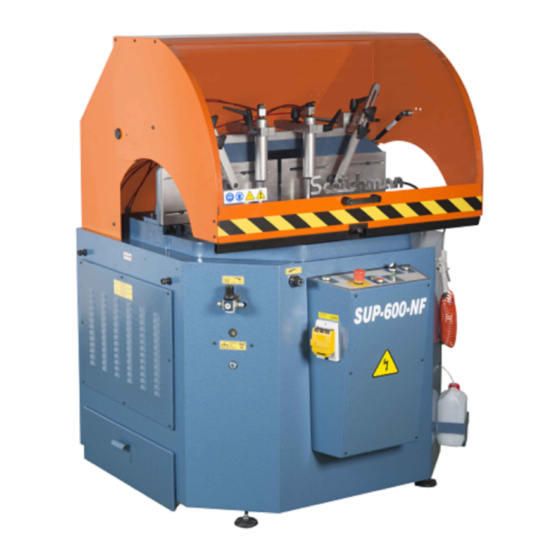
2.0 GENERAL INFORMATION 2.1 Machine Identification Data Model---------------------------- SUP-600-NF Serial number------------------ Manufacturing year----------- NOTE: IN ORDER TO REQUEST SPARE PARTS, WHETHER COVERED BY THE WARRANTY OR NOT, ALWAYS INDICATE THE MODEL AND SERIAL NUMBER OF THE MACHINE, AS WELL AS THE NAME OF THE PART AND THE PART NUMBER THAT APPEAR IN THE LAST CHAPTER OF THE PARTS EXPLODED VIEWS. -
Page 6: Dimensions Of The Machine
2.3 Dimensions of the Machine 1 636mm 1636mm 1052mm 911mm 850mm 770mm 905mm 934mm 1050mm ANCHO MAX: 1249mm 1301mm 2.4 Cutting Capacity TURRET 90º 45º 22.5º PAGE 6... -
Page 7: Electrical Data
2.5 Electrical Data Power Supply Motor Power Total Consumption 230 V Three phase 4 kW/5.3 HP 12 A 460 V Three phase 4 kW/5.3 HP 2.6 Noise Level At a distance of 2' RUNNING OFF-LOAD 80dB (A) MACHINING A 70 X 50 PROFILE 120 dB (A) Ü... -
Page 8: Instructions For Anchoring And Service Start-Up
INSTRUCTIONS FOR ANCHORING/ SERVICE START-UP 4.1 Anchoring Instructions Ensure that the machine has not suffered any damage during transport by making an initial visual inspection. If damage is observed, advise the carrier immediately. The machine must be installed on a firm surface that is as level as possible, in order to reduce vibrations during operation and so that it operates within the parameters established by the manufacturer. -
Page 9: Instructions Regarding Blade Installation
4.3 Installing The Blade Rotate the blade to 22.5°, toward the left side, and lock it in this position. Loosen the blade with the bar and wrench sent with the machine. Place the new blade on the spindle and align it with the screw mounted in the spindle. -
Page 10: Instructions For Use
5. INSTRUCTIONS FOR USE 5.1 Proper and Improper Use This is a semiautomatic cut-off machine especially designed for cutting aluminum profiles. The use of the machine for cutting other materials is hereby prohibited. Such use may cause damage to the machine and put the health and safety of the worker at risk. Ü... -
Page 11: Instructions For The Adjustment Of The Digital Degrees
5.3 Adjusting the Digital Degrees To zero the digital readpot, press the (F) and (Set) keys. To change the way of reading of incremental to absolute, press (Inc/Abs). ATTENTION: Care must be used when cleaning the screen. The surface is plastic and is easily scratched. -
Page 12: Recommendations And Maintenance
6.0 RECOMMENDATIONS AND MAINTENANCE 6.1 Type and Frequency of Inspections The operator's knowledge of the machine is one of the best ways of daily control of any possible problem. If any failure is detected, work must be stopped and qualified personnel must be informed immediately. NOTE: Always clean the machine and the work area at the end of the work day. -
Page 13: Qualified Personnel For Maintenance And Repair Work
6.2 Qualified Personnel for Maintenance and Repair Work All repairs shall be made exclusively by qualified personnel. Always use original replacement parts. If not, the machine may be damaged or the user may be injured. 6.3 Manufacturer's Recommendations þ In the event that the machine is broken down or the saw blades must be replaced, place a padlock on the protection switch and place the keys under the care of qualified personnel. -
Page 14: Drawings And Schematics
7.0 DRAWINGS & SCHEMATICS 7.1 General Schematic ITEM PART # DESCRIPTION Æ45 Pneumatic Hold-Down Clamp 2050000202 Horizontal Clamps Æ Ext 40 N00PT14050 2040000482 Angle Lock N000000018 Advance Regulator 3/8" Blow Air Duster 2-Position Selector E0000000030 Green Indicator Saw Blade On-Off Emergency Green Vertical Alignment Button General Switch... - Page 15 PAGE 15...
-
Page 16: Power Circuit
7.2 Power Circuit ITEM PART # DESCRIPTION E000000004 Main Switch 10A E000000005 Main Switch 16A E000000034 Contactor TKC9 24V 50/60HZ 21690460M3 4KW Motor III 460V C/Freno 21690220M3 4KW Motor III 230V C/Freno E000046014 Transformer 50VA - 460/230//24V E000000024 Fuse 2A E000000G44 Emergency (NC) Green Indicator Æ... -
Page 17: A Switching Power Circuit
7.2A Switching Power Circuit ITEM PART # DESCRIPTION E000000G71 2-Position Selector E00000BD25 Shield End-of-Travel Stop E000000015 End-of-Travel M-12 E000000G75 Saw Blade On-Off E000000G50 Green Push-Button NO N000000A34 5/2 Ways Mono. Electrovalve N000000069 High + Low Pressure Pneumatic E000000034 TKC9Contactor 24V 50/60HZ ECNKT50RQD Magnetic Sensor Magi 6.2 E000000095... -
Page 18: Operating Controls
7.3 Operating Controls Emergency button with interlock. Green indicator light; power supplied to the machine. Hold down clamp selector. Saw blade on-off; On, green colored symbol, I. Off, red O. Push buttons, for raising the saw blade. Auto-manual selector for the pneumatic protective shield operation; optional. PAGE 18... - Page 19 THIS PAGE LEFT BLANK INTENTIONALLY. PAGE 19...
-
Page 20: Pneumatic Schematic
7.4 Pneumatic Schematic ITEM PART # DESCRIPTION Line N000000A17 F + R + L 1/4" N000000A34 5/2 Ways Mono. Electrovalve N000000069 High + Low Pressure Neumatic N000000038 Quick Exhaust Valve 1/8" N000000030 Pressure Regulator 1/4" Clamping Cylinder Æ Ext 40 x 320 N02PT14050 2K20000281 Mini Ball Valve 1/8"... - Page 21 TL-600-PLUS AUTOMATIC SHIELD LINEA PAGE 21...
-
Page 22: Cast Iron Table & Disc Assembly (Exploded View)
7.5 Cast Iron Table & Disc Assembly (Exploded View) ITEM PART # DESCRIPTION TD79910616 DIN7991 M-6 x 16 Screw Blade Groove 2352000171 Degrees Turn Lever B0000000H2 Handle Tristar M-10 TD91310070 DIN913 M-10 x 70 Screw Brake of Degrees Rocker Support DIN128 Æ12 Washer TD12800012 TD91212050... - Page 23 PAGE 23...
-
Page 24: Rocker Assembly (Exploded View)
7.6 Rocker Assembly (Exploded View) ITEM PART # DESCRIPTION TD93400030 DIN934 M-30 Nut 2040000042 Blade Washer Widia Blade Æ600 x Æ50 x 5 205DW60032 TD91208012 DIN912 M-8 x 12 Screw 2040000172 4206 Bearing Æ 30 Shaft 2040000102 2070000012 Lubricator 1/8" TD91206010 DIN912 M-6 x 10 Screw TD91208016... - Page 25 PAGE 25...
-
Page 26: Turret Assembly (Exploded View)
7.7 Turret Assembly (Exploded View) ITEM PART # DESCRIPTION Lock Guide Plate Turret Cotter Iron Turret TD91210030 DIN912 M-10 x 30 Screw B000091040 M-10 x 40 Lever TD91206016 DIN912 M-6 x 16 Screw TD912208012 DIN912 M-8 x 12 Screw Clamps Aluminum Guide 2350000131 Nylon Cleat Black M-10 Flat Nut M-12... - Page 27 PAGE 27...
-
Page 28: Sheet Metal Base (Exploded View)
7.8 Sheet Metal Base (Exploded View) ITEM PART # DESCRIPTION Left Door T173800620 ISO7380 M-6 x 20 Screw TD93400014 D934 M-14 Nut Connect Æ6-Æ6 2050000262 Back Door T173800620 ISO7380 M-6 x 20 Screw E000000022 Three Phase Base Oleoneumatid Conv. N00RHM1412 Reduction 1/2M - 1/4H Male Stud Elbow 1/4 - Æ8 N000CC1408... - Page 29 Æ40 Manometer N000000020 N0000TA012 Metal Stopper Gas 3/8" N0000TA012 Metal Stopper Gas 3/8" TD91206016 D912 M-6 x 16 Screw Male Stud Elbow 1/4 - Æ6 N000CC1406 Booth of Shaving T173800620 ISO7380 M-6 x 20 Screw Wheel Æ30 216000030P Left Door 10 11 12 14 15 16 17 PAGE 29...
-
Page 30: Protective Shield (Exploded View)
7.9 Protective Shield (Exploded View) ITEM PART # DESCRIPTION T173800610 ISO-7380 M-6 x 10 Screw Left Protective Shield TD93400006 DIN934 M-6 Nut B000000015 M-8 Handle 2160000142 1090x670x3 Methecrylite Front Closing 204000R452 Swivel Joint Above Closing 2160000300 Shock Abso. R300 - L125 - 250N Ball Screw Æ10 M-8 20400TB452 Separator M-8 x 20 Æ25mm... - Page 31 PAGE 31...
-
Page 32: Optional Equipment
8.0 OPTIONAL EQUIPMENT 8.1 Pneumatic Protective Shield ITEM PART # DESCRIPTION DIN-471 Æ12 ISO-40 Pin TD93400006 DIN-934 M-6 Nut T173800620 ISO-7380 M-6 x 20 Screw CN000904059 90° Swivel Flange ISO-40 TD91208025 DIN-912 M-8 x 25 Screw CN000004059 ISO-40 Swivel Flange DIN-471 Æ12 CN00040158 ISO 40 x 158 Cylinder... - Page 33 PAGE 33...
-
Page 34: Digital Control Of The Cut Height
8.2 Digital Control of the Cut Height In order to change the cut height, press PRESET to edit the height. To change the value with the key, Press SET + Up + RESET. Press PRESET to finish the edition. SW ITCHING PO WE R CIRCUIT 12 4 12 4 12 4... -
Page 35: Lubetool Micro-Lubrication (Optional)
8.3 Lubetool Micro-Lubricatin (Optional) 66 I MPULS OS x MINUT O 37 IMP ULSOS xM INUTO 21 IMPULSOS xMI NUTO 13 I MPULS OS x MINUTO S TROKE S E VERY MINUTE STROKES EV ERY MI NUTE STROK ES EVE RY MI NUTE S TROKE S E VERY MINUTE 10 I MPULS OS x MINUT O 6 IM PULS OS x MINUTO... - Page 36 PAGE 36...
Need help?
Do you have a question about the SUP-600-NF and is the answer not in the manual?
Questions and answers