
Subscribe to Our Youtube Channel
Related Manuals for Scotchman SUP-600-NF


Summary of Contents for Scotchman SUP-600-NF
- Page 1 You have downloaded a manual for our MODEL SUP-600-NF PRECISION MITER UP-CUT NON-FERROUS SAW...
- Page 2 MODEL SUP-600-NF COLD SAW PRINTED MAY 2021 SCOTCHMAN INDS. - 180 E US HWY 14 - PO BOX 850 - PHILIP, SD 57567 Call: 1-605-859-2542...
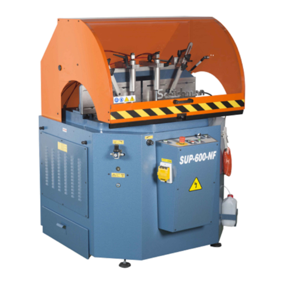
- Page 3 SUP-600 NF SAW FIGURE 1 Page 2...
- Page 4 SU-280-G BAND SAW 66 to 176 TON PRESSPRO HYDRAULIC PRESSES SCOTCHMAN INDS. - 180 E US HWY 14 - PO BOX 850 - PHILIP, SD 57567 Call Toll Free in USA: (800) 843-8844 Call Direct: 1 -605-859-2542 Fax: (800)-843-5545 Email: info@scotchman.com...
-
Page 5: Table Of Contents
TABLE OF CONTENTS SECTION DESCRIPTION PAGE # INTRODUCTION Warranty GENERAL MACHINE INFORMATION Machine Identification Data Technical Data Dimensions of the Machine Cutting Capacity Electrical Data Noise Level INSTRUCTIONS REGARDING TRANSPORT AND STORAGE INSTRUCTIONS FOR ANCHORING AND SERVICE START-UP Anchoring Instructions Power Supply Connection Pressure Regulator Installing the Blade... -
Page 6: Introduction
1.1 Warranty Scotchman Industries, Inc. will, within three years of the date of purchase, replace F.O.B. the factory or refund the purchase price for any goods which are defective in materials or workmanship, provided the buyer, at the seller’s option, returns the defective goods freight and delivery prepaid to the seller, which shall be the buyer’s sole and exclusive remedy for defective goods. -
Page 7: General Machine Information
2.0 GENERAL MACHINE INFORMATION 2.1 Machine Identification Data MODEL - SUP-600-NF SERIAL NUMBER YEAR OF MANUFACTURE NOTE: IN ORDER TO REQUEST SPARE PARTS, WHETHER COVERED BY THE WARRANTY OR NOT, ALWAYS INDICATE THE MODEL AND SERIAL NUMBER OF THE MACHINE, AS WELL AS THE NAME OF THE PART AND THE PART NUMBER THAT APPEAR IN THE LAST CHAPTER OF THE PARTS EXPLODED VIEWS. -
Page 8: Dimensions Of The Machine
2.3 Dimensions of the Machine " " " " " " " " " Max Width 49 " " FIGURE 3 Page 6... -
Page 9: Cutting Capacity
2.4 Cutting Capacity FIGURE 3 Page 7... -
Page 10: Electrical Data
2.5 Electrical Data Power Supply Motor Power Total Consumption 14 Amps at 60Hz 230 V Three phase 4 kW/5.3 HP 8.1 Amps at 60Hz 460 V Three phase 4 kW/5.3 HP 2.6 Noise Level At a distance of 2' RUNNING OFF-LOAD 80 dB (A) MACHINING A 2.75"... -
Page 11: Instructions For Anchoring
4. INSTRUCTIONS FOR ANCHORING / SERVICE START-UP 4.1 Anchoring Instructions Ensure that the machine has not suffered any damage during transport by making an initial visual inspection. If damage is observed, advise the carrier immediately. The machine must be installed on a firm surface that is as level as possible, in order to reduce vibrations during operation and so that it operates within the parameters established by the manufacturer. -
Page 12: Pressure Regulator
4.3 Pressure Regulator The air inlet location is shown below. The air regulator must be set at 6.5 to 7.2 Bar (95 to 105 PSI). The red knob on top is used to turn the air supply on or off. ATTENTION: The incoming air pressure must be between 6.5 to 7.2 Bar (95 to 105 PSI ). -
Page 13: Cutting Coolant
CAUTION: Make sure that the blade is installed with the teeth in the right direction for the rotation and that the saw is wired for the correct rotation. If the saw is not wired for the correct rotation, the blade will come loose when the saw is powered. If the blade is not installed in the proper orientation, the teeth will be dulled almost immediately. -
Page 14: Priming/Adjusting The Coolant Mister
4.6 PRIMING/ADJUSTING THE COOLANT MISTER The following procedure explains how to adjust the coolant mister or prime the system if it has run out of coolant. This job requires 2 people in order to safely perform. Make sure to adhere to the following instructions. Failure to do so may result in serious injury. Make sure the saw is clear of material, and the blade has been turned off. -
Page 15: Instructions For Use
5. INSTRUCTIONS FOR USE 5.1 Proper and Improper Use This is a semiautomatic cut-off machine especially designed for cutting non-ferrous profiles. The use of the machine for cutting other materials is hereby prohibited. Such use may cause damage to the machine and put the health and safety of the worker at risk. - Page 16 FIGURE 8 Page 14...
-
Page 17: Adjusting The Digital Degrees
5.3 Adjusting the Digital Degrees To zero the digital readout, press the (F) and (Set) keys. To change the way of reading of incremental to absolute, press (Inc/Abs). ATTENTION: Care must be used when cleaning the screen. The surface is plastic and is easily scratched. -
Page 18: Recommendations And Maintenance
6.0 RECOMMENDATIONS AND MAINTENANCE 6.1 Type and Frequency of Inspections The operator’s knowledge of the machine is one of the best ways of daily control of any possible problem. If any failure is detected, work must be stopped and qualified personnel must be informed immediately. NOTE: Always clean the machine and the work area at the end of the work day. -
Page 19: Drawings And Schematics
7.0 DRAWINGS & SCHEMATICS 7.1 General Schematic ITEM PART # DESCRIPTION *1677 Holddown Clamp 45MM (See NOTE at bottom of page) Horizontal Clamps Ø40X220 N00PT14050 2040000482 Angle Lock N000000018 Advance Regulator 3/8" N000000021 Cleaning Gun with Hose 011877 Selector Switch E000000030 Green Indicator Saw Blade On-Off... - Page 20 Filter Regulator Lubricator has a 1/4" BSPT Thread FIGURE 10 Page 18...
-
Page 21: Power Circuit
7.2 Power Circuit ITEM PART # DESCRIPTION 000943 230V Motor Protect Switch 10-16A 000940 460V Motor Protect Switch 6-10A 060071 DILM 12-10 24VAC CONTACT (Current Motor) C2050000522 NO Brake 5.5HP 230V/460V3PH Motor (Old Style Motor) 21690220M3 WITH Brake 4KW Motor 3PH 230V 5.5HP 21690460M3 WITH Brake 4KW Motor 3PH 460V 5.5HP... - Page 22 460V --> 8A 230V --> 14A I> I> I> 50VA EMERGENCY 1L1 1L2 1L3 (460-230)V --> 24V TENSION LED V1 W1 4kW III 460V 4kW III 230V 50/60 Hz 8A / 14A FIGURE 11 Page 20...
-
Page 23: A Switching Power Circuit
7.2A Switching Power Circuit ITEM PART # DESCRIPTION 011877 2-Pos. Sel. (without RazorGage) 562023 2-Pos. Sel. (with RazorGage) E00000BD25 Hood Switch 12152 End-of-Travel M-12 E000000011 Blade ON/OFF Switch Operator Only (Add 011867 & 011874 for complete switch) N000000008 Green Vertical Align Operator Only 1618 KPM Valve With Coil 1620... - Page 24 SWITCHING POWER CIRCUIT LATERAL DOOR BLADE UP BLADE UP CLAMPS LOWER BLADE REAR DOOR RELE DE DOS MANDOS 24V AC/DC EATON ESR5-NZ-21-24AC/DC AUTOMATIC SHIELD MANUAL AUTO SHIELD FIGURE 12 Page 22...
-
Page 25: Operating Controls
7.3 Operating Controls Emergency button with interlock. Green indicator light; power supplied to the machine. 011877 - Selector Switch, Hold down clamp - WITH OUT RazorGage 562023 - 2 Pos. Selector Ass'y - WITH RazorGage Below is included with 562023: (1) Switch (Part # 011878) (1) NC Contact (Part # 011867) (1) Mounting Adaptor (Part # 011872) - Page 26 19. P/N 677 - LEGEND PLATE FIGURE 13 Page 24...
-
Page 27: Pneumatic Schematic
7.4 Pneumatic Schematic ITEM PART # DESCRIPTION Line N000000017 F + R + L 1/4" 1620 KPM Coil 24VAC 1440 High + Low Pneumatic N000000038 Quick Exhaust Valve 1/8” N000000030 Pressure Regulator 1/4" N02PT14050 Horiz Clamps Ø40 x 320 Mini Ball Valve 1/8" M-H 2K20000281 N0CCRC1806 Flow Regulation 1/8"... - Page 28 POWER HOOD FIGURE 14 Page 26...
-
Page 29: Cast Iron Table & Disc Assembly (Exploded View)
7.5 Cast Iron Table & Disc Assembly (Exploded View) ITEM PART # DESCRIPTION 230007 M6 X 16 DIN 7991 FSHCS 1892 Alum Blade Groove SUP-600 2352000171 Degrees Turn Lever B0000000H2 M10 Knob 201230 M10 X 70MM DIN931 HHCS Brake of Degrees Rocker Support 212014 M12 DIN127 Lock Washer... - Page 30 FIGURE 15 Page 28...
-
Page 31: Rocker Assembly (Exploded View)
7.6 Rocker Assembly (Exploded View) ITEM PART # DESCRIPTION 2040000232 Blade Shaft Nut M-30 Nut 2050000032 Blade Washer 74505 Blade Ø 600 x Ø 50 x 5 - 72 Tooth 74510 Blade Ø 600 x Ø 50 x 5 - 132 Tooth 073660 M8 X 12MM DIN912 SHCS 2050000162... - Page 32 20 19 18 17 16 11 10 073420 M8x16 073420 M8x16 073420 M8x16 073420 M8x16 12MM DIAMETER ROD Insert in Blade Washer hole to hold spindle when changing blades FIGURE 16 Page 30...
-
Page 33: Turret Assembly (Exploded View)
7.7 Turret Assembly (Exploded View) ITEM PART # DESCRIPTION Lock Guide Plate Turret Cotter Iron Turret 221212 M10 X 30MM DIN912 SHCS B0000P1040 M-10 x 40 Lever 221010 M6 X 16MM DIN912 SHCS 073660 M8 X 12MM DIN912 SHCS Clamps Aluminum Guide 2350000131 Nylon Cleat Black M-10 Flat Nut M-12... - Page 34 FIGURE 17 Page 32...
-
Page 35: Sheet Metal Base (Exploded View)
7.8 Sheet Metal Base (Exploded View) ITEM PART # DESCRIPTION Left Door 073615 M6 X 20 ISO 7380 BHSCS 073211 M14 DIN934 HEX NUT 2050000262 Connect Ø 6-Ø 6 Back Door 073615 M6 X 20 ISO 7380 BHSCS E000000022 Plastic Junction Box Oleoneumatic Conv. - Page 36 FIGURE 18 Page 34...
-
Page 37: Protective Shield (Exploded View)
7.9 Protective Shield (Exploded View) ITEM PART # DESCRIPTION 220014 M6 X 10MM DIN BN19 BHCS Left Protective Shield 073206 M6 DIN934 Hex Nut B000000015 Handle For SUP 600 Hood 2160000142 Hood Window SUP600 Front Protective Shield 204000R452 Swivel Joint Top Protective Shield 2160000300 M8X20 ØEXT 25 CYL... - Page 38 FIGURE 19 Page 36...
-
Page 39: Optional Equipment
8.0 OPTIONAL EQUIPMENT 8.1 Power Hood (Standard Equipment Now) ITEM PART # DESCRIPTION DIN-471 Ø 12 ISO-40 Pin 073206 M6 Nut DIN934 073615 M6 X 20 ISO 7380 BHSCS CN000904059 90° Swivel Flange ISO-40 221120 M8 x 25 Screw DIN-912 CN000004059 ISO-40 Swivel Flange DIN-471 Ø... - Page 40 FIGURE 20 Page 38...
-
Page 41: Digital Control Of The Cut Height
8.2 Digital Control of the Cut Height In order to change the cut height, press PRESET to edit the height. To change the value with the key, Press SET + Up + RESET. Press PRESET to finish the edition. ITEM PART # DESCRIPTION E000000096... -
Page 42: Digital Angle Display (Part # 1554)
8.3 DIGITAL ANGLE DISPLAY (PART # 1554) SETTING AN ELGO DIGITAL READOUT TO READ 90 DEGREES: Turn the saw head to 90 degrees. Press and hold the "F" key until the screen reads "P 01". Press the "F" key until the screen reads "P 09". Press the "F"... -
Page 43: Collector Wire Locations
9.0 ANGLEMASTER W/CHIP COLLECTOR WIRE LOCATIONS These are instructions on how to wire the Chip Collector (P/N 829230 - 230V 3PH or P/N 829460 - 460V 3PH) to our SUP-500 or SUP-600 NF Upcut Anglemaster saws. TO MAKE THE CHIP COLLECTOR START WITH THE ANGLEMASTER, READ THE BELOW AND USE THE WIRE LOCATIONS DRAWING ON THE FOLLOWING PAGE. - Page 44 FIGURE 23 Page 42...
Need help?
Do you have a question about the SUP-600-NF and is the answer not in the manual?
Questions and answers