Table of Contents
Advertisement
Quick Links
Advertisement
Table of Contents

Related Manuals for Scotchman SU-280/G


Summary of Contents for Scotchman SU-280/G
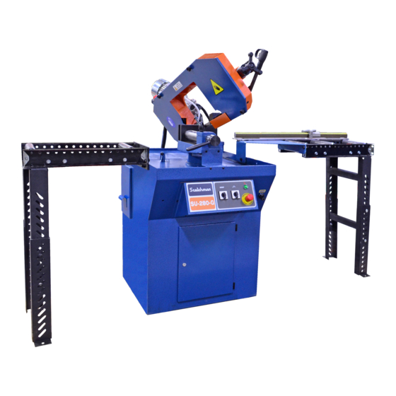
- Page 1 MODEL SU-280/G BAND SAW Page 1...
-
Page 2: Table Of Contents
TABLE OF CONTENTS INTRODUCTION Legislation applicable to planning and construction GENERAL MACHINE INFORMATION Machine Identification Data TECHNICAL DATA Noise level Selection of the Band Saw INFORMATION ABOUT TRANSPORT AND STORAGE INSTRUCTIONS FOR ANCHORING AND SERVICE START-UP Anchoring Instructions Connection to the Electric System Installing the Band Saw Blade Cutting Coolant INSTRUCTIONS FOR USE... -
Page 3: Introduction
1.2 WARRANTY Scotchman Industries, Inc. will, within three years of the date of purchase, replace F.O.B. the factory or refund the purchase price for any goods which are defective in materials or workmanship, provided the buyer, at the seller’s option, returns the defective goods freight and delivery prepaid to the seller, which shall be the buyer’s sole and exclusive remedy for defective... -
Page 4: General Machine Information
2.0 GENERAL MACHINE INFORMATION 2.1 MACHINE IDENTIFICATION DATA Model: _________________ SU-280 Serial number: ___________ Manufacture year: ________ NOTE: In order to request replacement parts, whether they are covered by the warranty or not, always state the model and serial number of the machine, as well as the name of the part and the code that appear in the last chapter of exploded views. -
Page 5: Selection Of The Band Saw
3.2 SELECTION OF THE BAND SAW Page 5... -
Page 6: Information About Transport And Storage
4.0 INFORMATION ABOUT TRANSPORT & STORAGE Due to the size of the machine, it should be transported on a forklift or by a crane bridge, using slings. If the machine is left in storage for a long period of time, lubricate periodically. Do not expose to the elements. -
Page 7: Connection To The Electric System
5.2 CONNECTION TO THE ELECTRIC SYSTEM Ensure that the power supply voltage corresponds to the voltage on the data plate of the machine. Connect the cable (4 x 1.5 sleeve) to the electric system, using a plug that is appropriate for the characteristics of the same, thereby respecting color codes. -
Page 8: Cutting Coolant
5.4 CUTTING COOLANT When filling the cutting coolant, use pure, synthetic water-soluble coolant and pour it in through the coolant down-tube on the machine mount. CAUTION: When it is necessary to empty the liquid coolant tank, do not improperly dispose of the coolant. -
Page 9: Raising And Lowering The Stop
6.3. RAISING AND LOWERING THE STOP The machine is fitted with lowering stops and a mechanical safety stop. Use the washer on the arc bolt to adjust the height. WARNING: When performing the cut, it is important that the saw should be lowered at a constant rate, with no sharp changes of speed. - Page 10 7.0 TROUBLESHOOTING/CORRECTIVE MAINTENANCE PROBLEM POSSIBLE CAUSES The machine does not start. Check that the main switch is connected to the power supply. Motor fuse has blown. 2A fuse has blown. The rear arc guard has not activated the safety micro-switch, or this is not working properly.
-
Page 11: Adjustment Of The Cutting Blade Guides
7.1 ADJUSTMENT OF CUTTING BLADE GUIDES In order to obtain a correctly squared cut, you must make sure that there is a distance of .035 thousandths of an inch (0.9 mm) between the side plates (3), so that they are all in contact with the blade. To adjust this distance, follow the instructions given below: 1. -
Page 12: Recommendations And Maintenance
8.0 RECOMMENDATIONS & MAINTENANCE 8.1 TYPE & FREQUENCY OF REVIEWS LUBRICATION POINTS TYPE OF GREASE/OIL FREQUENCY Arc turning bolt Fig. 11.2 Bearing grease Yearly Long belt-guide bracket Fig. 11.4 SAE 30 Weekly Bearings Fig. 11.4 Bearing grease Weekly CHECK MATERIALS TO USE FREQUENCY Saw blade tension 90-100 BAR (see gauge) -
Page 13: Manufacturer Recommendations
9.1 MANUFACTURER'S RECOMMENDATIONS Repairs shall be made exclusively by qualified personnel; using original replacement parts. If not, the machine may be damaged and the user may be injured. Maintenance and cleaning of the machine must be performed regularly. The life of the machine and its optimal operation depend on it. -
Page 14: Recommended Accessories
10.0 ACCESSORIES Scotchman has several accessories to help with your sawing needs; the first of which are our Material Supply Tracks. They are available in 5' and 10' lengths and can be assembled to as long as needed. The same is true for our Discharge Tracks. They are available with either our Quick-Loc or Multi-Loc measuring systems, which will save you time and increase your productivity. - Page 15 Quick. easy installation Simple keypad design ~ makes every operator your best Works the way you do: Enter feet, inches, fractions & decimal fractions, or switch to metric mode Adjustable stop Flip stop ~ can be flipped up, away from table to back feed Portable power head ~ quickly detaches from rail List storage: Holds 10 lists with up to 10 moves each Quick and easy calibration...
-
Page 16: Drawings And Schematics
10.1 MATERIAL SUPPLY TRACKS A 10’ and 20’ roller supply track is an available option for this saw. They can be bolted to the input side of the saw (either the left or right hand side) to support longer pieces of material. If a longer supply track is needed, these can be bolted together, end to end. - Page 17 Page 17...
- Page 18 10.2 DISCHARGE TRACKS WITH SCALES Roller discharge tracks, equipped with either a Right or Left-Hand Quick-Loc, are available in 5’ and 10’ lengths. If the Left-Hand Quick-Loc is used, we have 10’ and 20’ Right Hand Conveyors available. The discharge track shown mounts to the machine in place of the 30" stop that comes with the machine. The discharge tracks allow fast set-up and accuracy for various lengths of cuts.
- Page 19 Page 19...
- Page 20 11.0 DRAWINGS & SCHEMATICS 11.1 ELECTRICAL SCHEMATIC Page 20...
- Page 21 Page 21...
- Page 22 11.2 MACHINE EXPLODED VIEW Page 22...
- Page 23 Page 23...
- Page 24 11.3 CLAMP (EXPLODED VIEW) Page 24...
- Page 25 11.4 GUIDES (EXPLODED VIEW) Page 25...
Need help?
Do you have a question about the SU-280/G and is the answer not in the manual?
Questions and answers