
Subscribe to Our Youtube Channel
Related Manuals for Scotchman CPO-315-RFA-NF


Summary of Contents for Scotchman CPO-315-RFA-NF
- Page 1 You have downloaded a manual for our MODEL CPO-315-RFA-NF COLD SAW Please read the manual before operating this saw!!
- Page 2 MODEL CPO-315-RFA-NF COLD SAW S/N B2053RFA0522 and up PRINTED SEPTEMBER 2022 SCOTCHMAN INDS. - 180 E US HWY 14 - PO BOX 850 - PHILIP, SD 57567 Call: 1-605-859-2542...
-
Page 3: Table Of Contents
5.1R Load Fault Screen 5.1S Cut Fail Screen Alarms History Menu 5.1T Auto Operation Menu 5.1U MACHINE OPERATION Blade Installation Page 2 SCOTCHMAN INDS. - 180 E US HWY 14 - PO BOX 850 - PHILIP, SD 57567 Call: 1-800-843-8844... - Page 4 Breakage or Excessive Dulling of Blades 10.2 Coolant System 10.3 Pneumatic System 10.4 11.0 PARTS LISTS Drive Assembly 11.1 Main Vise Assembly 11.2 Page 3 SCOTCHMAN INDS. - 180 E US HWY 14 - PO BOX 850 - PHILIP, SD 57567 Call: 1-800-843-8844...
- Page 5 Vise Regulator 12.4 Power Down Feed Regulator 12.4A 90" & 120" Discharge Table Assemblies 12.5 13.0 WIRING DIAGRAM 240V & 480V Page 4 SCOTCHMAN INDS. - 180 E US HWY 14 - PO BOX 850 - PHILIP, SD 57567 Call: 1-800-843-8844...
-
Page 6: Introduction
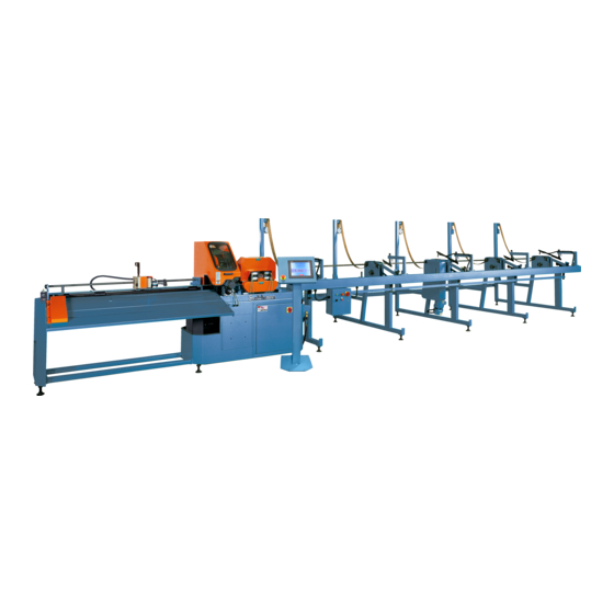
1.0 INTRODUCTION The CPO-315 RFA-NF Fully Automatic Cold Saw is a high speed saw designed to cut solids, tubes, flats and other profiles in grades of nonferrous material that range from aluminum, brass, copper, synthetics and extrusions. Cold sawing is a process similar to a milling process. In most cases, this gives a finished cut that does not require any secondary machining or de-burring. -
Page 7: Safety Precautions
2.0 SAFETY PRECAUTIONS The operators of this machine must be qualified and well trained in the operation of this machine. The operators must be aware of the capacities and the proper use of this machine. This manual is not intended to teach untrained personnel how to operate equipment. NEVER OPERATE THIS MACHINE WITH ANY OF THE PROTECTIVE GUARDS OR HOODS OPEN OR REMOVED! Wear the appropriate personal protective equipment. -
Page 8: Warranty
3.0 WARRANTY Scotchman Industries, Inc. will, within 24 months of date of purchase, replace F.O.B. the factory or refund the purchase price for any goods which are defective in materials or workmanship, provided that the buyer returns the warranty registration card within thirty (30) days of purchase date and, at the seller’s option, returns the defective goods, freight and delivery prepaid, to the seller, which shall be the... -
Page 9: Installation And Set-Up
4.0 INSTALLATION AND SET-UP ⌦ CAUTION: THIS SECTION DISCUSSES INSTALLATION AND SET-UP PROCEDURES. PLEASE READ ALL SECTIONS OF THIS MANUAL THOROUGHLY BEFORE OPERATING THIS MACHINE. 4.1 PHYSICAL DIMENSIONS SEE FIGURE 1 ON THE FOLLOWING PAGE. DIMENSIONS INCHES HEIGHT FLOOR TO VISE 38.5 BASE HEIGHT VISE OPENING... - Page 10 FIGURE 1 Page 9...
-
Page 11: Machine Installation
4.2 MACHINE INSTALLATION SEE FIGURE 2 ON THE FOLLOWING PAGE. This machine is shipped on a pallet with the 60 inch discharge assembly attached to the saw. If the optional 90 or 120 inch discharge assemblies are ordered, they are packaged separately and must be assembled when they arrive. - Page 12 FIGURE 2 Page 11...
-
Page 13: Electrical Requirements
For supply lines ten feet (304 cm) or shorter, we recommend 12 gauge wire. For lines longer than ten feet (304 cm), we recommend 10 gauge wire. We do not recommend supply lines over twenty feet (609 cm) in length. CPO-315-RFA-NF (3,000 RPM) MOTOR VOLTAGE FULL LOAD CURRENT... -
Page 14: Mist Coolant System
4.4 MIST COOLANT SYSTEM The coolant system on this machine is a pneumatic mist type. We recommend using only our P/N 075760, SYNCON-2 coolant in this saw. One gallon of coolant is shipped with the saw. For the best results, we recommend that it is used straight and not diluted. The NF coolant reservoir has a capacity of (5) quarts (4.7 liters). -
Page 15: Machine Start-Up
5.0 MACHINE START-UP Before starting this machine, take the time to review the operator’s manual thoroughly, to familiarize yourself with all of the functions of the machine. We strongly urge you to follow OSHA directive CFR-1910.147 (effective 09-09-90) regarding lock-out, tag-out procedures. -
Page 16: Control Panel Functions
5.1 CONTROL PANEL FUNCTIONS The following section gives a brief description of the touch screen and its functions. Before powering the machine, please familiarize yourself with the location and the function of each of these items. SECTION 7.0 will describe how to set the machine up for an operation. SEE FIGURE 4 BELOW. -
Page 17: A Main Power Switch
5.1 A MAIN POWER SWITCH This is the main power disconnect switch for the machine and it should be locked or tagged in the OFF position any time maintenance or service work is being performed. Maintenance or service work on the electrical controls must be performed by qualified personnel. -
Page 18: B Emergency Stop Switch
5.1 B EMERGENCY STOP SWITCH This switch stops the saw motor and allows the head to return to the up position. The emergency stop switch also applies the material vise air pressure. Once this switch has been used, the operator must restart the machine. -
Page 19: F Cut Profiles
5.1F CUT PROFILES This is the CUT PROFILES MENU. Before performing any operation, you need to set up a cut profile operation. The only profiles that come with the machine are the general or metric profile. You can store up to 100 profiles. Press the recipe screen and name the profile. You can use any combination of numbers or letters that you want for each particular profile. -
Page 20: G Manual Operation Menu
5.1G MANUAL OPERATION MENU This is the MANUAL OPERATION MENU. The manual operation mode is used to calibrate the stop, make sample cuts and set the stroke and other settings of the machine. All of the functions in the manual menu will function when the saw hood is open, except the START blade function, the head up and the head down buttons. -
Page 21: H Customer Calibration & Set-Up
5.1H CUSTOMER CALIBRATION & SET-UP This is the CALIBRATION SCREEN. This screen is used to calibrate the length stop on the saw. Just follow the instructions on the screen to calibrate the stop. Set your stop 3 to 4 inches from the saw blade. The part count direction will either count parts up to your pre-set number on the counter or down from the pre-set number. -
Page 22: I Desired Length Screen
5.1I DESIRED LENGTH SCREEN This is the DESIRED LENGTH SCREEN. Any time you move the stop, this screen will open. Move the stop until the desired length appears on the screen. The stop has a fine adjustment knob on it that you can fine tune the length with when you are close to your desired length. -
Page 23: J Factory Set-Up Screen
5.1J FACTORY SET-UP SCREEN This is the FACTORY SET-UP SCREEN. These settings are pre-set at the factory and should not need to be changed. The vise release setting chooses whether the vise opens when the blade is down or up. Having the vise release in the down position will speed up the cutting operation. -
Page 24: K Model & Serial Number Menu
5.1K MODEL & SERIAL NUMBER MENU This is the MODEL AND SERIAL NUMBER MENU. You will need the information on the screen when contacting the manufacturer for replacement parts or troubleshooting assistance. FIGURE 11 Page 23... -
Page 25: L Maintenance Menu
5.1L MAINTENANCE MENU This is the MAINTENANCE MENU. The PLC menu is used for most troubleshooting problems. The VFD menu is used for the same. Each menu will be covered on the following pages. FIGURE 12 Page 24... -
Page 26: M Timer Screen
5.1M TIMER SCREEN This is the TIMER SCREEN. This screen is used to set the times for all functions of the saw. FIGURE 13 Page 25... -
Page 27: N Plc Maintenance Screen
5.1N PLC MAINTENANCE SCREEN This is the PLC MAINTENANCE SCREEN. This screen can be used to diagnose most problems with the machine if a fault code does not appear on the screen. For example, if the machine won’t start an operation and you come to this screen and the saw head up light is not lit, this means that the saw head is either not all the way up or the proximity switch is bad or not properly aligned. -
Page 28: O Hood Open Screen
5.1O HOOD OPEN SCREEN This is the HEAD OPEN SCREEN. This just means that the cycle has been stopped because the hood is open. If HOOD OPEN this screen appears and the hood is not open, there is a CYCLE STOPPED!! problem with the hood safety switch. -
Page 29: Q Feed Failure Screen
5.1Q FEED FAILURE SCREEN This is the FEED FAILURE SCREEN. If this screen pops up, you could have one of several problems. The infeed rate on your profile is set too slow and the cycle times out before the material reaches the stop. -
Page 30: S Cut Fail Screen
5.1S CUT FAIL SCREEN This is the CUT FAIL SCREEN. This means that the cut cycle timed out before the head reached the down position. You will need to increase the down feed rate or edit the material feed watchdog in the timer menu. FIGURE 19 5.1T ALARMS HISTORY MENU This is the ALARMS HISTORY MENU. -
Page 31: U Auto Operation Menu
5.1U AUTO OPERATION MENU This is the AUTO OPERATION MENU. In order for the machine to operate in the auto mode, there must be a profile loaded. Make sure that you have the correct profile for the job you are running. There must be a value on the parts counter. -
Page 32: Machine Operation
6.0 MACHINE OPERATION 6.1 BLADE INSTALLATION SEE FIGURE 22 BELOW. ⌦ CAUTION: THIS MACHINE IS DESIGNED TO USE CARBIDE TIPPED BLADES, ONLY. USE ONLY BLADES DESIGNED FOR THIS MACHINE. DO NOT MODIFY ANY BLADE TO FIT THIS MACHINE. DO NOT USE BLADES DESIGNED FOR THIS MACHINE ON ANY OTHER EQUIPMENT. - Page 33 The CPO-315-RFA-NF saw is designed to use a maximum 12 inch (300mm) diameter blade. The arbor size is 40mm with four 12mm pins spaced at 64mm. We offer 72 tooth and a 120 tooth saw blades for this saw. The 120 works well with thin wall tube or material with a thin cross section. The 72 tooth blade works well with solids and heavy walled tube.
-
Page 34: Saw Capacities
6.2 SAW CAPACITIES SEE FIGURE 23 BELOW. Figure 23 is a chart showing the maximum capacities of this machine in various materials. RFA/ST RFA/ST CAPACITIES WITH MAXIMUM DIAMETER 90° ONLY 90° ONLY BUNDLE FEED BLADES 315 MM INCHES Ø3-1/2 Ø3 Ø3 Ø89 Ø76... -
Page 35: Material Main Vise
6.3 MATERIAL MAIN VISE SEE FIGURE 24 BELOW. The following are set-up and maintenance instructions for the material main vise. 1. Make sure that the filter/lubricating device (A) is full of oil. Use a quality (ISO 22) air line lubricant designed for automatic oilers. 2. - Page 36 5. Adjust the air pressure regulator (C). 90 PSI (6.2 BAR) is the minimum operating pressure. 105 PSI (7.2 BAR) is the maximum. 6. The vise is activated by the top proximity switch on the saw head. 7. The lubricating device (A) should release one drop of oil every 5 to 10 cycles. On top of the lubricating device is a clear plastic dome with a small tube inside.
-
Page 37: Power Down Feed
6.4 POWER DOWN FEED REFER TO FIGURE 26 BELOW. FIGURE 26 Page 36... -
Page 38: Material Clamping
CAUTION: ALWAYS DISCONNECT THE AIR SUPPLY BEFORE REMOVING THE FILLER PLUG FROM THE RESERVOIR. IF THE FILLER PLUG IS REMOVED WHILE THE MACHINE IS CONNECTED TO AIR PRESSURE, THE FLUID IN THE TANK WILL BE PURGED THROUGH THE OPENING UNDER PRESSURE. 1. -
Page 39: Stroke Control Adjustment
6.6 STROKE CONTROL ADJUSTMENT ► NOTE: WHEN SWITCHING TO A LARGER BLADE OR BIGGER MATERIAL, THE UPPER STOP (C) MAY NEED TO BE RAISED TO GAIN CLEARANCE. SEE FIGURE 27 ON THE FOLLOWING PAGE. Make sure the shuttle valve (G) is open (air is on) and place a piece of material that you are going to cut in the vise. - Page 40 NOTE: HOOD AND BLADE GUARD ARE NOT SHOWN FOR CLARITY FIGURE 27 Page 39...
-
Page 41: Stop Digital Readout Set-Up
6.7 STOP DIGITAL READOUT SET-UP SET COUNTER: It is possible to alter the indicated value by using the front located keys: Re-set Counter: Press F + RE-SET at the same time. Pre-Set Datum: Press F + SET at the same time. The indicator begins to count up (adding) at three progressive speed rates: Rate 1: 1 Hz for 10 sec. -
Page 42: Machine Automatic Operation (Set-Up)
7.0 MACHINE AUTOMATIC OPERATION (SET-UP) Load the material on the supply table. Load one layer only; do not stack material on the supply table. Stacking material will cause the machine to load more than one part and the machine will fault out. - Page 43 Press the feed advance button and feed the material to the stop. You may have to press the rocker forward button if the rocker feed rollers are not in the correct position. Press the vise close button. Press the coolant start button and blade start button. Press the head down button and make a cut.
-
Page 44: Maintenance
8.0 MAINTENANCE 8.1 LUBRICATION SEE FIGURE 30 BELOW. Grease the head pivot pin (C), the spindle shaft and the feed roller bearings (A) with a high pressure, high temperature bearing grease, daily. Clean the chips out of the vise at least once a day; more often, if needed. Apply penetrating oil to the spindle and guide pins. -
Page 45: Cutting Oils And Lubricants
8.2 CUTTING OILS AND LUBRICANTS SECTION 12.1 lists Scotchman’s parts numbers for cutting oils and lubricants. Using high quality lubricants and oils will greatly increase the life of this equipment. We recommend our P/N 075760 coolant (SYNCON-2) straight and not diluted. -
Page 46: Scheduled Maintenance
8.3 SCHEDULED MAINTENANCE A program of scheduled maintenance should be set up and documented according to your application and the frequency you use this machine. The following is a list of some important things that should be included in a scheduled maintenance program. 1. -
Page 47: Spindle Bearing Replacement
8.4 SPINDLE BEARING REPLACEMENT REFER TO FIGURE 31 BELOW. FIGURE 31 Page 46... - Page 48 Replacing the spindle or spindle bearings on this machine is not an easy task. You may want to consider ordering the spindle shaft assembly which includes parts F, G, H, I, J, K, L and P. TO REMOVE THE SPINDLE, USE THE FOLLOWING STEPS: Remove the lock nut (C) and pull the belt sprocket (D) off the end of the shaft.
-
Page 49: Spindle Replacement (Main Vise)
8.5 SPINDLE REPLACEMENT (MAIN VISE) SEE FIGURE 32 BELOW. FIGURE 32 Page 48... -
Page 50: Seal Replacement (Main Vise)
Disconnect the machine’s power and the air supply. Remove the spindle shield (XX) and the spring (Y) and ball (HH). Remove the bolts (A & B) and the retainer (D). Remove the clevis pin (F) and remove the clevis (E) and the forks (CC). The spindle can now be removed from the machine. -
Page 51: Optional Equipment
9.0 OPTIONAL EQUIPMENT 9.1 SPECIAL VISE JAWS Special vise jaws for holding thin wall round tubes, profiles and bundles are available on a made-to-order basis. For prices and delivery on special jaws, contact your local dealer or the factory. For examples, REFER TO FIGURE 25 ON PAGE 35. -
Page 52: Trouble Shooting Guide
10.0 TROUBLE SHOOTING GUIDE 10.1 ELECTRICAL TROUBLE SHOOTING 1. THE MOTOR WILL NOT RUN. The main disconnect switch in the base cabinet must be on and the emergency stop switch must be pulled out. The saw hood must be closed for the motor to run. The MOTOR CONTROL switch must be in the ON position to start the saw motor. -
Page 53: Breakage Or Excessive Dulling Of Blades
10.2 BREAKAGE OR EXCESSIVE DULLING OF BLADES Select the proper blade. FOR RECOMMENDATIONS, REFER TO SECTION 6.1. Always break in the blade before you start normal cutting. Do not apply excessive down pressure on the workpiece. Excessive down pressure will cause the teeth to remove too large of a chip, resulting in premature dulling or breakage. -
Page 54: Coolant System
10.3 COOLANT SYSTEM 1. IF COOLANT WILL NOT FLOW: A. Check the suction line between the reservoir and the mister unit. If there are any cracks or poor connections on the line, it will not siphon the coolant out of the reservoir. B. -
Page 55: Pneumatic System
10.4 PNEUMATIC SYSTEM REFER TO FIGURE 34 ON THE FOLLOWING PAGE. THE MOST COMMON PNEUMATIC/HYDRAULIC PROBLEMS ARE: Low levels of fluid in the reservoir: The fluid level in the power down feed reservoir should be approximately 2-1/2 inches below the top of the reservoir when the head is in the up position. CAUTION: THE AIR SUPPLY TO THE MACHINE MUST BE DISCONNECTED BEFORE YOU REMOVE THE FILLER PLUG FROM THE RESERVOIR. - Page 56 1A-5/16" BLACK TO BACK OF VISE CYLINDER 1B-5/16" BLACK TO FRONT OF VISE CYLINDER 2A-1/4" RED TO TOP OF POWER-DOWN OIL TANK 2B-1/4" GREEN THRU TEE TO THE REGULATOR ON BACK OF CYLINDER, SIDE OF TEE THRU 12# REG., 5/16" BLACK TO MISTER 3A-1/4"...
- Page 57 BEST IN THE BUSINESS WARRANTY WWW.SCOTCHMAN.COM Page 56...
- Page 58 SCOTCHMAN CPO-315-RFA-NF SAW WWW.SCOTCHMAN.COM SCOTCHMAN INDS. - 180 E US HWY 14 - PO BOX 850 - PHILIP, SD 57567 Call: 1-605-859-2542 Page 57...
-
Page 59: Parts Lists
11.0 PARTS LIST THE FOLLOWING SECTIONS CONTAIN THE SAW AND OPTIONAL EQUIPMENT PARTS LISTS AND DRAWINGS. FOR YOUR CONVENIENCE, ALWAYS GIVE YOUR COMPLETE SERIAL NUMBER WHEN ORDERING PARTS! 11.1 DRIVE ASSEMBLY ITEM PART # DESCRIPTION 677912 Belt Guard 077915 Belt 077189 Lock Nut 077898... - Page 60 073328 M-8 x 40 HHCS 073326 M-8 x 25 HHCS 073920 M-10 Dowel Pin 077929 Spindle Assembly (Includes F, G, H, I, J, K & L) FIGURE 35 Page 59...
-
Page 61: Main Vise Assembly
11.2 MAIN VISE ASSEMBLY ITEM PART # DESCRIPTION 221245 10 x 160 MM SHCS 221240 10 x 140 MM SHCS 221235 10 x 100 MM SHCS 045311 Clevis Guide 045312 Clevis 045317 Clevis Pin 046655 Snap Ring 045630 Cylinder 045631 Cylinder Seal Kit 045313 Cylinder Mount... - Page 62 219047 M-10 x 10 Set Screw 077798 Vise Jaws 203212 M-10 x 30 HHCS 045224 Strike Plate 060270 Covering Cap 114020 Washer 210012 M-10 Jam Nut 045300 Complete Vise Assembly FIGURE 36 Page 61...
-
Page 63: A Infeed Roller Assembly
11.3A INFEED ROLLER ASSEMBLY ITEM PART # DESCRIPTION Drive Roller (Urethane) 042036 220020 Button Head 046130 Retainer Upper Roller Bearing 046003 042018 Drive Roller Sleeve 043156 Roller Shaft 045178 Pivot Plate 077189 M-20 Hex Nut Idler Sprocket 043082 221317 M-12 SHCS 218022 M-6 Set Screw Drive Sprocket Assembly... - Page 64 Snap Ring 077191 Drive Sprocket Bearing 046006 FIGURE 37 Page 63...
-
Page 65: B Infeed Drive Assembly
11.3B INFEED DRIVE ASSEMBLY ITEM PART # DESCRIPTION 045279 Support Leg 043003 Guide Roller 046024 Bearing and Retainer 079213 Roller 045234 Front Side Plate 045236 End Plate 043082 Idler Sprocket 045244 Feed Roller 042024 Drive Roller 045243 Guide Plate 045235 Rear Side Plate 045237 Sensor Mount... - Page 66 FIGURE 38 Page 65...
-
Page 67: C Roller Drive Assembly
11.3C ROLLER DRIVE ASSEMBLY ITEM PART # DESCRIPTION 045242 Valve Bracket 045614 Rotary Actuator 121205 3/8 x 1 SHCS 043082 Sprocket 101412 1/2 x 13 x 1-1/2 HHCS 221230 M-10 x 60 SHCS 045139 Sprocket Mount 046115 #35 Chain (46 Link) 046033 Connecting Link 042051... - Page 68 FIGURE 39 Page 67...
-
Page 69: D Infeed Guide Assembly
11.3 D INFEED GUIDE ASSEMBLY ITEM PART # DESCRIPTION 045245 Platform Assembly 079213 Vertical Guide Roller 229220 M-12 x 20 x 50 Shoulder Bolt 045279 Roller Mount 043003 Nylon Roller 229225 M-10 x 12 x 70 221210 M-10 x 25 SHCS 114020 Hardened Washer 043018... - Page 70 FIGURE 40 Page 69...
-
Page 71: Encoder Assembly
11.4 ENCODER ASSEMBLY ITEM PART # DESCRIPTION 045572 Spring 210012 M-10 Jam Nut 045293 Mounting Plate 045292 Spacer 046563 Rubber Wheel 044410 Abrasive Band 046046 Snap Ring 045564 Bearing 045291 Hub Bolt 045290 Wheel Insert 045566 Wheel Pulley 045570 Belt 073605 6 x 32 x 5/8 SHCS 045321... - Page 72 FIGURE 41 Page 71...
-
Page 73: 60" Discharge Table Assembly
11.5 60" DISCHARGE TABLE ASSEMBLY ITEM PART # DESCRIPTION 045138 Leg Assembly 049330 Foot Clamp 049217 Leveling Pads 045146 Support Assembly 221210 M-10 x 25 SHCS 045611 Rotary Actuator 077746 Fitting 045454 Left End Plate 221220 M-10 x 40 SHCS 045167 Wire Channel 073420... - Page 74 045164 Table Slide Rail 114020 Washer 221212 M-10 x 30 SHCS 077746 1/4 x 90 Swivel Fitting 045581 Cylinder Clevis 045582 Clevis Pin FIGURE 42 Page 73...
-
Page 75: Stop Assembly
11.6 STOP ASSEMBLY ITEM PART # DESCRIPTION 044222 Aluminum Rail 045453 End Plate 073624 M-8 x 25 FSHCS 044238 T-Nut 130105 5/16 x 18 x 3/4 FSHCS 044212 T-Rail 044139 Stop Shaft 044218 Collett Holder 044228 Collett 220014 M-6 x 10 BHCS 044137 Shaft Support 044282... - Page 76 FIGURE 43 Page 75...
-
Page 77: Stop Adjustment Assembly
11.7 STOP ADJUSTMENT ASSEMBLY ITEM PART # DESCRIPTION 045472 Stop Nut 043108 Fine Adjustment 045287 Stop Adjustment Rod 141619 1/8 x 7/8 Roll Pin 073458 M-6 x 10 SHCS 046029 Spring 042034 Material Stop 141215 3/16 x 1-1/2 Roll Pin 047601 Stop Cylinder 045286... - Page 78 FIGURE 44 Page 77...
-
Page 79: Supply Table Assembly
11.8 SUPPLY TABLE ASSEMBLY ITEM PART # DESCRIPTION 045101 Guide Assembly 045126 Material Guide 045131 Adj. Guide Arm 045123 Guide Mount 045129 Roller Block 043003 Guide Roller 045145 20' Carrier Beam 045405 Stand Assembly Top 045383 Cyl. Mtg. Block 045385 Bearing Mount 049321 Fafnir Bearing SCJT 1... - Page 80 DETAIL B DETAIL C Page 79 DETAIL A FIGURE 45...
-
Page 81: A Supply Table Leg Assemblies
11.8A SUPPLY TABLE LEG ASSEMBLIES ITEM QTY PART # DESCRIPTION 079210 Horizontal Roller 079221 Nice Bearing 079211 Roller Shaft 214016 M-16 Washer 079212 Roller Stand 079213 Vertical Roller 229220 M-10 x 12 x 50 SH Bolt 219047 M-10 x 12 SS 045105 Stand Ass'y 114020... - Page 82 FIGURE 46 Page 81...
-
Page 83: Power Down Feed Assembly
11.9 POWER DOWN FEED ASSEMBLY PART # DESCRIPTION ITEM Power Down Feed Cylinder 077706 045425 Reservoir Pivot Bolt - Package of (2) 077715 Cylinder Bracket 045232 TPC Cyl. Nut-Machined 077512 Right Angle Flow Control 041015 M-10 x 30 SHCS 221212 Upper Bracket Assembly 047100 221210... - Page 84 FIGURE 47 Page 83...
-
Page 85: A Power Down Feed Valves
11.9A POWER DOWN FEED VALVES ITEM PART # DESCRIPTION 077746 1/4" NPT x 169PL 077701 Baffle 077777 3/8" NPT Plug 045054 1/2 x Ninety Degree Swivel x 169PL 077536 Check Valve 045042 1/2" Straight Fitting 047535 Flow Control Valve 045054 1/2 x Ninety Degree Swivel x 169PL 077779 1/4 NPT Close Nipple... - Page 86 FIGURE 48 Page 85...
-
Page 87: B Air Controls
11.11 POWER DOWN FEED ASSEMBLY ITEM PART # DESCRIPTION 045230 Power Down Bracket (Upper) 045425 Power Down Reservoir CPO315 PD Cylinder Assembly 045692 (Includes Items 3-14) 045031 3/8" NPT X 1/4" 90° Swivel 045054 3/8" NPT X 1/2" 90° Swivel Pivot Pin 045593 (Includes Items 6-7) - Page 88 FIGURE 49 Page 87...
-
Page 89: Air Valve Assembly
11.10 AIR VALVE ASSEMBLY ITEM PART # DESCRIPTION 045560 Cable End 677728 Fitting (1/4 NPT to 1/4 ITOS) 077777 Plug (3/8 NPT) 045045 Vent (3/8) 077738 90 Degree Elbow 077771 Bushing 045650 Solenoid 045655 Valve 077744 Fitting 077930 Coolant Regulator 045603 Complete Valve Assembly Page 88... - Page 90 FIGURE 50 Page 89...
-
Page 91: Blade Guard Assembly
11.11 BLADE GUARD ASSEMBLY ITEM PART # DESCRIPTION 045267 Guard Shell 677901 M-10 SHCS 076839 Mister Unit 676842 Fitting 077926 Coolant Line 060501 Air Line 676844 Hose Barb 073095 M-4 Washer 073415 M-4 SHCS Page 90... - Page 92 FIGURE 51 Page 91...
-
Page 93: Motor Assembly
11.12 MOTOR ASSEMBLY ITEM PART # DESCRIPTION 076883 Fan Cover 073407 M-5 x 8 SHCS 076881 Fan (25mm Bore) 076884 Fan (30mm Bore) 077380 End Casting (25mm Bore) 077381 End Casting (30mm Bore) 075049 Motor Bearing (6205Z) (25mm) 077325 Motor Bearing (6206) (30mm) 077191 Snap Ring 076369... - Page 94 FIGURE 52 Page 93...
-
Page 95: Electrical Unit - Line Circuit
11.13 ELECTRICAL UNIT - LINE CIRCUIT ITEM # PART # DESCRIPTION 230V 1/2 HP VFD Programmed 460v 1/2 HP VFD Programmed 045495 15A Breaker 230V 045530 8A Breaker 460V 045496 30A Breaker 230V 045529 15A Breaker 460V 078285 5HP 230V VFD-Programmed 078286 5HP 460V VFD-Programmed 045497... - Page 96 ITEM # PART # DESCRIPTION 045508 9A DC Contactor 045509 Starter Auxilary 045510 Manual Starter 045511 2P Relay Base 045512 24 VDC Relay 045514 Tan Terminal 045515 White Terminal 045516 Ground Terminal 045517 Terminal Barrier 045518 Terminal Anchor 045519 2P Fuse Holder 045521 1P Mini Fuse Holder 045522...
- Page 97 F, J, & HH I, K, L FIGURE 55 FIGURE 53 Page 96...
- Page 98 THIS PAGE LEFT BLANK INTENTIONALLY. Page 97...
-
Page 99: Base Assembly
11.14 BASE ASSEMBLY ITEM PART # DESCRIPTION 203235 M-10 x 90 HHCS 045411 Base Casting 216015 M-10 Flange Nut 045171 Base Cabinet 045735 Lower Enclosure 046642 Door Assembly 049217 Leveling Pads 208024 M-24 Nut 049330 Foot Clamp 073617 M-6 x 12 BHCS 046018 Handle 045052... - Page 100 FIGURE 54 Page 99...
-
Page 101: Mist Coolant System
11.15 MIST COOLANT SYSTEM ITEM PART # DESCRIPTION 677728 1/4 NPT x 1/4 Hose 677745 1/4 Brass Tee 077748 1/4 To 1/8 NPT Reducer 077750 1/8 x 2-1/2 Pipe Nipple 077930 Mister Regulator 677933 Mister Reservoir 077779 1/4" Brass Nipple 077741 5/16 Elbow 045740... - Page 102 FIGURE 55 Page 101...
-
Page 103: Stroke Control Assembly
11.16 STROKE CONTROL ASSEMBLY ITEM PART # DESCRIPTION 045253 Stroke Adjustment Plate 045249 Stroke Control Stand 045299 Stop Block 045320 Stroke Sensor Mount 045330 Stop Guide 220010 M-4 x 12 BHCS 203212 M-10 x 30 HHCS 114020 M-10 Flat Washer 077796 Proximity Switch 221212... - Page 104 FIGURE 56 Page 103...
-
Page 105: Hood Assembly
11.17 HOOD ASSEMBLY ITEM PART # DESCRIPTION 203217 M-10 x 45 HHCS 045196 Pedestal 047180 Chip Chute 046018 Hood Handle 045322 Sight Glass 046645 Sight Glass Seal 229415 M-10 x 12 x 16 Shoulder Bolt 047151 Hood (Painted) 077142 Grease Nipple 077100 M-10 Dowel Pin 073617... - Page 106 FIGURE 57 Page 105...
-
Page 107: Optional Equipment Parts Lists
12.0 OPTIONAL EQUIPMENT PARTS LISTS 12.1 CUTTING COOLANTS AND LUBRICANTS UNIT PART DESCRIPTION 1 Gal. 075760 1 GAL. SYNCON-2 (do not dilute) 55 Gal. 075761 55 GAL. SYNCON-2 (do not dilute) 1 Qt. 075753 Air Line Lubricant 1 Gal. 075759 Air Line Lubricant Page 106... -
Page 108: Digital Readout
12.2 DIGITAL READOUT ITEM PART # DESCRIPTION 047090 Axis Display 220105 M-3 x 16 SHCS 044091 Vertical Bracket 073400 M-5 x 30 SHCS 044092 Scale Assembly 220100 M-3 x 10 SHCS 208010 M-8 Hex Nut 026504 M-8 x 16 Brass S.S. 044090 Horizontal Mount 073605... -
Page 109: Overturn Device
12.3 OVERTURN DEVICE ITEM PART # DESCRIPTION 045344 Slider 229212 M-8 x 10 x 60 Shoulder Bolt 045346 Roller 045348 Roller Bracket 045347 Roller Bracket 073420 M-8 x 16 SHCS 221120 M-8 x 25 SHCS 045352 Overturn Device Page 108... - Page 110 FIGURE 59 Page 109...
-
Page 111: Vise Regulator
12.4 VISE REGULATOR PART # DESCRIPTION ITEM Regulator 078190 Gauge 077538 677934 Wall Mount 077864 M-5 x 12 SHCS 077742 1/4 Male Swivel x 169PL 1/4 x 5/16 NPT Fitting 077744 060501 5/16 Black Hose Complete Regulator Assembly 047250 12.4A POWER DOWN FEED REGULATOR Regulator 078190 677934... - Page 112 FIGURE 60 Page 111...
-
Page 113: 90" & 120" Discharge Table Assemblies
12.5 90 & 120 INCH DISCHARGE TABLE ASSEMBLIES SEE SECTION 11.5 FOR PARTS THAT ARE COMMON TO ALL DISCHARGE TABLES. ITEM PART # DESCRIPTION 044321 044319 Table (Short) 044323 044317 Table (Long) 044161 044161 Table Support (Long) 044235 044235 Bushing 043035 043035 Coupler... - Page 114 FIGURE 61 Page 113...
-
Page 115: Wiring Diagram 240V & 480V
13.0 WIRING DIAGRAMS - S/N B2053RFA0522 and up Scotchman Industries Cold Saw RFA 240V POWER CONNECTIONS TO 240 Vac FIELD WIRING TO BE INSTALLED BY UL FUSE OR CB INSTALLING ELECTRICIAN RATED AT 30A #10AWG GROUND GROUND LUG TA2/0 #10 GRN... - Page 116 Scotchman Industries Cold Saw RFA 480V POWER CONNECTIONS* TO 480 Vac FIELD WIRING TO BE INSTALLED BY UL FUSE OR CB INSTALLING ELECTRICIAN RATED AT 20A #10AWG GROUND GROUND LUG TA2/0 #10 GRN LK4DU3CN PART # PK9GTA BRAKING RESISTOR FOUND IN NF VERSION...
- Page 117 Scotchman Industries Cold Saw RFA FROM PAGE 1 1CR - STOP HMI PANEL STOP FROM PAGE 1 ORANGE YELLOW/BLACK TELEMECANIQUE - HMI YELLOW/RED P/N# HMIGT05330 YELLOW/BLACK 192.168.1.13 RS485 ETHERNET CAT 5 MALE TO MALE CON. ECAT5-4PR03BKB RJ45C5X01PU ETHERNET PORT ECAT5-4PR25BKB ON TWIDO MODBUS "T"...
- Page 118 Scotchman Industries Cold Saw RFA FROM PAGE 2 FROM PAGE 2 GCC1 YELLOW/RED YELLOW/BLACK TM221CE40T SHOWN AGAIN FROM CR1 ON PG 2 24VDC YELLOW/BLACK %I0.0.0 %Q0.0.0 "A" PUL WHL ENC SAW RUN CMD GRY/WHT %Q0.0.1 %I0.0.1 "B" PUL WHL ENC GRY/YEL %Q0.0.2...
- Page 119 Scotchman Industries Cold Saw RFA FROM PAGE 3 FROM PAGE 3 YELLOW/BLACK ROLLER SENSOR #2 YELLOW/RED IN 14 BLACK/WHITE SEE PG 3 SAW HEAD UP IN 9 BLUE/YELLOW SEE PG 3 YELLOW/BLACK MATERIAL HARD STOP YELLOW/RED IN 16 RED/BLUE SEE PG 3...
- Page 120 Scotchman Industries Cold Saw RFA FROM PAGE 4 FROM PAGE 4 YELLOW/RED LOAD PART GCC 3A GRAY/YELLOW BLACK YELLOW/BLACK ROCKER BLUE/YELLOW HEAD DOWN BLUE/RED YELLOW/BLACK VISE RELEASE EJECT RED/WHITE YELLOW/BLACK YELLOW/RED DUMP GCC 3A BLU/BLK BLACK HARD STOP RED/YELLOW YELLOW/BLACK...
- Page 121 Scotchman Industries Cold Saw RFA VFD CONNECTIONS SAW VFD SAW VFD PUR/RED PUR/BLK FEED VFD BLK/WHT RED/BLK FEED VFD BLK/WHT GRY/BLK FEED VFD BLK/WHT BRW/YEL FEED VFD LOW SPEED 1 BLK/WHT GRY/RED FEED VFD LOW SPEED 2 SPECIAL OPTION GRY/WHT...
Need help?
Do you have a question about the CPO-315-RFA-NF and is the answer not in the manual?
Questions and answers