
Subscribe to Our Youtube Channel
Related Manuals for Scotchman CPO-315-HFA-NF


Summary of Contents for Scotchman CPO-315-HFA-NF
- Page 1 You have downloaded a manual for our MODEL CPO-315-HFA-NF COLD SAW Please read the manual before operating this saw!!
- Page 2 MODEL CPO-315-HFA-NF COLD SAW PRINTED MAY 2021 SCOTCHMAN INDS. - 180 E US HWY 14 - PO BOX 850 - PHILIP, SD 57567 Call: 1-605-859-2542...
-
Page 3: Table Of Contents
TABLE OF CONTENTS SECTION DESCRIPTION PAGE # INTRODUCTION SAFETY PRECAUTIONS WARRANTY INSTALLATION & SET-UP Physical Dimensions Machine Installation Electrical Requirements Coolant System MACHINE START-UP Control Panel Functions MACHINE OPERATION Blade Installation Saw Capacities Main Vise Shuttle Vise Power Down Feed Material Clamping Stroke Control Adjustment Counter Set-up... - Page 4 TABLE OF CONTENTS SECTION DESCRIPTION PAGE # OPTIONAL EQUIPMENT Special Vise Jaws Optional In Feed Supply Tracks 10.0 TROUBLE SHOOTING GUIDE 10.1 Electrical Trouble Shooting 10.2 Breakage or Excessive Dulling of Blades 10.3 Part Lengths Not Consistent 10.4 Coolant System 10.5 PLC (LED’s) 10.6...
-
Page 5: Introduction
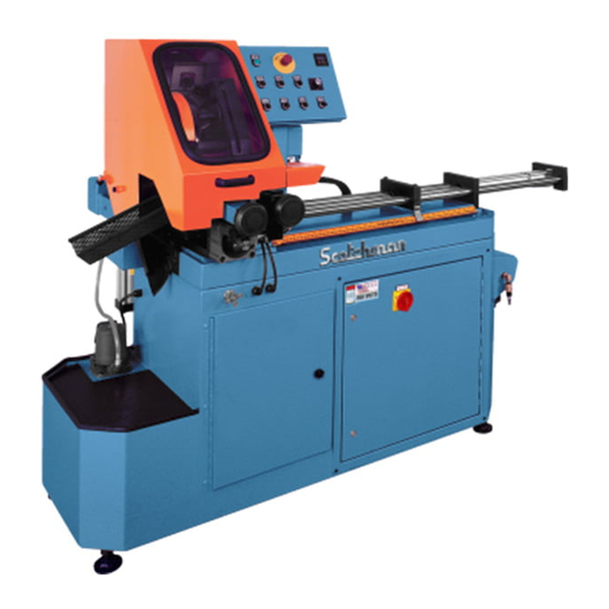
1.0 INTRODUCTION The CPO-315 HFA-NF Fully Automatic Cold Saw is a high speed saw designed to cut solids, tubes, flats and other profiles in grades of nonferrous material that range from aluminum, brass, copper, synthetics and extrusions. Cold sawing is a process similar to a milling process. In most cases, this gives a finished cut that does not require any secondary machining or de-burring. -
Page 6: Warranty
3.0 WARRANTY Scotchman Industries, Inc. will, within 2 years of date of purchase, replace F.O.B. the factory or refund the purchase price for any goods which are defective in materials or workmanship, provided that the buyer returns the warranty registration card within thirty (30) days of purchase date, and at the seller’s option, returns the defective goods, freight and delivery prepaid, to the seller, which shall be the... -
Page 7: Installation & Set-Up
4.0 INSTALLATION AND SET-UP CAUTION: THIS SECTION DISCUSSES INSTALLATION AND SET-UP PROCEDURES. PLEASE READ ALL SECTIONS OF THIS MANUAL THOROUGHLY BEFORE OPERATING THIS MACHINE. 4.1 PHYSICAL DIMENSIONS SEE FIGURE 1 ON THE FOLLOWING PAGE. DIMENSIONS INCHES HEIGHT FLOOR TO VISE 38.5 BASE HEIGHT VISE OPENING... - Page 8 FIGURE 1 Page 7...
-
Page 9: Machine Installation
4.2 MACHINE INSTALLATION SEE FIGURE 2 ON THE FOLLOWING PAGE. This machine is shipped on a pallet and can be moved to the installation location by means of a fork lift. CAUTION: THIS MACHINE IS TOP HEAVY AND MUST BE MOVED WITH CARE, ON HARD FLAT SURFACES ONLY. - Page 10 FIGURE 2 Page 9...
-
Page 11: Electrical Requirements
For supply lines ten feet (304 cm) or shorter, we recommend 12 gauge wire. For lines longer than ten feet (304 cm), we recommend 10 gauge wire. We do not recommend supply lines over twenty feet (609 cm) in length. CPO-315-HFA-NF (3,000 RPM) MOTOR VOLTAGE FULL LOAD CURRENT... -
Page 12: Coolant System
4.4 COOLANT SYSTEM The coolant system on this machine is a pneumatic mist type. We recommend using only our P/N 075760, SYNCON-2 coolant in this saw. One gallon of coolant is shipped with the saw. For the best results, we recommend that it is used straight and not diluted. The NF coolant reservoir has a capacity of (5) quarts (4.7 liters). -
Page 13: Machine Start-Up
5.0 MACHINE START-UP Before starting this machine, take the time to review the operator’s manual thoroughly, to familiarize yourself with all of the functions of the machine. We strongly urge you to follow OSHA directive CFR-1910.147 (effective 09-09-90) regarding lock-out, tag-out procedures. - Page 14 FIGURE 3 Page 13...
- Page 15 5.1A MAIN POWER SWITCH This is the main power disconnect switch for the machine and it should be locked or tagged in the OFF position any time maintenance or service work is being performed. Maintenance or service work on the electrical controls must be performed by qualified personnel.
- Page 16 5.1F HEAD DOWN This button is also used to set the overall stroke of the machine and to make manual cuts. 5.1G HITCH SELECTOR This switch is used to select the number of hitches the shuttle vise makes before the saw makes a cut. POSITION 1 is for parts from 0 to thirty inches in length.
- Page 17 5.1L POWER INDICATOR LIGHT This switch indicates that the main switch (A) is on and that there is power to the control panel. 5.1M COUNTER This counter can be programmed to count up or down, depending on your preference. The counter is programmed from the factory to count up.
- Page 18 THIS PAGE LEFT BLANK INTENTIONALLY. Page 17...
-
Page 19: Machine Operation
6.0 MACHINE OPERATION 6.1 BLADE INSTALLATION SEE FIGURE 4 BELOW. CAUTION: THIS MACHINE IS DESIGNED TO USE CARBIDE TIPPED BLADES, ONLY. USE ONLY BLADES DESIGNED FOR THIS MACHINE. DO NOT USE BLADES DESIGNED FOR THIS MACHINE ON ANY OTHER EQUIPMENT. THE MAXIMUM RPM’S FOR THESE BLADES ARE 4,000. - Page 20 The CPO-315-HFA-NF saw is designed to use a maximum 12 inch (300mm) diameter blade. The arbor size is 40mm with two 8mm pins spaced at 55mm. BEFORE INSTALLING THE BLADE, make sure that the power to the machine is off.
-
Page 21: Saw Capacities
6.2 SAW CAPACITIES SEE FIGURE 5 BELOW. Figure 5 below is a chart showing the maximum capacities of this machine in various materials. RFA/ST RFA/ST CAPACITIES WITH MAXIMUM DIAMETER 90° ONLY 90° ONLY BUNDLE FEED BLADES 315 MM INCHES Ø3-1/2 Ø3 Ø3 Ø89... - Page 22 THIS PAGE LEFT BLANK INTENTIONALLY. Page 21...
-
Page 23: Main Vise
6.3 MATERIAL MAIN VISE SEE FIGURE 6 BELOW. FIGURE 6 Page 22... - Page 24 The following are set-up and maintenance instructions for the material vise. Make sure that the filter/lubricating device (A) is full of oil. Use a quality (ISO 22) air line lubricant designed for automatic oilers. Slide the shuttle valve (F) on the filter/lubricating device down to the closed position. Connect the air supply to the shuttle valve.
- Page 25 FIGURE 7 Page 24...
-
Page 26: Shuttle Vise
6.5 SHUTTLE VISE AND CYLINDER REFER TO FIGURE 6 ON PAGE 22. CAUTION: ALWAYS DISCONNECT THE AIR SUPPLY BEFORE REMOVING THE FILLER PLUG FROM THE RESERVOIR. IF THE FILLER PLUG IS REMOVED WHILE THE MACHINE IS CONNECTED TO AIR PRESSURE, THE FLUID IN THE TANK WILL BE PURGED THROUGH THE OPENING UNDER PRESSURE. -
Page 27: Power Down Feed
6.6 POWER DOWN FEED REFER TO FIGURE 8 BELOW. FIGURE 8 Page 26... - Page 28 CAUTION: ALWAYS DISCONNECT THE AIR SUPPLY BEFORE REMOVING THE FILLER PLUG FROM THE RESERVOIR. IF THE FILLER PLUG IS REMOVED WHILE THE MACHINE IS CONNECTED TO AIR PRESSURE, THE FLUID IN THE TANK WILL BE PURGED THROUGH THE OPENING UNDER PRESSURE. BEFORE POWERING THE SAW, check the oil level in the reservoir (A).
-
Page 29: Material Clamping
6.7 MATERIAL CLAMPING All work pieces must be clamped securely in the vise. Any slippage of the material can result in broken or damaged blades. The material should be clamped so that the contact surface between the material and the blade is as small as possible. For this reason, when cutting flat stock material, we recommend standing it up and cutting it through the thinnest section, whenever possible. - Page 30 FIGURE 9 Page 29...
-
Page 31: Counter Set-Up
6.9 COUNTER SET-UP REFER TO FIGURE 10 BELOW. FIGURE 10 Page 30... - Page 32 THE COUNTER ON THIS MACHINE CAN BE SET TO COUNT EITHER UP OR DOWN. TO SET THE COUNTER, USE THE FOLLOWING STEPS: To enter the programming mode, depress the reset button (A), along with buttons 5 and 6. On the lower line of the display, the message INIT appears with a down counter subtracting from five to zero seconds.
-
Page 33: Machine Automatic Operation (Set-Up)
7.0 MACHINE AUTOMATIC OPERATION (SET-UP) REFER TO FIGURE 11 BELOW. FIGURE 11 Page 32... - Page 34 The following instructions are to set up a job for automatic operation. Make sure that you are familiar with the functions of all of the switches and buttons before proceeding. Set the shuttle vise indicator to the desired length by loosening the moving stop (M) and then, move it to the length desired on the scale and re-tighten it.
-
Page 35: Maintenance
8.0 MAINTENANCE 8.1 LUBRICATION SEE FIGURE 12 BELOW. Grease the head pivot pin (C) and the spindle shaft with a high pressure, high temperature, bearing grease daily. Apply oil to the shuttle vise guide shafts daily. Clean the chips out of the vise at least once a day; more often, if needed. Apply penetrating oil to the spindle and guide pins. -
Page 36: Cutting Oils And Lubricants
8.2 CUTTING OILS AND LUBRICANTS SECTION 12.2 lists Scotchman's part numbers for cutting oils and lubricants. Using high quality lubricants and oils will greatly increase the life of this equipment. We recommend using only our P/N 075760 - SYNCON-2 straight - not diluted. -
Page 37: Blade Spindle Replacement
8.4 SPINDLE SHAFT REPLACEMENT REFER TO FIGURE 13 BELOW. FIGURE 13 Page 36... - Page 38 Replacing the spindle or spindle bearings on this machine is not an easy task. You may want to consider ordering the spindle shaft assembly, which includes parts E, F, G, H, I, J, K, L and P. TO REMOVE THE SPINDLE, USE THE FOLLOWING STEPS: Remove the lock nut (C) and pull the belt sprocket (D) off the end of the shaft.
-
Page 39: Spindle Replacement (Power Vise)
8.5 SPINDLE REPLACEMENT (MAIN VISE) SEE FIGURE 14 BELOW. FIGURE 14 Page 38... -
Page 40: Seal Replacement (Main Vise)
Disconnect the machine’s power and the air supply. Remove the spindle shield (XX) and the spring (Y) and ball (HH). Remove the bolts (A & B) and the retainer (D). Remove the clevis pin (F) and remove the clevis (E) and the forks (CC). The spindle can now be removed from the machine. -
Page 41: Shuttle Vise Maintenance
8.7 SHUTTLE VISE MAINTENANCE SEE FIGURE 15 BELOW. FIGURE 15 Page 40... - Page 42 TO REPLACE THE VISE SPINDLE: Remove the jam nut (GG), the set screw (H), the spring (FF) and the ball (G). Remove the jam nut (A) and the boss (B) from the end of the spindle. Disconnect the air lines and the proximity switch from the cylinder. The air connections on the cylinder are snap connectors.
-
Page 43: Optional Equipment
9.0 OPTIONAL EQUIPMENT 9.1 SPECIAL VISE JAWS Special vise jaws for holding thin wall round tubes, profiles and bundles are available on a made-to-order basis. For prices and delivery on special jaws, contact your local dealer or the factory. For examples, REFER TO FIGURE 7 ON PAGE 25. 9.2 OPTIONAL IN FEED SUPPLY TRACKS A ten foot roller supply track, that can be installed on the input side of the saw to support longer pieces of material, is an available option for this saw. - Page 44 FIGURE 16 Page 43...
-
Page 45: Trouble Shooting Guide
10.0 TROUBLE SHOOTING GUIDE 10.1 ELECTRICAL TROUBLE SHOOTING 1. THE MOTOR WILL NOT RUN. The main disconnect switch in the base cabinet must be on and the emergency stop switch must be pulled out. The MOTOR switch must be in the ON position to start the saw motor. The MANUAL/AUTO switch must be in the MANUAL position to start the machine. -
Page 46: Breakage Or Excessive Dulling Of Blades
Do not apply excessive down pressure on the work piece. Excessive down pressure will cause the teeth to remove too large of a chip, resulting in premature dulling or blade breakage. Use a good quality synthetic coolant. We recommend using our P/N 075760 - SYNCON-2 coolant straight and not diluted. -
Page 47: Coolant System
10.4 COOLANT SYSTEM IF COOLANT WILL NOT FLOW: Check the nozzle on the end of the mister and make sure that it is turned on. Check the suction line between the reservoir and the mister unit. If there are any cracks or poor connections on the line, it will not siphon the coolant out of the reservoir. - Page 48 The PLC on this machine has a readable screen on it that can be used to diagnose most problems that may be encountered with the machine. The main controller has 12 inputs numbered I-1 TO I-12 and 6 outputs numbered Q-1 to Q-6. It also has an auxiliary controller with 12 inputs numbered R-1 to R-12 and 6 outputs numbered S-1 to S-6.
-
Page 49: Pneumatic System
10.6 PNEUMATIC SYSTEM REFER TO FIGURE 18 ON THE FOLLOWING PAGE. THE MOST COMMON PNEUMATIC/HYDRAULIC PROBLEMS ARE: Low levels of fluid in the reservoirs: The fluid level in the power down feed reservoir should be approximately 1-1/2 inches below the top of the reservoir with the head in the down position and 2-1/2 inches below the top of the reservoir when the head is in the up position. - Page 50 FIGURE 18 Page 49...
-
Page 51: Parts Lists
11.0 PARTS LISTS THE FOLLOWING SECTIONS CONTAIN THE SAW AND OPTIONAL EQUIPMENT PARTS LISTS AND DRAWINGS. FOR YOUR CONVENIENCE, ALWAYS GIVE YOUR COMPLETE SERIAL NUMBER WHEN ORDERING PARTS! 11.1 DRIVE ASSEMBLY ITEM PART # DESCRIPTION 677912 Belt Guard 077915 Belt 077189 Lock Nut 077898... - Page 52 073920 M-10 Dowel Pin (Included in M) 077929 Spindle Assembly (Includes C, D, F, G, H, I, J, K, L, N, P & BB) FIGURE 19 Page 51...
-
Page 53: Main Vise Assembly
11.2 MAIN VISE ASSEMBLY ITEM PART # DESCRIPTION 221245 10 x 160mm SHCS 221240 10 x 140mm SHCS 221235 10 x 100mm SHCS 045311 Clevis Guide 045312 Clevis 045317 Clevis Pin 046655 Snap Ring 045630 Cylinder 045631 Cylinder Seal Kit 045313 Cylinder Mount 045301... - Page 54 219047 M-10 x 12 Set Screw 077798 Vise Jaws 203212 M-10 x 30 HHCS 045224 Clevis Wear Plate 210012 M-10 Jam Nut 060270 End Cap 114020 M-10 Washer 045300 Complete Vise Assembly FIGURE 20 Page 53...
-
Page 55: Shuttle Vise Assembly
11.3 SHUTTLE VISE ASSEMBLY ITEM PART # DESCRIPTION 111015 5/8 x 11 Jam Nut 045219 Boss 045652 Cylinder Body 045662 Cylinder Rebuild Kit - Shuttle Vise 045220 Cylinder Mounting Plate 077743 Fitting 045221 Detent Block 046652 Detent Ball 218048 M-10 Set Screw 220027 M-8 x 35 RHMS 201160... -
Page 57: Shuttle Assembly
11.4 SHUTTLE ASSEMBLY ITEM PART # DESCRIPTION 077742 1/4" NPT x 169 Plastic 077701 Filter 077777 3/8 NPT Filler Plug 3/8" NPT Nipple 077774 077712 Flow Control Valve 045042 1168 x 1/2 Male Connector 045048 Line (Cylinder 1/2) 060501 Line (Valve 5/16) 077738 1/4"... - Page 58 230207 M-20 FSHCS 218000 M-8 x 8 Set Screw 045254 Roller 221212 M-10 x 30 SHCS 045259 Roller Block FIGURE 22 Page 57...
-
Page 59: Fine Adjustment Stop Assembly
11.5 FINE ADJUSTMENT STOP ASSEMBLY ITEM PART # DESCRIPTION 045205 Fine Adjustment 045206 Adjustment Collar 016063 1-1/2 Snap Ring 046652 Detent Ball 045602 Detent Spring 045204 Sliding Stop 204225 M-10 x 80 HHCS 221212 M-10 SHCS 045259 Roller Block 045254 Roller 114020 Hardened Washer... - Page 60 FIGURE 23 Page 59...
-
Page 61: Power Down Feed Assembly
11.6 POWER DOWN FEED ASSEMBLY ITEM PART # DESCRIPTION 077706 Power Down Feed Cylinder 045425 Reservoir 077715 Pivot Belt 045232 Cylinder Bracket 3/8 Nylon Lock Nut (Included in A) 041015 Flow Control Valve 221212 M-10 x 30 SHCS 047100 Upper Bracket Assembly 221210 M-10 x 25 SHCS 045054... - Page 62 FIGURE 24 Page 61...
-
Page 63: A Power Down Feed Valves
11.6A POWER DOWN FEED VALVES ITEM PART # DESCRIPTION 077746 1/4" NPT x 169 PL 077701 Baffle 077777 3/8" NPT Plug 045054 1/2" x 90 Degree Swivel x 169 PL 077536 Check Valve (Auto Saws Only) 045042 Return Line Fitting G-H-I MVK6 Mounting Kit 047535... - Page 64 FIGURE 25 Page 63...
-
Page 65: B Power Down Feed Air Controls
11.6B AIR CONTROLS ITEM PART # DESCRIPTION Provided by Customer 077719 Shuttle Valve 077737 1/4 NPT Brass Street Elbow 077780 Brass NPT Coupler 077779 1/4" NPT Nipple 045604 Complete Filter/Regulator/Lubricator 045605 Mounting Brackets 077738 90 Degree Fitting 045609 Replacement Bowls 045610 Filter Seal Kit 045612... - Page 66 FIGURE 26 Page 65...
-
Page 67: Air Valve Assembly
11.7 AIR VALVE ASSEMBLY ITEM PART # DESCRIPTION 046047 Cable End 077744 Fitting (5/16 PL to 1/4 NPT) 077777 Plug (3/8 NPT) 077740 90 Degree Elbow 045650 Solenoid 045655 Valve 677728 Fitting (1/4 NPT to 1/4 PL) 077779 1/4" Pipe Nipple 077741 1/4"... - Page 68 FIGURE 27 Page 67...
-
Page 69: Blade Guard Assembly
11.8 BLADE GUARD ASSEMBLY ITEM PART # DESCRIPTION 045267 Guard Shell 677901 M-10 x 55 SHCS 076839 Mister Unit 676842 Hose Barb Elbow 077926 Coolant Line 060501 Air Line 676844 Fitting 073095 M-4 Washer 073415 M-4 SHCS Page 68... - Page 70 FIGURE 28 Page 69...
-
Page 71: Motor Assembly
11.9 MOTOR ASSEMBLY ITEM PART # DESCRIPTION 076883 Fan Cover 073407 M-5 x 8 SHCS 076881 Fan (25mm Bore) 076884 Fan (30mm Bore) 077380 End Casting (25mm Bore) 077381 End Casting (30mm Bore) 075049 Motor Bearing (6205Z) (25mm) 077325 Motor Bearing (6206) (30mm) 077191 Snap Ring 076369... - Page 72 FIGURE 29 Page 71...
-
Page 73: Electrical Unit-Line Circuit
11.10 ELECTRICAL UNIT - LINE CIRCUIT ITEM PART # DESCRIPTION 011854 Disconnect Switch 048010 KM/AFR Primary Fuse 1/2 AMP 011930* Transformer 150VA - Replacement FNM-2 - Grainger # 4XC10 KM 24VDC Power Supply 048030 000940 Motor Protect Switch (6-10 Amp) Motor Protect Switch (1.6 Amp) 049375 (not used in NF Saw) - Page 74 ADDED THESE WIRES STARTING WITH SER.#B1418HFANF0616 FIGURE 30A Scotchman Inds. PART NO. Page 73 045345...
-
Page 77: Base Assembly
11.12 BASE ASSEMBLY ITEM PART # DESCRIPTION 045171 Base Cabinet 045413 Base Casting 045735 Lower Enclosure Door Assembly 045260 Reservoir Screen (For Mister) 049217 Leveling Pads 208024 M-24 Hex Nut 073350 M-10 x 100 HHCS M-4 x 12 SHCS 045470 Chip And Parts Chute 221120 M-8 x 25 SHCS... - Page 78 FIGURE 31 Page 77...
-
Page 79: Coolant
11.13 MIST COOLANT SYSTEM ITEM PART # DESCRIPTION 677728 1/4 NPT x 1/4 Hose 677745 1/4 Brass Tee 077721 1/4 To 1/8 NPT Reducer 077750 1/8 x 2-1/2 Pipe Nipple 077930 Mister Regulator 677933 Mister Reservoir 077779 1/4 Brass Nipple 077741 5/16 Swivel Fitting 045740... - Page 80 FIGURE 32 Page 79...
-
Page 81: Stroke Control Assembly
11.14 STROKE CONTROL ASSEMBLY ITEM PART # DESCRIPTION 045253 Stroke Adjustment Plate 045249 Stroke Control Stand Stop Block 045299 045320 Sensor Weldment 045330 Stop Guide 221002 M-4 x 12 SHCS 203212 M-10 x 30 HHCS 114020 3/8 Hard Washer Proximity Sensor (OLD M18 - One Used) 077796 077795 Inductive Prox. - Page 82 FIGURE 33 Page 81...
-
Page 83: Hood Assembly
11.15 HOOD ASSEMBLY ITEM PART # DESCRIPTION 203217 M-10 x 45 HHCS 045196 Pedestal 047180 Chip Chute 046018 Hood Handle 045464 Extension 045322 Sight Glass 046645 Sight Glass Seal 201120 M-6 x 20 HHCS 077157 M-6 Hex Nut 229415 M-10 x 12 x 16 Shoulder Bolt 047151 Hood 077142... - Page 84 FIGURE 34 Page 83...
-
Page 85: Optional Equipment Parts Lists
12.0 OPTIONAL EQUIPMENT PARTS LISTS 12.1 TEN FOOT (304 CM) SUPPLY TRACK ITEM PART # DESCRIPTION 029243 Conveyor Assembly 029244 Leg Assembly 029245 Roller 221210 M-10 x 25 HHCS 076935 Optional Guide Assembly 076942 Material Guide Base 229225 M-10 x 70 Shoulder Bolt 043003 Guide Roller 214012... - Page 86 FIGURE 35 Page 85...
-
Page 87: Cutting Coolants And Lubricants
12.2 COOLANTS AND LUBRICANTS UNIT PART DESCRIPTION 1 Gal. 075760 1 GAL. SYNCON-2 (do not dilute) 55 Gal. 075761 55 GAL. SYNCON-2 (do not dilute) 1 Qt. 075753 Air Line Lubricant 1 Gal. 075759 Air Line Lubricant 12.3 VISE REGULATOR ITEM PART # DESCRIPTION... - Page 88 FIGURE 36 Page 87...
-
Page 89: Shuttle Vise Pressure Regulator
12.4 SHUTTLE VISE REGULATOR ITEM PART # DESCRIPTION 078190 Regulator 677934 Regulator Mount 077864 M-5 x 12 SHCS 077746 1/4 x 90 Swivel Fittings 077721 Bushing 077750 1/4" Nipple Page 88... - Page 90 FIGURE 37 Page 89...
-
Page 91: Safety Valve / Solenoid
13.0 SAFETY VALVE / SOLENOID SAW BASE SAFETY VALVE / SOLENOID LOCATION SAFETY VALVE / SOLENOID DETAIL PARTS LIST ITEM PART # DESCRIPTION 201135 M6 X 35MM HHCS 073206 M6 HEX NUT 3/8" 90° MALE SWIVEL 077740 045030 1169X5X6SZ ELBOW 90° MALE 044110 24V AIR VALVE Page 90... -
Page 92: Wiring Diagrams
14.0 WIRING DIAGRAMS Scotchman Inds. PART NO. Page 91 045345... - Page 93 Part Next Page Ser. #’s B1392HFANF0314 & Up Scotchman Inds. PART NO. Page 92 045345...
- Page 94 Part Cont. Next Prev. Page Page Cont. Next Page Part Ser. #’s B1392HFANF0314 & Up Scotchman Inds. Prev. Page PART NO. Page 93 045345...
- Page 95 Cont. Prev. Page Cont. Prev. Page Ser. #’s B1392HFANF0314 & Up Scotchman Inds. PART NO. Page 94 045345...
Need help?
Do you have a question about the CPO-315-HFA-NF and is the answer not in the manual?
Questions and answers