
Subscribe to Our Youtube Channel
Related Manuals for Scotchman CPO-315-HFA-5HP


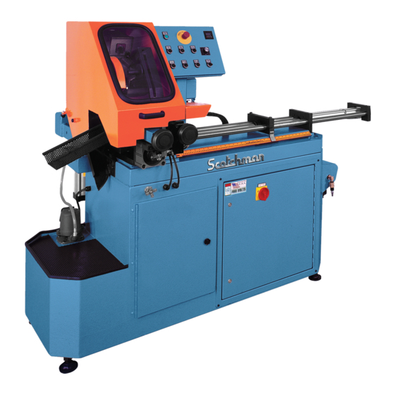
Summary of Contents for Scotchman CPO-315-HFA-5HP
- Page 1 You have downloaded a manual for our MODEL CPO-315-HFA-5HP COLD SAW Please download our Cold Sawing Guide too. Read both the manual and guide before operating this saw!!
- Page 2 MODEL CPO-315-HFA-5HP COLD SAW PRINTED MAY 2021 SCOTCHMAN IND. - 180 E US HWY 14 - PO BOX 850 - PHILIP, SD 57567 Call: 1-605-859-2542...
-
Page 3: Table Of Contents
TABLE OF CONTENTS SECTION DESCRIPTION PAGE # INTRODUCTION SAFETY PRECAUTIONS WARRANTY INSTALLATION & SET-UP Physical Dimensions Machine Installation Electrical Requirements Coolant System MACHINE START-UP Control Panel Functions MACHINE OPERATION Selecting The Proper Blade and Cutting Speed Blade Installation Saw Capacities Main Vise Shuttle Vise Power Down Feed... -
Page 4: Description Page
TABLE OF CONTENTS SECTION DESCRIPTION PAGE # OPTIONAL EQUIPMENT Special Vise Jaws Optional In Feed Supply Tracks 10.0 TROUBLE SHOOTING GUIDE 10.1 Electrical Trouble Shooting 10.2 Breakage or Excessive Dulling of Blades 10.3 Part Length Is Not Consistent 10.4 Coolant System 10.5 PLC (LED’s) 10.6... -
Page 5: Introduction
1.0 INTRODUCTION The CPO-315 HFA Fully Automatic Cold Saw is designed to cut solids, tubes, flats and other profiles in grades of material that range from hot and cold rolled steel, annealed tool steels, stainless, aluminum, brass, copper, synthetics and extrusions. Cold sawing is a process similar to a milling process. -
Page 6: Warranty
3.0 WARRANTY Scotchman Industries, Inc. will, within 2 years of date of purchase, replace F.O.B. the factory or refund the purchase price for any goods which are defective in materials or workmanship, provided that the buyer returns the warranty registration card within thirty (30) days of purchase date and, at the seller’s... -
Page 7: Installation & Set-Up
4.0 INSTALLATION AND SET-UP CAUTION: THIS SECTION DISCUSSES INSTALLATION AND SET-UP PROCEDURES. PLEASE READ ALL SECTIONS OF THIS MANUAL THOROUGHLY BEFORE OPERATING THIS MACHINE. 4.1 PHYSICAL DIMENSIONS SEE FIGURE 1 ON THE FOLLOWING PAGE. DIMENSIONS INCHES HEIGHT FLOOR TO VISE 38.5 BASE HEIGHT VISE OPENING... - Page 8 FIGURE 1 Page 7...
-
Page 9: Machine Installation
4.2 MACHINE INSTALLATION SEE FIGURE 2 ON THE FOLLOWING PAGE. This machine is shipped on a pallet and can be moved to the installation location by means of a forklift. CAUTION: THIS MACHINE IS TOP HEAVY AND MUST BE MOVED WITH CARE, ON HARD FLAT SURFACES ONLY. - Page 10 FIGURE 2 Page 9...
-
Page 11: Electrical Requirements
4.3 ELECTRICAL REQUIREMENTS CAUTION: TO PREVENT DAMAGE TO THE MACHINE AND DANGER TO THE OPERATOR, ALL ELECTRICAL CONNECTIONS MUST BE MADE BY A QUALIFIED ELECTRICIAN. THIS MACHINE OPERATES WITH LIQUID COOLANT AND MUST BE GROUNDED IN ACCORDANCE WITH NATIONAL ELECTRIC CODES. All machines are wired for three phase power. -
Page 12: Coolant System
4.4 COOLANT SYSTEM The CPO-315-HFA saw is equipped with a mist coolant system. A flood coolant system is an option for this saw. The container for the coolant is located on the inside of the front door of the saw. The coolant should be mixed in a ratio of one part coolant to seven parts water. -
Page 13: Machine Start-Up
5.1 CONTROL PANEL FUNCTIONS The following section gives a brief description of each of the control panel switches and buttons. Before powering the machine, please familiarize yourself with the location and the function of each of these items. SECTION 7.0 will describe how to set the machine up for an operation. SEE FIGURE 3 BELOW. - Page 14 5.1A MAIN POWER SWITCH This is the main power disconnect switch for the machine and it should be locked or tagged in the OFF position any time that maintenance or service work is being performed. Maintenance or service work on the electrical controls must be performed by qualified personnel.
- Page 15 5.1E HEAD UP This button is used to abort a cut in mid cycle when the AUTOMATIC/MANUAL SWITCH is in the MANUAL position. This button is inoperable when the machine is in the AUTOMATIC position. 5.1F HEAD DOWN This button is also used to set the overall stroke of the machine and to make manual cuts. 5.1G HITCH SELECTOR This switch is used to select the number of hitches the shuttle vise makes before the saw makes a cut.
- Page 16 5.1J TRIM/TEST This button is used to do first part cuts prior to running the machine in the automatic position. With the AUTO/MANUAL switch in the MANUAL position, press the TRIM/TEST button (J) and then, press the CYCLE button (H). The saw will trim and then cut one part and return to the up position. Make whatever adjustments that you need to and depress the CYCLE button (H) again and the saw will cut one more test piece.
-
Page 17: Machine Operation
5.1N FEED RATE CONTROL This valve controls the down feed rate of the saw head and is used in the set-up of the up and down stroke control of the saw head. To adjust the down feed cutting rate of the head, turn the control all the way to the right (clockwise) and then, open it one turn. - Page 18 THIS PAGE LEFT BLANK INTENTIONALLY. Page 17...
-
Page 19: Blade Installation
6.2 BLADE INSTALLATION SEE FIGURE 4 BELOW. FIGURE 4 Page 18... - Page 20 CAUTION: USE ONLY HIGH SPEED STEEL BLADES DESIGNED FOR THIS MACHINE. DO NOT MODIFY ANY BLADE TO FIT THIS MACHINE. DO NOT USE BLADES DESIGNED FOR THIS MACHINE ON ANY OTHER EQUIPMENT. THE MAXIMUM RPM’S FOR THESE BLADES ARE 600 FOR THE 12-1/2" AND 700 FOR THE 10-3/4". The CPO-315-HFA saw is designed to use a maximum 12-1/2 inch (315mm) diameter blade.
- Page 21 Adjust the blade guide bolts (G), if required. These guides are required only when the blade has a small amount of deflection in it or when a very exact cut is required. Adjust the inside, or right hand bolt, first. The bolt should be adjusted up to where it just touches the blade as close to the teeth as possible and lock the retaining nut.
-
Page 22: Saw Capacities
6.3 SAW CAPACITIES SEE FIGURE 5 BELOW. Figure 5 below is a chart showing the maximum capacities of this machine in various materials. RFA/ST RFA/ST CAPACITIES WITH MAXIMUM DIAMETER 90° ONLY 90° ONLY BUNDLE FEED BLADES 315 MM INCHES Ø3-1/2 Ø3 Ø3 Ø89... -
Page 23: Main Vise
6.4 MATERIAL MAIN VISE SEE FIGURE 6 BELOW. FIGURE 6 Page 22... - Page 24 The following are set-up and maintenance instructions for the material main vise. Make sure that the filter/lubricating device (A) is full of oil. NOTE: Use a quality (ISO 22) air line lubricant designed for automatic oilers. Slide the shuttle valve (F) on the filter/lubricator device down to the closed position. Connect the air supply to the shuttle valve.
- Page 25 FIGURE 7 Page 24...
-
Page 26: Shuttle Vise
6.5 SHUTTLE VISE & CYLINDER REFER TO FIGURE 6 ON PAGE 22. CAUTION: ALWAYS DISCONNECT THE AIR SUPPLY BEFORE REMOVING THE FILLER PLUG FROM THE RESERVOIR. IF THE FILLER PLUG IS REMOVED WHILE THE MACHINE IS CONNECTED TO AIR PRESSURE, THE FLUID IN THE TANK WILL BE PURGED THROUGH THE OPENING UNDER PRESSURE. -
Page 27: Power Down Feed
6.6 POWER DOWN FEED REFER TO FIGURE 8 BELOW. FIGURE 8 Page 26... - Page 28 CAUTION: ALWAYS DISCONNECT THE AIR SUPPLY BEFORE REMOVING THE FILLER PLUG FROM THE RESERVOIR. IF THE FILLER PLUG IS REMOVED WHILE THE MACHINE IS CONNECTED TO AIR PRESSURE, THE FLUID IN THE TANK WILL BE PURGED THROUGH THE OPENING UNDER PRESSURE. BEFORE POWERING THE SAW, check the oil level in the reservoir (A).
-
Page 29: Material Clamping
6.7 MATERIAL CLAMPING All work pieces must be clamped securely in the vise. Any slippage of the material can result in broken or damaged blades. The material should be clamped so that the contact surface between the material and the blade is as small as possible. For this reason, when cutting flat stock material, we recommend standing it up and cutting it through the thinnest section, whenever possible. - Page 30 FIGURE 9 Page 29...
-
Page 31: Counter Set-Up
6.9 COUNTER SET-UP REFER TO FIGURE 10 BELOW. FIGURE 10 Page 30... - Page 32 A. PARTS COUNTER The Parts Counter is programmed at the factory to count up. If you want to set the counter to count down, please contact the factory. To enter a pre-set value in the counter, press any of the white keys numbered 1to 5.
-
Page 33: Machine Automatic Operation (Set-Up)
7.0 MACHINE AUTOMATIC OPERATION (SET-UP) REFER TO FIGURE 11 BELOW. The following instructions are to set up a job for automatic operation. Make sure that you are familiar with the functions of all of the switches and buttons before proceeding. FIGURE 11 Page 32... - Page 34 Set the shuttle vise indicator to the desired length by loosening the moving stop (M) and move it to the length desired on the scale and re-tighten it. These bolts must be locked down tight, to prevent the length setting from changing while the saw is in operation. Check them periodically throughout the day.
-
Page 35: Maintenance
8.0 MAINTENANCE 8.1 LUBRICATION SEE FIGURE 12 BELOW. Grease the head pivot pin (C) and the spindle shaft with a high pressure, high temperature, bearing grease daily. Apply oil to the shuttle vise guide shafts daily. Clean the chips out of the vise at least once a day, more often if needed. Apply penetrating oil to the spindle and guide pins. -
Page 36: Cutting Oils And Lubricants
8.2 CUTTING OILS AND LUBRICANTS SECTION 12.2 lists Scotchman.s parts numbers for cutting oils and lubricants. Using high quality lubricants and oils will greatly increase the life of this equipment. We recommend using only pure, synthetic, water soluble, cutting oil for coolant. -
Page 37: Gear Replacement (Saw Head)
8.4 GEAR REPLACEMENT (SAW HEAD) REFER TO FIGURE 13 BELOW. FIGURE 13 Page 36... - Page 38 Remove the drain plug (A) from the head casting and allow the fluid to drain. Remove the motor from the head. Remove the four bolts (E) from the bearing retainer (F). Remove the worm shaft assembly (J). The worm shaft has a 10mm threaded hole in the end of it for a slide hammer.
-
Page 39: Spindle Replacement (Main Vise)
8.5 SPINDLE REPLACEMENT (MAIN VISE) SEE FIGURE 14 BELOW. FIGURE 14 Page 38... -
Page 40: Seal Replacement (Main Vise)
Disconnect the machine’s power and the air supply. Remove the spindle shield (XX) and the spring (Y) and ball (HH). Remove the bolts (A & B) and the retainer (D). Remove the clevis pin (F) and remove the clevis (E) and the forks (CC). The spindle can now be removed from the machine. -
Page 41: Shuttle Vise Maintenance
8.7 SHUTTLE VISE MAINTENANCE SEE FIGURE 15 BELOW. FIGURE 15 Page 40... - Page 42 TO REPLACE THE VISE SPINDLE: Remove the jam nut (GG), the set screw (H), the spring (FF) and the ball (G). Remove the jam nut (A) and the boss (B) from the end of the spindle. Disconnect the air lines and the proximity switch from the cylinder. The air connections on the cylinder are snap connectors.
-
Page 43: Coolant Pump Maintenance
8.8 COOLANT PUMP MAINTENANCE (OPTINAL FLOOD COOLANT) SEE FIGURE 16 BELOW. FIGURE 16 Page 42... - Page 44 IF YOUR COOLANT PUMP IS LEAKING OR LACKS POWER, USE THE FOLLOWING STEPS: NOTE: WE RECOMMEND REPLACING THE PUMP SEAL ANYTIME THE PUMP IS DISMANTLED. A SEAL KIT IS AVAILABLE. FOR PART NUMBER IDENTIFICATION, REFER TO SECTION 11.13. Make sure that the power to the machine is off. Remove the four bolts (J) and remove the pump from the machine.
-
Page 45: Optional Equipment
9.0 OPTIONAL EQUIPMENT 9.1 SPECIAL VISE JAWS Special vise jaws for holding thin wall round tubes, profiles and bundles are available on a made-to-order basis. For prices and delivery on special jaws, contact your local dealer or the factory. For examples, REFER TO FIGURE 7 ON PAGE 24. - Page 46 FIGURE 17 Page 45...
-
Page 47: Trouble Shooting Guide
10.0 TROUBLE SHOOTING GUIDE 10.1 ELECTRICAL TROUBLE SHOOTING THE MOTOR WILL NOT RUN. The main disconnect switch in the base cabinet must be on and the emergency stop switch must be pulled out. The motor switch must be in the ON position to start the saw motor. The MANUAL/AUTO switch must be in the MANUAL position to start the machine. -
Page 48: Part Length Is Not Consistent
Have your blades re-sharpened by someone who has the right equipment for circular cold saw blades. Improper re-sharpening is one of the most common problems encountered in cold sawing. Keep the blade flange, the face of the blade spindle and the blade clean and free from nicks. Any contamination or nicks on the flange, spindle or the blade will cause the blade to run out of alignment. -
Page 49: Plc (Led's)
10.5 PLC TROUBLESHOOTING SEE FIGURE 18 ON THE FOLLOWING PAGE. The PLC on this machine has a readable screen on it that can be used to diagnose most problems that you may encounter with the machine. The main controller has 12 inputs numbered I-1 to I-12 and six outputs numbered Q-1 through Q-6. - Page 50 RUNNING SEQUENCE INITIAL START UP E-STOP PULLED OUT POWER UP PUSHED (Turning Power ON) I - 3, 4 R - 7 I - 1, 3, 4 R - 7 I - 3, 4 R - 7 Q - 4 S - none Q - 4 S - none Q - 4...
-
Page 51: Pneumatic System
10.6 PNEUMATIC SYSTEM REFER TO FIGURE 19 BELOW. 1A - 5/16" BLACK TO SAW VISE BACK 1B - 5/16" BLACK TO SAW VISE FRONT 2A - 1/4" RED TO TOP OF POWER DOWN HYD. TANK 2B - 1/4" GREEN TO BOTTOM OF POWER DOWN CYLINDER 3A - 1/4"... - Page 52 THE MOST COMMON PNEUMATIC/HYDRAULIC PROBLEMS ARE: Low levels of fluid in the reservoirs. The fluid level in the power down feed reservoir should be approximately 1-1/2 inches below the top of the reservoir with the head in the down position and 2-1/2 inches below the top of the reservoir when the head is in the up position.
-
Page 53: Parts Lists
11.0 PARTS LISTS THE FOLLOWING SECTIONS CONTAIN THE SAW AND OPTIONAL EQUIPMENT PARTS LISTS AND DRAWINGS FOR YOUR CONVENIENCE, ALWAYS GIVE YOUR COMPLETE SERIAL NUMBER WHEN ORDERING PARTS! 11.1 SAW HEAD ITEM PART # DESCRIPTION 077150 Needle Bearing 077322 Worm Shaft 077323 Pivot Bearing 077324... - Page 54 075081 O-Ring 045327 Straps 201120 M-6 x 20 HHCS 201135 M-6 x 35 HHCS 154004 Rivet 077630 Vent 045382 Complete Head Assembly FIGURE 20 Page 53...
-
Page 55: Main Vise Assembly
11.2 MAIN VISE ASSEMBLY ITEM PART # DESCRIPTION 221245 10 x 160mm SHCS 221240 10 x 140mm SHCS 221235 10 x 100mm SHCS 045311 Clevis Guide 045312 Clevis 045317 Clevis Pin 046655 Snap Ring 045630 Cylinder 045631 Cylinder Seal Kit 045313 Cylinder Mount 045301... - Page 56 219047 M-10 x 12 Set Screw 077798 Vise Jaws 203212 M-10 x 30 HHCS 045224 Clevis Wear Plate 045329 Angle Shelf 073626 M-10 x 20 SHCS 114020 Washer 060270 End Cap 210012 M-10 Jam Nut 045300 Complete Vise Assembly FIGURE 21 Page 55...
-
Page 57: Shuttle Vise Assembly
11.3 SHUTTLE VISE ASSEMBLY ITEM PART # DESCRIPTION 111015 5/8 x 11 Jam Nut 045219 Boss 045652 Cylinder Body 045662 Cylinder Rebuild Kit - Shuttle Vise 045220 Cylinder Mounting Plate 077743 Fitting 045221 Detent Block 046652 Detent Ball 218048 M-10 Set Screw 220027 M-8 x 35 RHMS 201160... -
Page 59: Shuttle Assembly
11.4 SHUTTLE ASSEMBLY ITEM PART # DESCRIPTION 077742 1/4 Inch NPT x 169 Plastic 077701 Filter 077777 3/8 NPT Filler Plug 3/8 Inch NPT Nipple 077774 077712 Flow Control Valve 045042 1168 x 1/2 Male Connector 045048 Line (Cylinder 1/2) 060501 Line (Valve 5/16) 077738... - Page 60 045201 Rear Plate 045284 Reservoir 045197 Adjustable Wear Plate 230207 M-10 x 20 FSHCS 218000 M-8 x 8 Set Screw 045254 Roller 221212 M-10 x 30 SHCS 045259 Roller Block 221210 M-10 x 25SHCS FIGURE 22 Page 59...
-
Page 61: Fine Adjustment Stop Assembly
11.5 FINE ADJUSTMENT STOP ASSEMBLY ITEM PART # DESCRIPTION 045205 Fine Adjustment 045206 Adjustment Collar 016063 1-1/2 Snap Ring 046652 Detent Ball 045602 Detent Spring 045204 Sliding Stop 204225 M-10 x 60 HHCS 221212 M-10 x 30 SHCS 045259 Roller Block 045254 Roller 114020... - Page 62 FIGURE 24 Page 61...
-
Page 63: Power Down Feed Assembly
11.6 POWER DOWN FEED ASSEMBLY ITEM PART # DESCRIPTION 045590 Power Down Feed Cylinder 045641 Rod Seal Kit 045591 Piston Seal Kit 045425 Reservoir 077715 Pivot Bolt 045232 Cylinder Bracket 116012 3/8 Nylon Lock Nut 077746 1/4" NPT x 169 Plastic 221210 M-10 x 25 SHCS 045230... - Page 64 FIGURE 25 Page 63...
-
Page 65: A Power Down Feed Valves
11.6A POWER DOWN FEED VALVES ITEM PART # DESCRIPTION 077746 1/4" NPT x 169 PL 077701 Baffle 077777 3/8" NPT Plug 045054 Ninety Degree Swivel 077536 Check Valve 045042 Return Line Fitting G-H-I MVK6 Mounting Kit 047535 Flow Control Valve 045054 1/4 NPT x 1/2 PL Ninety Degree Swivel 045041... - Page 66 FIGURE 26 Page 65...
-
Page 67: B Power Down Feed Air Controls
11.6B AIR CONTROLS ITEM PART # DESCRIPTION Provided by Customer 077719 Shuttle Valve 077737 1/4 NPT Brass Street Elbow 077780 Brass NPT Coupler 077779 1/4" NPT Nipple 045604 Complete Filter/Regulator/Lubricator 045605 Mounting Brackets 077738 90 Degree Fitting 045609 Replacement Bowls 045610 Filter Seal Kit 045612... - Page 68 FIGURE 27 Page 67...
-
Page 69: Air Valve Assembly
11.7 AIR VALVE ASSEMBLY ITEM PART # DESCRIPTION 046047 Cable End 077744 Fitting (5/16 PL To 1/4 NPT) 077777 Plug (3/8 NPT) 077740 Ninety Degree Elbow 045650 Solenoid 045655 Valve 677728 Fitting (1/4 NPT To 1/4 PL) 045653 Complete Valve Assembly 045655 Valve with Solenoid Page 68... - Page 70 FIGURE 28 Page 69...
-
Page 71: Blade Guard Assembly
11.8 BLADE GUARD ASSEMBLY ITEM PART # DESCRIPTION 045267 Guard Shell 073641 M-10 SHCS 040087 M-10 Brass HHCS 208012 M-10 Jam Nut 026621 M-10 Tee Nut 073766 Coolant Line 046269 Hose Barb 073450 M-4 x 16 SHCS 076839 Mister Unit (Optional) (Includes J, K &... - Page 72 FIGURE 29 Page 71...
-
Page 73: Motor Assembly
11.9 MOTOR ASSEMBLY ITEM PART # DESCRIPTION 046358 Angled Fan Cover 073407 M-5 x 8 SHCS End Casting 077325 Motor Bearing Snap Ring 076369 203210 M-10 SHCS 077370 Key 6 x 4 x 32mm Seal Spacer Washer Snap Ring (30mm Only) End Casting (Front) 077375 Pinion Gear... - Page 74 FIGURE 30 Page 73...
-
Page 75: Electrical Unit-Line Circuit
11.10 ELECTRICAL UNIT - LINE CIRCUIT ITEM PART # DESCRIPTION 011854 Disconnect Switch 048010 KM/AFR Primary Fuse 1/2 AMP 011930* Transformer 150VA - Replacement FNM-2 - Grainger # 4XC10 048030 KM 24VDC Power Supply 000940 Motor Protect Switch (6-10 Amp) Motor Protect Switch (1.6 Amp) 049375 (Optional Flood Coolant Pump) - Page 76 FIGURE 31 Scotchman Inds. PART NO. Page 75 045345...
- Page 78 FIGURE 31B Page 77...
-
Page 79: Base Assembly
11.12 BASE ASSEMBLY ITEM PART # DESCRIPTION 045171 Base Cabinet 045413 Base Casting 045735 Lower Enclosure 046642 Door Assembly 045257 Reservoir Screen 060150 230 Volt Coolant Pump 060158 460 Volt Coolant Pump 060160 575 Volt Coolant Pump 049217 Leveling Pads 208024 M-24 Hex Nut 073350... - Page 80 FIGURE 32 Page 79...
-
Page 81: Coolant Pump
11.13 COOLANT PUMP ITEM PART # DESCRIPTION 060150 230 Volt Coolant Pump 060158 460 Volt Coolant Pump 060160 575 Volt Coolant Pump 060152 Impeller 060151 Seal Kit Bolt Bolt 060080 90 Degree Elbow 060140 Coolant Line 060095 Pump Cable 221005 M-6 x 12 SHCS 049335 Valve Assembly... - Page 82 FIGURE 33 Page 81...
- Page 84 FIGURE 34 Page 83...
-
Page 85: Hood Assembly
11.15 HOOD ASSEMBLY ITEM PART # DESCRIPTION 203217 M-10 x 45 HHCS 045196 Pedestal 045285 Pivot Pin 046018 Hood Handle 045464 Extension 045322 Sight Glass 046645 Sight Glass Seal 201120 M-6 x 20 HHCS 077157 M-6 Nylon Loc Nut 229415 M-10 x 12 x 16 Shoulder Bolt 045255 Hood... - Page 86 FIGURE 35 Page 85...
-
Page 87: Optional Equipment Parts Lists
12.0 OPTIONAL EQUIPMENT PARTS LISTS 12.1 TEN FOOT (304 CM) SUPPLY TRACK ITEM PART # DESCRIPTION 029243 Conveyor Assembly 029244 Leg Assembly 029245 Roller 221210 M-10 x 25 HHCS 076935 Optional Guide Assembly 076942 Material Guide Base 229225 M-10 x 70 Shoulder Bolt 043003 Guide Roller 214012... - Page 88 FIGURE 36 Page 87...
-
Page 89: Cutting Coolants And Lubricants
12.2 CUTTING COOLANTS AND LUBRICANTS ITEM PART # DESCRIPTION 1 Gal. 075751 1 GA. SAW COOLANT 5 Gal. 075752 5 GA. SAW COOLANT 55 GAL. SAWING COOLANT 55 Gal. 075754 1 Gal. 075756 1 GAL. STAINLESS COOLANT 5 Gal. 075757 5 GAL. - Page 90 FIGURE 36 Page 89...
-
Page 91: Shuttle Vise Pressure Regulator
12.4 SHUTTLE VISE REGULATOR ITEM PART # DESCRIPTION 078190 Regulator 677934 Regulator Mount 077864 M-5 x 12 SHCS 077746 1/4" x 90 Degree Swivel Fitting 077721 Bushing 077750 Nipple Page 90... - Page 92 FIGURE 38 Page 91...
-
Page 93: Safety Valve / Solenoid
13.0 SAFETY VALVE / SOLENOID SAW BASE SAFETY VALVE / SOLENOID LOCATION SAFETY VALVE / SOLENOID DETAIL PARTS LIST ITEM PART # DESCRIPTION 201135 M6 X 35MM HHCS 073206 M6 HEX NUT 3/8" 90° MALE SWIVEL 077740 045030 1169X5X6SZ ELBOW 90° MALE 044110 24V AIR VALVE Page 92... -
Page 94: Wiring Diagrams
14.0 WIRING DIAGRAMS Scotchman Inds. PART NO. Page 93 045345... - Page 95 Scotchman Inds. PART NO. Page 94 045345...
- Page 96 Part Prev. Page Cont. Next Page Cont. Next Page Part Scotchman Inds. Prev. Page PART NO. Page 95 045345...
- Page 97 Cont. Prev. Page Cont. Prev. Page Scotchman Inds. PART NO. Page 96 045345...
-
Page 98: Stock Blades
15.0 STOCK BLADES 315 MM (12-1/2 Inch) x 40 Bore (Pin Spacing 2/8/55 & 4/12/64) ITEM PART # DESCRIPTION 074355 90 Tooth 12-1/2" (315mm) Dia. 074356 100 Tooth 12-1/2" (315mm) Dia. 074357 110 Tooth 12-1/2" (315mm) Dia 120 Tooth 12-1/2" (315mm) Dia. 074345 074348 150 Tooth 12-1/2"... - Page 99 275 MM (10-3/4 Inch) x 40 Bore (Pin Spacing 2/8/55 & 4/12/64) ITEM PART # DESCRIPTION 90 Tooth 10-3/4" (275mm) Dia. 074360 074361 100 Tooth 10-3/4" (275mm) Dia. 120 Tooth 10-3/4" (275mm) Dia. 074362 150 Tooth 10-3/4" (275mm) Dia. 074363 180 Tooth 10-3/4"...
Need help?
Do you have a question about the CPO-315-HFA-5HP and is the answer not in the manual?
Questions and answers