
Related Manuals for Scotchman CPO-350-NF-5HP


Summary of Contents for Scotchman CPO-350-NF-5HP
- Page 1 You have downloaded a manual for our MODEL CPO-350-NF SAW Please read this Manual before operating this saw!!
- Page 2 MODEL CPO-350-NF-5HP COLD SAW S/N B2153NF & After Printed May 2021 SCOTCHMAN INDS. - 180 E US HWY 14 - PO BOX 850 - PHILIP, SD 57567 Phone: 1-800-843-8844...
-
Page 3: Table Of Contents
TABLE OF CONTENTS SECTION DESCRIPTION PAGE # INTRODUCTION SAFETY PRECAUTIONS WARRANTY INSTALLATION & SET-UP 8-16 Physical Dimensions Machine Moving Procedure 10-11 Physical Inspection Electrical Requirements 12-14 Machine Start-up Guard Adjustment 16-17 Coolant System MAINTENANCE & LUBRICATION 18-21 Lubrication 18-19 Cutting Oils & Lubricants Scheduled Maintenance MACHINE OPERATION 22-29... - Page 4 TABLE OF CONTENTS SECTION DESCRIPTION PAGE # OPTIONAL EQUIPMENT 30-48 Power Vise 7.1A Power Vise Set-up & Maintenance 30-31 7.1B Replacing the Spindle-Power Vise 32-33 7.1C Replacing the Seals-Power Vise 34-35 Power Down Feed 7.2A Power Down Feed Set-up & Maintenance 36-37 7.2B Stroke Control Adjustment-Power Down Feed...
- Page 5 TABLE OF CONTENTS SECTION DESCRIPTION PAGE # PARTS LISTS 54-69 Drive Assembly 54-55 Vise Assembly 56-57 Guard Assembly 58-59 Motor Assembly 60-61 Electrical 62-63 Coolant System & Base 64-65 Cast Base & Pedestal 66-67 Material Stop 30 Inch (76 cm) 68-69 10.0 OPTIONAL EQUIPMENT PARTS LISTS...
-
Page 6: Introduction
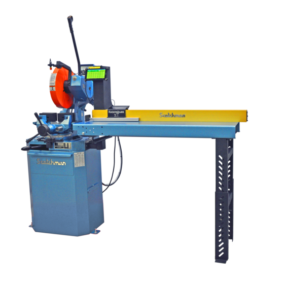
1.0 INTRODUCTION The CPO 350-NF Cold Saw is a high speed saw designed to cut solids, tubes, flats and other profiles in grades of nonferrous material that range from aluminum, brass, copper, synthetics and extrusions. Cold sawing is a process similar to a milling process. In most cases, this, combined with the self centering vise feature, gives a finished cut that does not require any secondary machining or de-burring. -
Page 7: Safety Precautions
2.0 SAFETY PRECAUTIONS Any individual operating this machine must be qualified, responsible and well instructed. THIS MANUAL IS NOT INTENDED TO TEACH UNTRAINED PERSONNEL HOW TO OPERATE EQUIPMENT. Never operate this machine with the blade guard removed or disconnected. This machine is designed for nonferrous material only. -
Page 8: Warranty
3.0 WARRANTY Scotchman Industries, Inc. will, within three years of the date of purchase, replace F.O.B. the factory or refund the purchase price for any goods which are defective in materials or workmanship, provided the buyer, at the seller’s option, returns the defective goods freight and delivery prepaid to the seller, which shall be the buyer’s sole and exclusive remedy for defective goods. -
Page 9: Installation & Set-Up
4.0 INSTALLATION AND SET-UP CAUTION: THIS SECTION DISCUSSES INSTALLATION, SET-UP AND START-UP PROCEDURES. PLEASE READ IT THOROUGHLY BEFORE OPERATING THIS MACHINE. IF YOUR MACHINE IS EQUIPPED WITH EITHER THE POWER VISE OR THE POWER DOWN FEED OPTION, READ ALL SECTIONS CONCERNING THESE OPTIONS BEFORE OPERATING THE SAW. - Page 10 VISE VISE FIGURE 1 FIGURE 1 Page 9...
-
Page 11: Machine Moving Procedure
4.2 MACHINE MOVING PROCEDURES SEE FIGURE 2 BELOW. FIGURE 2 Page 10... -
Page 12: Physical Inspection
This machine is shipped on a pallet and can be moved to the installation location by means of a fork lift. CAUTION: THIS MACHINE IS TOP HEAVY AND MUST BE MOVED WITH CARE, ON HARD FLAT SURFACES ONLY. All saws, except models equipped with the power down feed option, are shipped with the head locked in the DOWN position. -
Page 13: Electrical Requirements
4.4 ELECTRICAL REQUIREMENTS SEE FIGURE 3A BELOW & 3B ON THE FOLLOWING PAGE. CPO 350 NF AND CPO 350 NF/PK FIGURE 3A Page 12... - Page 14 CPO 350 NF/PK/PD FIGURE 3B Page 13...
- Page 15 CAUTION: TO PREVENT DAMAGE TO THE MACHINE AND DANGER TO THE OPERATOR, ALL ELECTRICAL CONNECTIONS SHOULD BE MADE BY A QUALIFIED ELECTRICIAN. THIS MACHINE OPERATES WITH LIQUID COOLANT AND MUST BE GROUNDED IN ACCORDANCE WITH NATIONAL ELECTRIC CODES. All machines are wired for three phase power. The motors are single voltage, 230 or 460, and will operate on one voltage only.
-
Page 16: Machine Start-Up
On machines equipped with either a power vise or a power down feed, the air supply must also be disconnected and locked or tagged. Scotchman offers a lock-out switch for this machine as an option, if your plant is not equipped with lock-out capabilities. If you are interested in this option, REFER TO SECTION 7.6 or contact your local dealer or the factory. -
Page 17: Guard Adjustment
4.6 GUARD ADJUSTMENT-MANUAL MACHINES SEE FIGURE 4 ON THE FOLLOWING PAGE. FOR GUARD ADJUSTMENT PROCEDURES ON SAWS EQUIPPED WITH THE POWER DOWN FEED OPTION, REFER TO SECTION 7.2. The proper adjustment of the blade guard on this machine is crucial to the operation of the machine and the safety of the operator. - Page 18 FIGURE 4 FIGURE 5 Page 17...
-
Page 19: Maintenance & Lubrication
5.0 MAINTENANCE AND LUBRICATION 5.1 LUBRICATION SEE FIGURE 6 ON THE FOLLOWING PAGE. Before operating the saw, grease the pivot pin (A) and the spindle shaft (D) with a high pressure, high temperature bearing grease. Apply penetrating oil to the vise spindle and guides (B and C). Once a week, grease all of the pivot pins and oil all of the rivet connections on the guard linkage. - Page 20 FIGURE 6 Page 19...
-
Page 21: Cutting Oils & Lubricants
5.2 CUTTING OILS AND LUBRICANTS SECTION 10.6 lists Scotchman’s parts numbers for cutting oils and lubricants. Using high quality lubricants and oils will greatly increase the life of this equipment. Use only P/N 075760, (SYNCON-2) mixed in a ratio of one part coolant to seven parts water. -
Page 22: Scheduled Maintenance
5.3 SCHEDULED MAINTENANCE A program of scheduled maintenance should be set up and documented according to your application and the frequency you use this machine. The following is a list of some important things that should be included in a scheduled maintenance program: EVERY 250 HOURS OR 3 MONTHS: Check the condition of the drive belt. -
Page 23: Machine Operation
6.0 MACHINE OPERATION 6.1 INSTALLING BLADES-MANUAL MACHINES SEE FIGURE 7 BELOW. FIGURE 7 Page 22... - Page 24 REFER TO SECTION 7.2D FOR INSTALLING BLADES ON MACHINES EQUIPPED WITH THE POWER DOWN FEED OPTION. CAUTION: THIS MACHINE IS DESIGNED TO USE CARBIDE TIPPED BLADES ONLY. USE ONLY BLADES DESIGNED FOR THIS MACHINE. DO NOT MODIFY ANY BLADE TO FIT THIS MACHINE.
-
Page 25: Saw Capacities
6.2 SAW CAPACITIES CPO - 350 - NF #060332 03/21 90° 45° CAPACITIES WITH MAXIMUM DIAMETER BLADES 350 MM INCHES Ø4-1/2 Ø4-1/4 Ø114 Ø108 INCHES 4-1/4 X 4-1/4 4 X 4 108 X 108 102 X 102 INCHES 4-1/4 X 4-1/4 4 X 4 108 X 108 102 X 102... -
Page 26: Selecting The Proper Cutting Speed
6.3 SELECTING THE PROPER CUTTING SPEED THE CHART BELOW gives the surface feet per minute for the various diameter blades: BLADE DIAMETER SURFACE FEET PER MINUTE INCH 3,000 RPM’S 9,800 13.5 11,000 Page 25... -
Page 27: Material Clamping
6.4 MATERIAL CLAMPING All work pieces must be clamped securely in the vise. Any slippage of the material can result in broken or damaged blades. The material should be clamped so that the contact surface between the material and the blade is as small as possible. - Page 28 FIGURE 9 FIGURE 10 Page 27...
-
Page 29: Miter Locking Device
6.5 MITER LOCKING DEVICE SEE FIGURE 11 ON THE FOLLOWING PAGE. All models manufactured for domestic sales are equipped with a miter locking device which allows quick set-up for mitering at 45 degrees left and right and 90 degrees for straight cutting. A miter locking device is available as an option for models manufactured for international sales. - Page 30 FIGURE 11 Page 29...
-
Page 31: Optional Equipment
7.0 OPTIONAL EQUIPMENT 7.1 POWER VISE The power vise is an option that is normally ordered with the saw. A retrofit kit is available from your local dealer or the factory. The kit includes all parts required, plus complete installation instructions. The power vise allows automatic clamping of the material, which improves productivity and reduces operator fatigue. - Page 32 TO ADJUST THE VISE TO THE SIZE OF MATERIAL BEING CUT: Release the locking collar (D) on the vise spindle. The vise spindle is left hand threaded and the locking collar must be turned clockwise to release it. Open the vise, using the positioning handle (E), and place the material in the vise. Crank the vise closed to within approximately 1/8 of an inch (3mm) from the material and re-lock the locking collar (D).
-
Page 33: B Replacing The Spindle-Power Vise
7.1B REPLACING THE SPINDLE IN THE AIR VISE SEE FIGURE 13 ON THE FOLLOWING PAGE. Disconnect the machine’s power and air supply. Remove the air lines (A) from the front of the cylinder. Remove the support block (B) and the bolts (C) from the base of the vise. Remove the guide pins (D) out through the back of the vise. - Page 34 FIGURE 13 Page 33...
-
Page 35: C Replacing The Seals-Power Vise
7.1C REPLACING THE SEALS IN THE AIR VISE SEE FIGURE 14 ON FOLLOWING PAGE. Open the vise to its full open position. Disconnect the air lines from the cylinder. Remove the jam nut (G), the hand wheel (B) and the locking collar (C) from the front of the spindle. - Page 36 FIGURE 14 Page 35...
-
Page 37: Power Down Feed
7.2 POWER DOWN FEED The power down feed option, used in conjunction with the power vise option, changes a manual saw into a semi-automatic saw. These options will increase productivity and reduce operator fatigue. The power down feed option cannot be retrofit to machines with serial number 11940491 and prior in the field. - Page 38 FIGURE 15 Page 37...
-
Page 39: B Stroke Control Adjustment-Power Down Feed
7.2B STROKE CONTROL ADJUSTMENT (POWER DOWN FEED) SEE FIGURE 16 ON THE FOLLOWING PAGE. Before powering the machine, the up and down stroke of the saw head must be set. The stroke is set by the collars (A & B) on the shaft (C). TO SET THE STROKE: Without powering the saw, cycle the head down by depressing the foot switch. - Page 40 FIGURE 16 Page 39...
-
Page 41: C Guard Adjustment-Power Down Feed
7.2C GUARD ADJUSTMENT (POWER DOWN FEED) SEE FIGURE 17 ON THE FOLLOWING PAGE. CAUTION: THE GUARD MUST BE ADJUSTED EVERY TIME THAT THE STROKE OF THE MACHINE IS ADJUSTED. TO ADJUST THE GUARD: Before adjusting the guard, set the up and down stroke of the machine, following the instructions in SECTION 7.2B. - Page 42 FIGURE 17 Page 41...
-
Page 43: D Installing Blades-Power Down Feed
7.2D INSTALLING BLADES (POWER DOWN FEED) SEE FIGURE 18 ON THE FOLLOWING PAGE. CAUTION: USE ONLY BLADES DESIGNED FOR THIS MACHINE. DO NOT MODIFY ANY BLADE TO FIT THIS MACHINE. DO NOT USE BLADES DESIGNED FOR THIS MACHINE ON ANY OTHER EQUIPMENT. The CPO-350-NF saw is designed to use a maximum 13.5 inch (340mm) diameter blade. - Page 44 FIGURE 18 Page 43...
-
Page 45: E Power Down Feed Troubleshooting
7.2E POWER DOWN FEED TROUBLESHOOTING THE HEAD FEEDS DOWN FULL SPEED WITH THE FLOW CONTROL (D) TURNED OFF. Bad check valve (V): Clean or replace it. THE HEAD FEEDS FAST WITH NO CONTROL, HEAD BANGING UP, LOW OIL LEVEL. Add oil (hydraulic oil). THE HEAD STOPS AND DOES NOT FEED THROUGH THE MATERIAL. - Page 46 FIGURE 19 Page 45...
-
Page 47: Material Supply Tracks
7.3 MATERIAL SUPPLY TRACKS A ten foot roller supply track, that can be bolted to the input side of the saw to support longer pieces of material, is an available option for this saw. The supply tracks can also be bolted end to end, to supply longer tracks, if needed. - Page 48 FIGURE 20 Page 47...
-
Page 49: Discharge Tracks With Scale
7.4 DISCHARGE TRACKS WITH SCALES Roller discharge tracks equipped with either a right or left hand quick-loc are available in two lengths: 60" and 120" (122 & 303 CM). The discharge tracks mount to the machine in place of the 30 inch (76 CM) stop that was provided with the machine. - Page 50 FIGURE 21 Page 49...
-
Page 51: Special Vise Jaws
7.5 SPECIAL VISE JAWS Special vise jaws for holding square tubing, rectangular tubing and angle iron are stock items. Jaws for holding thin wall round tubes, profiles and bundles are available on a made-to-order basis. For prices and delivery on special jaws, contact your local dealer or the factory. 7.6 LOCK-OUT DISCONNECT SWITCH A lock-out disconnect switch is available for this machine if your plant is not equipped with lock out capabilities. -
Page 52: Trouble Shooting Guide
8.0 TROUBLE SHOOTING GUIDE 8.1 ELECTRICAL TROUBLE SHOOTING 1. THE MOTOR WILL NOT RUN. Some models have a lock-out switch in the base of the saw. If your saw has this option, make sure that it is in the ON position. On manual and power vise machines, the Hi-Low switch must be in either the HI or the LOW position for the trigger switch to work. -
Page 53: Breakage Or Excessive Dulling Of Blades
8.2 BREAKAGE OR EXCESSIVE DULLING OF BLADES Select the proper blade and spindle speed for the material being cut. For recommendations, REFER TO SECTION 6.3. Always break in the blade before you start normal cutting. New blades have a very sharp edge. -
Page 54: Coolant System
8.3 COOLANT SYSTEM IF COOLANT WILL NOT FLOW: Check the suction line between the reservoir and the mister unit. If there are any cracks or poor connections on the line, it will not siphon the coolant out of the reservoir. Check the level of the coolant in the reservoir. -
Page 55: Parts Lists
9.0 PARTS LISTS THE FOLLOWING SECTIONS CONTAIN THE SAW AND OPTIONAL EQUIPMENT PARTS LISTS AND DRAWINGS. 9.1 DRIVE ASSEMBLY ITEM PART # DESCRIPTION 677912 Belt Guard 077915 Belt 077189 Lock Nut 077898 Belt Sprocket 677913 Pivot Frame 077900 Bearing Housing 077909 Needle Bearing 077897... - Page 56 221215 M-10 x 35 SHCS 073210 M-20 Jam Nut 077000 Draw Handle (Includes JJ & LL) 077002 Knob 077001 Switch 077303 Pivot Shaft (Short) 077914 Head Return Bumper 073458 M-6 x 10 SHCS 218040 M-8 x 40 SS 218045 M-8 x 45 SS 073920 M-10 x 20 Dowel Pin 077929...
-
Page 57: Vise Assembly
9.2 VISE ASSEMBLY ITEM PART # DESCRIPTION 221220 M-10 x 40 SHCS 077319 Cast Grip Cheek (Rear) 077919 Vise Jaw (Right) 208012 M-10 Hex Nut 077309 Guide Shaft 077310 Seal 077308 Base 077100 Dowel Pin 077133 Screw End 077136 Pressure Plate 077135 Tension Nut 677879... - Page 58 FIGURE 24 Page 57...
-
Page 59: Guard Assembly
9.3 GUARD ASSEMBLY-MANUAL & POWER VISE MACHINES ITEM PART # DESCRIPTION Guard Shell 077165 Spacer Ring (Thin) Hinge Cap (Front) 077164 Spacer Ring (Thick) Hinge Cap (Rear) 077166 Nylon Spacer 077167 M-30 Ext. Ret. Ring 077160 M-8 Nylon Washer 077607 Coupling Arm 077162 077161... - Page 60 060345 Danger Decal 214012 M-10 Regular Washer 077916 350 NF Blade Guard Only (A thru J, V, DD & EE) 077975 350 NF Blade Guard - Sales (GG, H, K, N thru S, U, Y, Z, AA thru DD) FIGURE 25 Page 59...
-
Page 61: Motor Assembly
9.4 MOTOR ASSEMBLY ITEM PART # DESCRIPTION Complete Motors (Without Switches) 076987 230 Volt 076989 460 Volt 076988 575 Volt Complete Motor Assemblies (With Switches) 078050 230 Volt/T-S 078052 230 Volt/E-S 078054 460 Volt/T-S 078056 460 Volt/E-S 078058 575 Volt/T-S 078060 575 Volt/E-S 073326... - Page 62 FIGURE 26 Page 61...
-
Page 63: Electrical
9.5 ELECTRICAL UNIT DESCRIPTION ITEM PART # 060094 Enclosure With Cover Included with Item A 221002 M-4 x 12 SHCS 060071 Contactor 24 Volt 078456 M4/6 TERMINAL BLOCK Single Wire Ground Lug - (3) Required 060049 060115 Main Switch Included with G 060067 Knob Incoming Power... - Page 64 DANGER ELECTRICAL HAZARD Turn off power and lock out before servicing. DANGER ELECTRICAL HAZARD Turn off power and lock out before servicing. FIGURE 27 Page 63...
-
Page 65: Coolant System & Base
9.6 COOLANT SYSTEM AND BASE ITEM PART # DESCRIPTION 660115 Base Cabinet 677933 NF Coolant Reservoir 154004 #66 Alum Pop Rivet 045740 Liquid Check Valve 077926 Coolant Line 073758 1/4" Green Poly Tube 077930 In Line Regulator 676844 1/8" NPT STR Fitting 076839 NF Mister 676842... - Page 66 FIGURE 28 Page 65...
-
Page 67: Cast Base & Pedestal
9.7 CAST BASE AND PEDESTAL DESCRIPTION ITEM PART # 077228 Roll Pin 077226 Release Handle Spring 077227 073660 M-8 HHCS 077225 Miter Lock Mount 203210 M-10 x 25 SHCS 077113 Cast Base Cast Base (Power Vise) 660535 077115 Washer 073350 M-10 HHCS 077100 Dowel Pin... - Page 68 FIGURE 29 Page 67...
-
Page 69: Material Stop 30 Inch (76 Cm)
9.8 MATERIAL STOP 30 INCH (76 CM) ITEM PART # DESCRIPTION 077436 Stop Clamp 060315 Stop Shaft 060310 Shaft 073460 M-10 x 16 SHCS 076930 Complete Assembly Page 68... - Page 70 FIGURE 30 SERIAL #’S B1823NF0709 & UP Page 69...
-
Page 71: Optional Equipment Parts Lists
10.0 OPTIONAL EQUIPMENT PARTS LISTS 10.1 POWER VISE ASSEMBLY ITEM PART #DESCRIPTION 077462 Cast Grip Cheek (Front - inc. II) 077319 Cast Grip Cheek (Rear - inc. II) 073457 M-6 x 80 SHCS Screw Spindle 077460 Cylinder Housing 060204 077417 O-Ring 077416 O-Ring... - Page 72 060541 Complete Air Vise Complete Air Cylinder (Inc. E, F, G, H, I, J, K, P) 077412 077311 Support Block 077035 AFS Support Block 077314 Filling Block 221220 M-10 x 40MM SHCS 208012 M-10 Nut FIGURE 31 Page 71...
-
Page 73: Power Down Feed Assembly
10.2 POWER DOWN FEED ASSEMBLY ITEM PART # DESCRIPTION 678560 Bracket Assembly (Upper) 221210 M-10 x 25 SHCS 077716 Cylinder Clevis 078524 Cylinder Bracket 078525 Bracket Assembly (Lower) 140415 1/2" Clevis Pin 078520 Stroke Adjustment Rod 123120 1/8" Cotter Pin 078518 Stroke Adjustment Stop (Upper) 078518... - Page 74 FIGURE 32 Page 73...
-
Page 75: A Power Down Feed Valves
10.2A POWER DOWN FEED CONTROLS ITEM PART # DESCRIPTION 077736 Valve Mount Assembly 077183 Cord Connector 077738 90 Degree Swivel x 169 PL 047535 Flow Control Valve 077746 1/4" NPT x 1/4" Street PL 078190 Regulator 077770 1/4” Brass Nipple 077538 Gauge 077765... - Page 76 From Item "T" (tee) to Item "D" (flow control Valve) is 96" FIGURE 33 Page 75...
-
Page 77: B Power Down Feed Electric Controls
10.2B POWER DOWN FEED ELECTRICAL CONTROLS ITEM PART # DESCRIPTION 075250 Enclosure 077183 Cord Grip 075205 Mounting Plate 060053 Bridge Rectifier 221002 M-4 x 12 SHCS 078104 End Bracket 048080 Fused Terminal Block 048081 Fuse 078456 M-4 x 6 Terminal Block 078457 Jumper 048042... - Page 78 FIGURE 34 Page 77...
-
Page 79: C Guard Assembly-Power Down Feed
10.2C GUARD ASSEMBLY (POWER DOWN FEED) ITEM PART # DESCRIPTION N / A Guard Shell (Fixed) 677901 M-10 x 55 SHCS Movable Guard 077167 Snap Ring 077202 Spacer Ring 078516 Guard Stop 073691 M-6 Knob 077164 077926 Coolant Line 676844 1/8 NPT Fitting 073090 M-4 Spacer Washer... - Page 80 FIGURE 35 Page 79...
-
Page 81: Foot (303 Cm) Supply Track
10.3 TEN FOOT (303 CM) SUPPLY TRACK ITEM PART # DESCRIPTION 029243 Conveyor Assembly 029244 Leg Assembly 204230 M-10 x 100 HHCS 221210 M-10 x 25 HHCS 029244 Roller Optional Guide Assembly 229225 M-10 x 70 Shoulder Bolt 043003 Guide Roller 214012 M-10 Washer 221120... - Page 82 FIGURE 36 Page 81...
- Page 83 10.4 DISCHARGE TRACKS W/QUICK-LOC (60 & 120 INCH) ITEM PART # DESCRIPTION COMMON PARTS 029244 Leg Assembly 029241 60" Roller Conveyor 029243 120" Roller Conveyor 029114 Quick-Loc Arm Ext. 029175 Rail Mounting Bracket 130107 5/16 x 18 x FSHCS 130212 3/8 x 16 x 1-1/4 C-Bolt 029272 Mounting Bracket...
- Page 84 FIGURE 37 Page 83...
-
Page 85: Discharge Tracks - 48, 84 & 120 Inch
10.5 STOCK BLADES ITEM PART DESCRIPTION 12" 72 Tooth Carbide 074327 074329 13.5" 84 Tooth Carbide 10.6 COOLANTS AND LUBRICANTS UNIT PART DESCRIPTION 1 Gal. 075760 1 GAL. SYNCON-2 (do not dilute) 1 Qt. 075753 Air Line Lubricant 1 Gal. 075759 Air Line Lubricant 10.7 DUAL PALM BUTTONS... - Page 86 FIGURE 38 Page 85...
Need help?
Do you have a question about the CPO-350-NF-5HP and is the answer not in the manual?
Questions and answers