Webasto thermo top evo Installation Documentation
Parking heater
Hide thumbs
Also See for thermo top evo:
- User manual ,
- Installation documentation (64 pages) ,
- Manual (57 pages)
Table of Contents
Advertisement
Quick Links
Water Heater
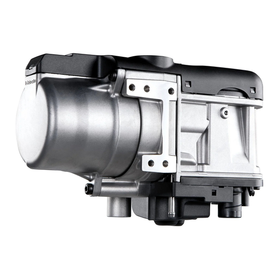
Thermo Top Evo Parking Heater
Installation Documentation
Citroen Berlingo
Validity
Manufacturer
Citroen
Motorisation
Fuel
1.6
Diesel (HDI 90)
1.6
Diesel (eHDI 90)
SG = Manual transmission
EGS 6 = Electronically controlled 6-gear transmission
from Model Year 2012
Left-hand drive vehicle
verified equipment vari-
ants:
not verified:
Total installation time:
Ident. No.: 1318865A_EN
00 0258
Model
Berlingo
Transmis-
sion type
5-gear manual
transmission
EGS 6
Manual / automatic air-conditioning system
Front fog light
Passenger compartment monitoring
Headlight washer system
approx. 8 hours
Status: 31.10.2012
E
1
Type
EG-BE No./ABE
7
e2 * 2001 / 116 * 0366 * ...
Output in kW
Displacement in
cm³
68
1560
68
1560
Engine code
9HP
9HP
© Webasto Thermo & Comfort SE
Advertisement
Table of Contents

Related Manuals for Webasto thermo top evo


Summary of Contents for Webasto thermo top evo
-
Page 1: Validity
Water Heater Thermo Top Evo Parking Heater 00 0258 Installation Documentation Citroen Berlingo Validity Manufacturer Model Type EG-BE No./ABE Citroen Berlingo e2 * 2001 / 116 * 0366 * ... Motorisation Fuel Transmis- Output in kW Displacement in Engine code sion type cm³... -
Page 2: Table Of Contents
Digital Timer Remote Option (Telestart) Necessary Components • Basic delivery scope Thermo Top Evo in accordance with price list • Installation kit for Citroen Berlingo 2012 Diesel: 1318864A • To be ordered additionally in case of automatic air-conditioning: Additional kit AAC Citroen Berlingo 1.6 eHDI: 1318866A •... -
Page 3: Information On Operating And Installation Instructions
Installation and repair may ONLY be carried out by persons trained and VEHICLE INSTALLATION REQUIREMENTS certified in a Webasto training course. NEVER try to install or repair We- 2.1. Scope basto heating or cooling systems if you have not completed a Webasto training course, you do not have the necessary technical skills and you 2.1.1. -
Page 4: Information On Validity
• Crimping pliers for cable lug / tab connector 0.5 - 6mm² • Torque wrench for 2.0 - 10 Nm • Hose clamping pliers • Metric thread-setter kit • Webasto Thermo Test Diagnosis with current software Dimensions • All dimensions in mm Tightening torque values •... -
Page 5: Preliminary Work
• Remove years that do not apply from the type and duplicate label. • Attach the duplicate label (type label) in the appropriate place in the engine compartment. Heater Installation Location 1 Heater Installation location Ident. No.: 1318865A_EN Status: 31.10.2012 © Webasto Thermo & Comfort SE... -
Page 6: Preparing Electrical System
1 Fuse holder of passenger compartment Red (rt) 4² wire of K1/87a Black (sw) 4² wire of K1/30 Green/white (gn/ws) wire of K1/86 Preparing fuse holder of passen- ger com- partment Ident. No.: 1318865A_EN Status: 31.10.2012 © Webasto Thermo & Comfort SE... - Page 7 Complete connector of metering pump after routing. Pin assignment is not relevant. 1 Connector housing Disman- 2 Lock tling con- 3 Blue/brown (bl/br) wires nector 4 Coding 5 Timer lock Ident. No.: 1318865A_EN Status: 31.10.2012 © Webasto Thermo & Comfort SE...
-
Page 8: Electrical System
1 5.5 mm dia. hole; M5x16 bolt, washer [2x], 1 Cable grommet of bonnet bowden cable retaining plate of fuse holder, nut 2 Wiring harnesses of heater, heater control 2 F1-2 fuses Ident. No.: 1318865A_EN Status: 31.10.2012 © Webasto Thermo & Comfort SE... -
Page 9: Fan Controller For Manual Air-Conditioning
Legend Heater control 6-pin connector blue Fan relay Fuse white Additional relay brown 20A fuse 30A fuse 1A fuse 25 A fuse Cutting point Wiring colours may vary. Ident. No.: 1318865A_EN Status: 31.10.2012 © Webasto Thermo & Comfort SE... -
Page 10: Heater
Produce connections as shown in wir- ing diagram. 1 Blue (bl) wire of fan switch 3 Blue (bl) wire of 5-pin connector, Pin 1 Connect- Blue (bl) wire of K2/87a ing resis- tor group Ident. No.: 1318865A_EN Status: 31.10.2012 © Webasto Thermo & Comfort SE... - Page 11 1 Green/yellow (gn/ge) wire of earth wire 2 Green/yellow (gn/ge) wire of 6-pin con- nector A Connect- Black (sw) wire of K2/87 ing fan Brown (br) wire of K2/30 switch Ident. No.: 1318865A_EN Status: 31.10.2012 © Webasto Thermo & Comfort SE...
-
Page 12: Fan Controller For Automatic Air-Conditioning
30A fuse grey 1A fuse 25 A fuse IPCU Pulse width modulator IPCU adjustment values: Duty cycle: 33% Frequency: 1000Hz Voltage: Cutting point Function: High-side Wiring colours may vary. Ident. No.: 1318865A_EN Status: 31.10.2012 © Webasto Thermo & Comfort SE... - Page 13 1 Socket of IPCU covered (installed behind original vehicle strut) 2 M5x16 bolt, large diameter washer, Installing flanged nut IPCU sock- 1 Original vehicle bolt Brown (br) wire of IPCU/85, cable lug IPCU earth connection Ident. No.: 1318865A_EN Status: 31.10.2012 © Webasto Thermo & Comfort SE...
- Page 14 2 Orange (or) wire of connector B, Pin 2 Connec- 3 Orange (or) wire of GR tion to fan Red (rt) wire of K1/87a module Black (sw) wire of K1/30 Yellow (ge) wire of IPCU/15 Ident. No.: 1318865A_EN Status: 31.10.2012 © Webasto Thermo & Comfort SE...
-
Page 15: Digital Timer
Fasten receiver 1 with double-sided adhesive tape. Installing receiver 1 Antenna Installing antenna Temperature sensor for HTM100 only 1 Fasten temperature sensor with adhe- sive tape Installing tempera- ture sensor Ident. No.: 1318865A_EN Status: 31.10.2012 © Webasto Thermo & Comfort SE... -
Page 16: Preparing Installation Location
1 M6x20 bolt, existing threaded hole 2 Copy hole pattern 3 Mount retaining plate with bracket loosely Copying hole pat- tern 1 Copy hole pattern [2x] Copying hole pat- tern Ident. No.: 1318865A_EN Status: 31.10.2012 © Webasto Thermo & Comfort SE... - Page 17 1 Bracket of air intake pipe 3 12 mm dia. hole Preparing bracket of air intake pipe 1 Retaining plate with bracket 2 M6x20 bolt, flanged nut Installing bracket Ident. No.: 1318865A_EN Status: 31.10.2012 © Webasto Thermo & Comfort SE...
-
Page 18: Preparing Heater
2 5x15 self-tapping bolt, retaining plate of water connection pieces Installing water con- nection pieces Tap threads with 5x13 self-tapping screws 1 [4x] and install loosely (turn max. 3 threads). Premount- ing bolts loosely Ident. No.: 1318865A_EN Status: 31.10.2012 © Webasto Thermo & Comfort SE... - Page 19 3 90° 18x18 connecting pipe, 25 mm dia. spring clip Premount- ing hoses Discard section X . 1 Combustion air pipe a = 260 Cutting combus- tion air pipe to length Ident. No.: 1318865A_EN Status: 31.10.2012 © Webasto Thermo & Comfort SE...
- Page 20 2 90° moulded hose, 10 mm dia. clamp [2x] 3 Fuel line Premount- ing heater Images show vehicle with EGS 6. 1 Tighten 5x13 self-tapping bolt [2x] Installing heater 1 Tighten 5x13 self-tapping bolt [2x] Installing heater Ident. No.: 1318865A_EN Status: 31.10.2012 © Webasto Thermo & Comfort SE...
-
Page 21: Combustion Air
Citroen Berlingo Combustion Air 1 Combustion air pipe 2 Cable tie [2x each] 3 Silencer 4 ABS bracket Installing silencer Ident. No.: 1318865A_EN Status: 31.10.2012 © Webasto Thermo & Comfort SE... -
Page 22: Fuel
8mm dia. hole at position 3 in original vehicle sealing 2 . 1 Original vehicle line duct 4 Fuel line, metering pump wiring harness Installing lines Ident. No.: 1318865A_EN Status: 31.10.2012 © Webasto Thermo & Comfort SE... - Page 23 1 Wiring harness of metering pump, con- nector mounted 2 Fuel line of heater 3 Hose section, 10 mm dia. clamp [2x] Connect- ing meter- ing pump Ident. No.: 1318865A_EN Status: 31.10.2012 © Webasto Thermo & Comfort SE...
- Page 24 Check that they have freedom of movement. 1 180° moulded hose, 10 mm dia. clamp [2x] 2 Fuel line of fuel standpipe Connect- ing meter- ing pump Ident. No.: 1318865A_EN Status: 31.10.2012 © Webasto Thermo & Comfort SE...
-
Page 25: Coolant Circuit
The connection should be "inline" based on the following diagram: Hose rout- ing dia- gram All spring clips = 25 mm dia. 1 = Black (sw) rubber isolator All connecting pipes = 18x18 mm dia. Ident. No.: 1318865A_EN Status: 31.10.2012 © Webasto Thermo & Comfort SE... - Page 26 3 Circulating pump mounting Mounting circulating pump 1 Wiring harness of circulating pump 2 Wiring harness of heater [2x] 3 Cable tie Mounting wiring har- nesses Connect- ing heater outlet Ident. No.: 1318865A_EN Status: 31.10.2012 © Webasto Thermo & Comfort SE...
- Page 27 1 Slide on black (sw) rubber isolator and align 2 Cable tie [2x] Routing in engine compart- ment 1 Hose on heat exchanger inlet Connect- ing heat ex- changer inlet Ident. No.: 1318865A_EN Status: 31.10.2012 © Webasto Thermo & Comfort SE...
- Page 28 1 Slide on black (sw) rubber isolator and align Connect- ing circu- lating pump Align hoses. Ensure sufficient distance from neighbouring components. 1 Hose bracket Mounting hose bracket Ident. No.: 1318865A_EN Status: 31.10.2012 © Webasto Thermo & Comfort SE...
-
Page 29: Exhaust Gas
20° 1 Perforated bracket Angling down per- forated bracket of silencer 90° 100° 1 7 mm dia. hole [2x] Holes in cross member Ident. No.: 1318865A_EN Status: 31.10.2012 © Webasto Thermo & Comfort SE... - Page 30 Ensure sufficient distance to neighbouring components; correct if necessary. 1 Exhaust end section 2 M6x20 bolt, p-clamp, flanged nut 3 Perforated bracket Mounting 4 M6x20 bolt, flanged nut end section 5 Hose clamp Ident. No.: 1318865A_EN Status: 31.10.2012 © Webasto Thermo & Comfort SE...
-
Page 31: Final Work
Align exhaust end section 2 centrally in the recess of underride protection 1. Aligning end section Webasto Thermo & Comfort SE Postfach 1410 82199 Gilching Germany Internet: www.webasto.com Technical Extranet: http://dealers.webasto.com Ident. No.: 1318865A_EN Status: 31.10.2012 © Webasto Thermo & Comfort SE... -
Page 32: Operating Instructions For Manual Air-Conditioning
Citroen Berlingo Operating Instructions for Manual Air-Conditioning Please remove this page in case of manual air-conditioning and add it to the vehicle operating instructions. Note: We recommend matching the heating time to the driving time. Heating time = driving time Example: For a driving time of approx. -
Page 33: Operating Instructions Automatic Air-Conditioning
Citroen Berlingo Operating Instructions Automatic Air-Conditioning Please remove this page in case of automatic air-conditioning and add it to the vehicle operating instructions. Note: We recommend matching the heating time to the driving time. Heating time = driving time Example: For a driving time of approx.
Need help?
Do you have a question about the thermo top evo and is the answer not in the manual?
Questions and answers