Webasto Thermo Top Evo Manual
- Installation documentation (64 pages) ,
- Manual (57 pages) ,
- Workshop manual (52 pages)
Advertisement
Introduction

Improper installation or repair of Webasto heating and cooling systems can cause fire or the leakage of deadly carbon monoxide leading to serious injury or death.
To install and repair Webasto heating and cooling systems you need to have completed a Webasto training course and have the appropriate technical documentation, special tools and special equipment.
Only genuine Webasto parts may be used. See also Webasto air and water heaters accessories catalogue.
NEVER try to install or repair Webasto heating or cooling systems if you have not completed a Webasto training course, you do not have the necessary technical skills and you do not have the technical documentation, tools and equipment available to ensure that you can complete the installation and repair work properly.
ALWAYS carefully follow Webasto installation and repair instructions and heed all WARNINGS.
Webasto rejects any liability for problems and damage caused by the system being installed by untrained personnel.
Contents and purpose
This workshop manual is used to support trained personnel which repairs the petrol and diesel models of the Thermo Top Evo parking heater water heaters and auxiliary heaters.
Meaning of signal words
Throughout this manual, the signal words WARNING, IMPORTANT and NOTE have the following meanings:

This heading is used to highlight operating instructions or procedures which, if not or not correctly followed, may result in personal injury or fatal accidents.

This heading is used to highlight operating instructions or procedures which, if not or not correctly followed, may result in damage to the equipment or its components.
 NOTE
NOTE
This heading is used to direct your attention to a special feature deemed essential to highlight.
Additional documentation to be used
This workshop manual contains all necessary information and instructions for the repair of Thermo Top Evo water heaters.
Information of the general installation and operating instructions is not contained in this workshop manual. If repairs are necessary, these documents must also be used.
Safety precautions and regulations
In principle, the general accident prevention regulations and current works safety instructions are applicable.
"General safety precautions" which go beyond the scope of these regulations are listed in the following.
Any special safety regulations relevant to this instruction manual will be highlighted in the relevant sections or text passages of the procedures.
Statutory regulations governing installation
Type approvals according to ECE-R 10 (EMC) and ECER 122 (Heater) exist for the Thermo Top Evo heater.
For the installation, primarily the regulations of the directive ECE-R 122 and the regulations contained in the installation instructions must be observed.
NOTE
The regulations of these guidelines are binding in the scope of the EU Directive 70/156/EEC and/or EC/2007/46 (for new vehicle models from 29/04/2009) and should also be observed in countries in which there are no special regulations!
The Thermo Top Evo water heaters were designed for installation in Class M1 motor vehicles. The installation in motor vehicles of the classes O, N2, N3 and hazardous substance transports according to the EC Directive EEC/70/156 and/or Basic Directive EC/2007/46 is not permissible. The applicable regulations must be taken into account when installing in special vehicles. Other uses are possible in consultation with Webasto.
General safety precautions
The repair and commissioning of the unit may only be carried out by personnel trained by Webasto. The repair and installation of the unit may only be carried by trained experts in accordance with the workshop manual and the installation instructions.
The year of initial start-up must be permanently marked on the type label by removing the inapplicable years.
The heater must not be operated:
- In filling stations and tank farms.
- At locations at which highly flammable gases or dusts can form, and at locations at which highly flammable liquids or solid materials are stored (e.g. near fuel, coal and wood dust, grain warehouses, dry grass and leaves, cardboard, paper, etc.)
- In enclosed rooms (e.g. garages), not even via the timer or Telestart.
- Without at least 20% brand name anti-freeze in the water of the heating circuit.
There is a danger of burns, as the heater and the attached parts may be extremely hot.
The heater:
- may not be subjected to temperatures of more than 120°C (storage temperature). otherwise the electronics may suffer permanent damage.
- may only be operated with the fuel and the nominal voltage specified on the type label.
- must be shut down by immediately switching off the heater and removing the fuse in case of heavy smoke, unusual combustion noises or fuel odours. The heater must not be restarted until the unit has been checked exclusively by personnel duly trained by Webasto.
- must be switched off during work in the engine compartment and may not be cleaned with highpressure cleaning units or compressed air.
- Must be put into operation at least once a year for 10 minutes with the engine cold and the lowest fan speed selected.
- Must be checked by a professional every 2 years, at the commencement of the heating period.
Liability:
- Non-compliance with the operating instructions and the warnings contained therein will lead to the exclusion of all liability by Webasto.
The same also applies if repairs are not undertaken by professionals or without using genuine spare parts. This invalidates the type approval for the heater and its homologation/ECE type permit.
Be sure to read the operating instructions of the heater before commissioning.
Spare parts
The ID numbers of available spare parts can be found in the Webasto spare parts catalogue or online at http://dealers.webasto.com.
NOTE
Before ordering the spare part, please make sure that the parking heater has been equipped as a parking-auxiliary heater (e.g. by reading out the EOL data record with Webasto Thermo Test PC Diagnosis).
General description
The Thermo Top Evo water heater is used to compensate the heat deficit which results with consumption-optimised vehicle engines.
The Thermo Top Evo parking heater is used:
- to heat the passenger compartment,
- to defrost the vehicle windows,
- to preheat water-cooled vehicle engines.
The Thermo Top Evo auxiliary heater can be upgraded to a parking-auxiliary heater with an additional kit.
As the external appearance is identical, the heaters are marked with "Petrol" or "Diesel on the type label; there is no special marking for the auxiliary heater. The heaters may only be operated with the predetermined fuel and only with the respectively specified type of electrical connection.
NOTE
This workshop manual describes the retrofit variant of the heater. For heaters installed directly at the vehicle manufacturer's plant, other control units with other connectors and other software and other application parts may be used which are not described in this manual. Information is only available for these heaters via the documentation of the vehicle manufacturer.
The heater designed according to the evaporator principle operates in the full-load and partial-load mode, controlled by the temperature sensor.
The heater consists of the combustion-air fan unit (G) with the control unit, the heat exchanger (W) with the water connection piece and the burner.

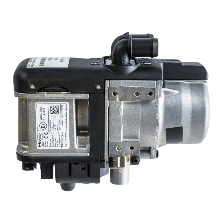
Fig. 201 Thermo Top Evo
Combustion-air fan unit/control unit
The combustion-air fan unit contains:
- the heater type label
- the connection piece for the combustion air pipe
- the control unit with the plug-in contacts
- the engine and the impeller
The combustion air fan supplies the air required for the combustion process from the combustion air inlet to the combustion chamber.
NOTE
It is not permissible to dismantle the combustion-air fan unit.

Fig. 202 Combustion-air fan unit
Burner unit
The fuel-air mixture is processed and the actual combustion takes place in the burner unit. The fuel flows via the fuel pipe to the evaporator, is distributed there and is evaporated using the glow plug. The air required for combustion is provided by the combustion-air fan unit and flows into the combustion chamber via holes in the burner.

Fig. 203 Burner unit
B1 = Combustion pipe with evaporator mount and evaporator
B2 = Retaining spring for glow plug
B3 = Cooling flag for glow plug
B4 = Glow plug/Flame monitor
B5 = Fuel pipe
B9 = Connector for glow plug/ flame monitor
Glow plug/Flame monitor
The glow plug/flame monitor is connected to the control unit (SG) via an electrical line with a connector (B9). The glow plug is fastened to the evaporator mount with a retaining spring (B2). A cooling flag (B3) provides for heat dissipation from the glow plug, and therefore reduces the temperature at the glow-plug connection lines.
The glow plug ignites the fuel-air mixture in the start-up phase and is switched off after the "full load" state is reached. From this point it is used exclusively for flame monitoring. If the flame extinguishes, the electrical resistance in the glow plug drops as the result of the missing heat application. This is detected in the control unit.
Heat exchanger
The heat generated in the heat exchanger by combustion is transferred to the coolant circuit.

Fig. 204 Heat exchanger
W1 = Heat exchanger
W2 = Cable of temperature sensors
W3 = Ejomat DG 40x10 self-tapping screw
W4 = Retaining spring for sensors
W5 = Temperature sensor
W6 = Overheating sensor
Temperature sensor and overheating sensor
The temperature sensor detects the coolant temperature in the heat exchanger of the heater as an electrical resistance. This signal is fed to the control unit, where it is processed.
The temperature sensor (W5) and the overheating sensor (W6) for a unit together with the cable and the connector.
The overheating sensor protects the heater against impermissibly high operating temperatures. This reacts at a temperature above 125°C and switches off the heater.
Circulation pump
The U4847 Econ circulation pump ensures a feed rate of the coolant in the vehicle heater and heater circuit. The pump is switched on with the control unit and runs during the entire operation of the heater. The circulation pump is a centrifugal pump with a brushless EC motor.
The circulation pump is equipped with a 2-pin connector output and is connected to the control unit (SG) by means of a separate wiring harness. The circulation pump must not be used after being dropped.

Fig. 205 U4847 Econ circulation pump
Metering pump
The fuel metering pump is a combined pumping, metering and shut-off system. This dry-primeable reciprocating piston pump pumps the fuel from the vehicle fuel tank to the fuel connection piece of the heater via fuel lines. Installation is usually carried out near the fuel tank. The metering pump contains no pulsation damper and is equally well-suited for diesel and petrol. The metering pump is connected to the control unit via the heater-unit wiring harness and to an earthing point on the vehicle body.
Only the model DP42 fuel metering pump may be used for the Thermo Top Evo heater. Observe the model designation on the component for this purpose. When replacing the metering pump, the CO2 settings must be checked.

Fig. 206 DP42 metering pump
Heater controls
NOTE
Additional information on the respective heater control is contained in the specific installation and operating instructions.


Description of operation

Fig. 301 Functional illustration of Thermo Top Evo heater
Switching on/starting process
The heater is started with the parking heater via a switch-on signal of the heater control. And with the auxiliary heater when the auxiliary heating signal is present at the heater unit inlet. The auxiliary heating signal is dependent on previously defined switch-on conditions, such as the outside temperature (below 5°C) and engine running.
NOTE
The Thermo Top Evo heaters described in this manual can only be put into operation with a W-bus-capable heater control, or with the Webasto Thermo Test PC Diagnosis. With the Webasto Thermo Test PC Diagnosis connected, the connection to other heater controls is disconnected. Different configuration options are shown in the system wiring diagram.
When the heater is started up, the combustion air fan, the circulation pump and the glow plug are put into operation. Then the metering pump is connected. The petrol heater starts up at the highest load level. In contrast, the diesel heater starts up at a low load level and is slowly adjusted upward to full load in the form of a ramp.
During this start-up phase, it is checked whether a flame has formed with the glow plug.
If no flame is detected or the flame extinguishes, then automatic restarting can be initiated. If no flame is formed once again, the starting attempt is ended. Then a fault lock-out is carried out with run-on of the combustion air fan. The heater cannot be restarted until after switch-off. Depending on the coolant temperature, the control unit decides which starting process is selected. Start-up processes are identical with regard to the sequence, however differ in the length of the individual phases (preheating, fuel delivery, etc.).
Heating mode
After full load is reached, the glow plug assumes the function of the flame monitor and checks the flame. The heater switches into the energy-saving partial-load mode after a certain temperature (around 80°C) is reached. If the temperature continues to increase, the heater switches into the control break from a pre determined temperature (approx. 84°C).
After the coolant has cooled down, the heater restarts in the partial-load mode. If the temperature rises to a defined switching temperature again, the heater switches into the control break again. If the temperature of the coolant continues to drop due to an increased heat requirement during partial load operation, then the heater switches over to full load operation again.
The temperature of the switching points is programmed in the control unit.
If a flame out occurs during normal combustion operation, a restart is automatically initiated.
Restarting after fault lock-out
After the fault cause has been eliminated, the heater must be switched on again with the normal switch-on signals. This does not apply after overheating or if a fault occurs several times without intermediate combustion operation.
Starting after long period of non-use
Longer periods of non-use have no effect on the starting function of the heater. However, limitations must be made here with regard to filling of the fuel lines. Especially with petrol heaters, the fuel evaporates from the fuel line in the summer months. As a result, it must be expected that several complete starting attempts will be required for initial starting. Commissioning must them be carried out with the Webasto Thermo Test PC Diagnosis.
Prime the heater with fuel using the Webasto Thermo Test PC Diagnosis:
Press the fill line button and fill the lines until fuel is present at the heater.
Switching off/Switch-off function
When a switch-off signal is received, when the burn-out temperature is reached, when the set heating time is reached or if faults occur, combustion operation is ended and a burn-out is initiated. In the process, the control of the fuel metering pump is immediately interrupted and the fan speed is decreased. After the burn-out is complete the fan speed is increased to cool the combustion chamber.
NOTE
The run-on time and the combustion-air fan speed are dependent on the heater model and operating mode from which the heater is switched off.
Switch-off or new switch-on signals are processed according to the following rules:
- A switch-off signal on a heater control always as priority irrespective of the heater operating state.
- If the original switch-on signal is no longer active, or if the included heating duration has expired, then this is interpreted as a switch-off signal.
- New switch-on signals are ignored until the original switch-on signal is no longer active.
- It is therefore not possible to change the heating time during operation. The heater must be switched off and then on again with the changed heating duration.
- If the heater has been started as an auxiliary heater, then switching off the vehicle engine must be interpreted as a switch-off signal (legal requirement).
- A restart of the heater is not possible until after the burnout has completed and the first cooling phase (forced run-on) has been ended. New switch-on signals are temporarily stored and are not followed until then.
Technical Data
The technical data is contained in the installation instructions.
Troubleshooting
Faults
Fault lock-out and heater lock-out
Faults which occur are assigned to various categories:
Fault
- A fault which occurs has no effect on the current combustion operation; an fault message is stored.
- A fault which occurs causes automatic restarting or a restart; a fault message is stored.
Fault lock-out
- A fault which occurs in the power supply or in the control unit results in an immediate heater switch-off without burn-out. No fault is entered.
- A fault which occurs results in a heater switch-off (burnout) or prevents heater start-up; a fault message is stored. Restarting requires a switch-off signal and a repeat switch-on signal.
Permanent heater lock-out due to multiple repetitions of an fault
- If a fault from 4) occurs 6 times consecutively without the full load state being reached, then the heater is locked out and a fault message is stored. The lock-out can only be cancelled at the workshop. If the fault is an undervoltage switch-off due to a weak battery, then no lock-out occurs.
Overheating lock-out (heater is overheated)
- The heater overheats and is locked out; a fault message is stored.
The lock-out can only be cancelled at the workshop.
NOTE
If a fault lock-out and a subsequent heater lock-out occurs, then no display occurs on the heater controls. A start-up of the heater is permitted; a fault is no longer present. In case of a heater lock-out, the heater is locked out and cannot be switched on.
Fault lock-out due to undervoltage or overvoltage
In case of an undervoltage of 11.5 V for a certain period (20 sec.), a fault lock-out with a run-on occurs. The specified undervoltage is software-dependent and is measured at the control unit input.
In case of an overvoltage of 16.0 V (measured on the heater) for a certain period (5 sec.), a fault lock-out with run-on also occurs.
Fault release
After the fault cause is eliminated, the fault release is carried out by switching the heater off and then on again.
A permanent heater lock-out/overheating lock-out can only be cancelled with the Webasto Thermo Test PC Diagnosis. The heater faults stored in the fault memory must be read out and printed with the Webasto Thermo Test PC Diagnosis. To delete the heater lock-out without clearing the fault memory, select the menu command Fault memory/Delete heater lock-out.
In exceptional cases, the heater lock-out can be cancelled by disconnecting the power supply of the control unit (e.g. by removing the fuse F1, 20 A for at least 10 seconds). The fault must be eliminated beforehand. (See Troubleshooting Section). The fuse must be pulled within 10 sec. after switching on the heater.
General fault symptoms
The following chapter contains a general overview of the fault symptoms with the heater installed.
Troubleshooting work demands precise knowledge of the structure and theory of operation of the various components and must be carried out by trained personnel only.
Troubleshooting
Possible fault during heater operation are sorted in this chapter according to the following criteria:
- Component faults entered in the fault memory. A specific component which is defective is contained in the control-unit fault memory. The component or nexthighest assembly must be replaced.
- General faults entered in the fault memory . The heater has detected a problem (e.g. no starting), however cannot identify the specific cause. Troubleshooting is structured so that the periphery of the heater is checked (e.g. the fuel supply) before the heater or a sub-component is replaced.
- Fault without fault entry in the control unit. Troubleshooting is structured so that the periphery of the heater is checked (e.g. the fuel supply) before the heater or a sub-component is replaced.
Reading out fault memory
The fault memory of the heater can be read out with the Webasto Thermo Test PC Diagnosis.
The fault memory displays up to 8 different faults. The older an fault is, the higher its number. The current operating duration and the current start-up number are entered in the control unit summary.
If a fault is entered as "current" then the control unit has discovered this fault since the last switch-on. The fault message "Initial starting attempt failed" remains current until either full-load combustion operation is achieved in the restart or the second start-up also fails. In this case, the fault message "Initial starting attempt failed" is deleted and replaced with "No start".
The fault message "Flame abort" remains current until the heater is switched off or several flame aborts lead to the heating mode being aborted. In this case, the fault message "Flame abort" is deleted and replaced with "Flame failure".
NOTE
The operation of the diagnostic unit is explained in the operating instructions. W bus must be entered under Heater model.
It is recommended that the operating and fault data and the extended fault environment conditions be printed out.
Component fault entered in the fault memory
| Fault code (HEX) | Fault code (DEZ) | WTT* fault message | Fault details with doubleclick in WTT* | Recommended workshop action |
| 00 | - | No error | No error | No activity required |
| 01 | 1 | Defective control unit | Defective control unit, off-line programming is not performed\or water temperature sensor defective | Delete fault, carry out fault release/heater lock-out on heater, restart heater |
| 08 | 8 | Metering pump short circuit | Metering pump has short circuit to ground | Conduct electrical test of fuel system |
| 0B | 11 | Circulation pump short circuit | The connected line of the water pump has a short circuit to earth\nor the engine is overloaded | Conduct electrical test of coolant system |
| 10 | 16 | Coolant changeover valve short circuit | The coolant changeover valve has a short circuit to earth | Conduct electrical test of coolant changeover valve |
| 13 | 19 | Vehicle fan power circuit short circuit | The vehicle fan power circuit has a short circuit to earth | Conduct troubleshooting in area of vehicle fan (see Faults without fault entry in control unit Section, Fig. 504, Point 13) |
| 15 | 21 | Combustion air fan blocked | Combustion air fan is blocked |
|
| 19 | 25 | Glow/ignition element power circuit short circuit | Glow plug / electronic ignition unit has short circuit to ground | Conduct electrical test of glow plug |
| 1B | 27 | Overheat sensor short circuit | The connected line of the element has a short circuit to earth | Conduct electrical test of temperature sensors |
| 2D | 45 | The combustion-air fan power circuit is defective | Fan motor speed is below value to be expected | Delete fault, carry out fault release/heater lock-out on heater, restart heater |
| 2E | 46 | The glow/ignition-element power circuit is defective | Glow plug resistance is outside the value range | In case of multiple occurrences (> 3):
|
Fig. 501 Overview of component faults entered in the fault memory
| Fault code (HEX) | Fault code (DEZ) | WTT* fault message | Fault details with doubleclick in WTT* | Recommended workshop action |
| 3A | 58 | W-bus/LIN-bus short circuit to earth | No additional information available | Troubleshooting in area of W bus communication |
| 3C | 60 | Internal control unit fault 60 | No additional information available | Delete fault, carry out fault release/heater lock-out on heater, restart heater |
| 3D | 61 | Internal control unit error 61 | No additional information available | Delete fault, carry out fault release/heater lock-out on heater, restart heater |
| 3E | 62 | Internal control unit error 62 | No additional information available | Delete fault, carry out fault release/heater lock-out on heater, restart heater |
| 3F | 63 | Wrong version dataset loaded | No additional information available | Delete fault, carry out fault release/heater lock-out on heater, restart heater |
| 40 | 64 | Glow plug / electronic ignition unit - glow filament interruption | One of the heating circuits of the glow plug/electronic ignition unit is open |
|
| 81 | 129 | EOL checksum error | Checksum of EOL dataset is wrong | Delete fault, carry out fault release/heater lock-out on heater, restart heater |
| 88 | 136 | Metering pump interruption | Metering pump interrupted or short circuit to supply voltage +Ub | Conduct electrical test of fuel system |
| 89 | 137 | Combustion air fan interruption | Combustion air fan interrupted or short circuit to supply voltage +Ub | Troubleshooting in combustion air fan |
| 8B | 139 | Circulation pump interruption | Circulation pump interrupted or short circuit to supply voltage +Ub | Conduct electrical test of coolant system |
| 90 | 144 | Coolant changeover valve open circuit | The coolant changeover valve power circuit is open\nor has a short circuit to +Ub | Conduct electrical test of coolant changeover valve |
| 94 | 148 | Temperature sensor interruption | Temperature sensor interrupted or short circuit to supply voltage +Ub | Conduct electrical test of temperature sensors |
| 99 | 153 | Glow plug / electronic ignition unit interruption | Glow plug / electronic ignition unit interrupted or short circuit to supply voltage +Ub | Conduct electrical test of glow plug |
| AB | 171 | Overheat sensor interruption | Overheat sensor interrupted or short circuit to supply voltage +Ub | Conduct electrical test of temperature sensors |
Fig. 501 Overview of component faults entered in the fault memory
* WTT = Webasto Thermo Test PC Diagnosis
General faults entered in fault memory
| Fault code (HEX) | Fault code (DEZ) | WTT* fault message | Fault details with doubleclick in WTT* | Recommended workshop action |
| 00 | No error | No error | No activity required | |
| 02 | 2 | No start | After start-up has been repeated, combustion still fails to occur |
|
| 04 | 4 | Supply voltage too high | Supply voltage was too long above maximum threshold value | Conduct check of vehicle electrical-system supply voltage |
| 05 | 5 | Flame was detected prior to combustion | Flame detector signals flame before combustion operation |
|
| 06 | 6 | Heating unit overheated | Overheat protection was released |
|
Fig. 502 Overview of general faults entered in fault memory
| Fault code (HEX) | Fault code (DEZ) | WTT* fault message | Fault details with doubleclick in WTT* | Recommended workshop action |
| 11 | 17 | ECU wrong coded | Incorrect parameter block or wrong heater (diesel/gasoline) used | This fault can only occur on vehicles with CAN bus or LIN bus connection to heater:
|
| 12 | 18 | W bus communication failure | Bus fault, protocol error | Operation continues unchanged if this fault occurs. In case of frequent occurrence (> 10) and faults in heater operation:
|
| 2F | 47 | Flame abort | The flame has extinguished during operation. Another starting attempt will be carried out. | In case of frequent occurrence (> 10):
|
| 37 | 55 | Coolant temperature during initial start-up too high | No additional information available | This fault can only occur during initial start up of the heater (at vehicle manufacturer's plant):
|
Fig. 502 Overview of general faults entered in fault memory
| Fault code (HEX) | Fault code (DEZ) | WTT* fault message | Fault details with doubleclick in WTT* | Recommended workshop action |
| 38 | 56 | Initial starting attempt failed | No additional information available | In case of frequent occurrence (> 10):
|
| 39 | 57 | Initial starting attempt failed – not restarting | No additional information available | In case of frequent occurrence (> 3):
|
| 3F | 63 | Wrong version dataset loaded | No additional information available | Delete fault, carry out fault release/heater lock-out on heater, restart heater |
| 4C | 76 | Overvoltage component protection | Switching off at extremely high overvoltage for component protection | Conduct check of vehicle electrical-system supply voltage |
Fig. 502 Overview of general faults entered in fault memory
| Fault code (HEX) | Fault code (DEZ) | WTT* fault message | Fault details with doubleclick in WTT* | Recommended workshop action |
| 4E | 78 | Customer specific fault 3 | No additional information available | In case of frequent occurrence (> 3):
|
| 81 | 129 | EOL checksum error | Checksum of EOL dataset is wrong | Delete fault, carry out fault release/heater lock-out on heater, restart heater |
| 82 | 130 | No start during testrun | No start during testrun | This fault can only occur during initial start up of the heater (at vehicle manufacturer's plant):
|
Fig. 502 Overview of general faults entered in fault memory
| Fault code (HEX) | Fault code (DEZ) | WTT* fault message | Fault details with doubleclick in WTT* | Recommended workshop action |
| 83 | 131 | Flame failure | Flame interruption during combustion operation, more than FAZ (EEPROM) times | In case of frequent occurrence (> 3):
|
| 84 | 132 | Operating voltage too low | Supply voltage was too long below maximum threshold value |
|
| 86 | 134 | Excessive water temperature without combustion process | Fault will be set if water temperature has exceeded 145°C in control break | In case of multiple occurrences (> 3):
|
| 87 | 135 | Heater lock-out permanent | Permanent heater lock-out has been activated |
|
| 92 | 146 | Command refresh failure | Command refresh failure. In case of this fault no operation | Troubleshooting in area of W bus communication |
Fig. 502 Overview of general faults entered in fault memory
| Fault code (HEX) | Fault code (DEZ) | WTT* fault message | Fault details with doubleclick in WTT* | Recommended workshop action |
| 9C | 156 | Heating time exceeded | Calculated heating time from intelligent undervoltage detection exceeded |
|
| A9 | 169 | Insufficient coolant flow | The fault occurs if the coolant temperature exceeds the switching threshold for burning out during the phases Start/GPR (glow plug ramp)/FMM (flame monitor measuring phase) during the control break |
|
| AA | 170 | S on W-Bus not succeed | S on W-Bus not succeed (nor or faulty response, even after repeating telegram four times) | Troubleshooting in area of W bus communication |
| AB | 171 | Overheat sensor interruption | Overheat sensor interrupted or short circuit to supply voltage +Ub | Conduct electrical test of temperature sensors |
Fig. 502 Overview of general faults entered in fault memory
* WTT = Webasto Thermo Test PC Diagnosis
Faults without fault entry in control unit
NOTE
Before each repair on the heater, the fault memory must be read out with the Webasto Thermo Test PC Diagnosis. Existing faults must be printed before deleting and made available to the Webasto Hotline or the Warranty Department.
At low temperatures and with no wind, a minor amount of smoke and/or a slight odour may be noticeable during starting and/or burn-out.
The occurrence of fog with an exhaust system not warmed through or in case of unfavourable weather conditions is normal and cannot be avoided.
Smoke: exits directly from the exhaust end section.
Fog: becomes visible just a few centimetres after the exhaust tailpipe.
Possible faults
| Fault Description | Possible fault point (see Table Fig. 504) |
| Heater does not react | 1, 2, 3, 4, 14 |
| Heater does not heat | 5, 6, 7, 8, 10, 12 |
| Heater switches off prematurely | 1, 5, 7, 10, 12 |
| Heater has intermittent combustion | 5, 8, 10, 12 |
| Heater smokes in start-up phase | 5, 8, 10, 12 |
| Telestart cannot be tuned | 1, 3, 4, 14 |
| Heater running, vehicle passenger compartment cold | 7, 9, 11, 13, 16 |
| Heater smokes in heating phase/ white smoke | 5, 7, 8, 10, 12 |
| Heater smokes in run-on phase | 5, 10, 12 |
| Fuel odour | 5, 6, 7, 8, 10, 12 |
| Exhaust odour in passenger compartment | 5, 6, 7, 8, 10, 12 |
| Coolant loss | 9, 11 |
The overview only shows some of the possible faults. The Webasto Service Hotline must be contacted in individual cases.
Fig. 503 Overview of possible faults
Functional test of heater and its components
| Fault | Component | Recommended workshop action | Parameter |
| 1 | Power supply | Measure supply voltage under load at heater unit connector X2 (also see Fig. 916) | Undervoltage switch-off < 11.5 V |
| 2 | Clock | Press flame button, display lighting must light up | LED flickers when button is pressed |
| Check the W bus signal on Pin 2 on heater unit connector X1 or diagnostic connector with an LED lamp against "+" | |||
| 3 | Receiver (Telestart T91 and T100 HTM) | Check the W bus signal on the 6-pin connector on the receiver, Pin 2, with an LED lamp against Pin 1 "+" | LED flickers when On button is pressed |
| 4 | Transmitter (Telestart) | Assign transmitter to receiver/teach in accordance with instructions | |
| Check operating mode on Telestart hand-held transmitter (heat/ventilate) | |||
| Battery of hand-held transmitter should have sufficient capacity (new) | |||
| 5 | Metering pump | Check continuity from connector X1, Pin 6 to connector X7 (blue wire) Check continuity from connector X7 (brown wire) to earth | |
| Measure coil resistance of DP42 metering pump | 5.20 ohms ± 0.5% at 20 ± 2°C | ||
| Measure feed rate with Webasto Thermo Test PC Diagnosis | Petrol feed rate: 7 Hz, 60 sec: 11.6 to 14.3 ml | ||
| Diesel feed rate: 7 Hz, 60 sec: 12.0 to 14.6 ml | |||
| Check connection of fuel line on connection piece in accordance with general installation instructions | |||
| 6 | Glow plug | Measure glow plug resistance on glow plug connector X5 (white wire). | At 25 ± 5°C: 0,235 to 0.355 ohms |
| 7 | Temperature sensors | For information on checking the cold resistance of the sensors | At 20 ± 6°C: W5 (Pin 2 and 4) 2,296 to 5,047 ohms W6 (Pin 1 and 3) 30 to 250 ohms |
| 8 | Combustion air fan | Conduct component test on function of fan motor with Webasto Thermo Test PC Diagnosis. No rubbing noises may be heard. Check CO2 settings |
Fig. 504 Overview of functional test of heater and its components
| Fault | Component | Recommended workshop action | Parameter |
| 9 | Circulation pump | Conduct component test to check function of circulation pump with Webasto Thermo Test PC Diagnosis. | Touch with hand; pump functions if slight vibration can be felt |
| Measure resistance on circulation pump connector X4 | 10 ± 1 kohms | ||
| Check pump for leaks | |||
| Check self-venting installation position, also see general installation instructions | |||
| 10 | Fuel integration | Are bubbles visible in the fuel line/are bubbles pumped during feed rate test (see Point 5)? If they are, then change connection or routing of line. Check integration in vehicle fuel system. Observe fuel level (no reserve); is fuel tank extraction correct? Inspect fuel lines for leaks, kinking or clogging. | |
| 11 | Coolant circuit | Check integration in coolant circuit of motor vehicle in accordance with general installation instructions/ vehicle-specific installation instructions | |
| Check whether coolant circuit is correctly bled | |||
| Check circulation in coolant circuit | |||
| Eliminate kinks and rubbing spots | |||
| Check leaks on heater, water connection piece, circulation pump and hoses and eliminate | |||
| Check whether coolant mixing ratio is suitable | e.g. down to -40°C | ||
| 12 | Exhaust system and intake air system | Check whether intake pipe and exhaust pipe are routed in accordance with general installation instructions/vehicle-specific installation instructions | |
| Check to make sure lines are not clogged | |||
| Eliminate existing leaks on intake pipe and exhaust pipe (no CO2 in intake air) | |||
| Check whether sufficient distance is present to passenger compartment fresh-air intake of vehicle | |||
| 13 | Vehicle fan | Check switching signal on relay K1, Pin 86 (also see wiring diagram in general installation instructions/ vehicle-specific installation instructions) | |
| Observe coolant temperature (K1 switches at approx. 50°C) | |||
| Check flap position of vehicle heater (air conditioning set to HI) | |||
| 14 | Control unit/ heater locked | Unlock in accordance with Fault release Section |
Fig. 504 Overview of functional test of heater and its components
| Fault | Component | Recommended workshop action | Parameter |
| 15 | Control unit (fault memory) | Read out fault memory with Webasto Thermo Test PC Diagnosis, then print out and clear fault memory | |
| Include printed fault log when sending heater to Webasto. | |||
| Complete replacement of fan unit if control unit is defective. | |||
| 16 | Coolant changeover valve | Check continuity from connector X1 Pin 4 to connector X15. Check continuity from connector X15 (brown wire) to earth. | |
| Apply 12 V voltage to connector X1, Pin 4 | Valve switches audibly |
Fig. 504 Overview of functional test of heater and its components
Operating tests
General
This section describes the tests of the heater and its components in the installed and the removed state.
Operating checks in vehicle
- Set the vehicle van to fan speed 1 - 2 or to the speed recommended in the vehicle-specific operating instructions.
- Make sure that the fresh-air inlet is clear of foreign bodies (snow, leaves, etc.) and any pollen and dust filters are clear.
- Make sure that the coolant circuit and the fuel system are carefully bled in accordance with the vehicle manufacturer's specifications.
- Switch on the heater with the heater control.
When the heater is switched on, the circulation pump and the combustion air fan run. This is audible. The vehicle fan is switched on by the heater when the coolant temperature has reached 30 to 50°C (vehicle-specific). After a maximum of 240 sec, exhaust can be seen exiting at the exhaust muffler or connection piece. - Allow the heater to run in the combustion mode. Check the heating effect at the outlet nozzles of the vehicle fan.
![information]() NOTE
NOTE
The heating effect is dependent on several factors: To evaluate it, the outside temperature, the vehicle model, the engine temperature, the type of integration in the vehicle cooling system, the quantity of coolant to be heated up and the time since the start must be used for the evaluation. The coolant temperature determined by the heater and the coolant or engine temperature indicated by the vehicle may differ considerably, as the respective sensors are installed at different locations and may evaluate different temperatures. - Switch off the heater again with the heater control.
A maximum run-on of 175 sec is activated when the heater is switched off. This is audible due to a reduction of the combustion noise. The continued running of the combustion air fan with an increase in the speed after approx. 60 sec is used for active cooling of the heater and operation of the circulation pump. This is followed by a complete switch-off.
Circuit diagrams
Fig. 701 shows the circuit of the Thermo Top Evo heater, parking heater and heater control.
Legend for wiring diagram.
| Cable colours | |
| bl | blue |
| br | brown |
| ge | yellow |
| gn | green |
| gr | grey |
| or | orange |
| rt | red |
| sw | black |
| vi | violet |
| ws | white |

Fig. 701 Wiring diagram of Thermo Top Evo parking heater and 12 V digital timer.
| Item | Description | Comment |
| j | Present in vehicle | Vehicle fan |
| k | Fan controller | |
| l | Air-conditioning control unit | |
| m | Aerial | |
| n | Plug connection | View of Line Side |
| o | Indicator for vehicle engine running (in-line operation of solenoid coolant valve) | Optional Must be activated with a data record |
| p | Low active auxiliary heating request | Optional Must be activated with a data record Gnd/0 V = ON open or no signal or U > 6 V = OFF |
| | Outside temperature | |
| X1 | 6-pin connector | Vehicle signal |
| X2 | 2-pin connector | Power supply |
| X3 | 4-pin connector | Temperature sensors |
| X4 | 2-pin connector | Circulation pump |
| X5 | 2-pin connector | Glow plug |
| X6 | 2-pin connector | not in use |
| X7 | 2-pin connector | Metering pump |
| X8 | 2-pin connector | Diagnosis plug |
| X9 | 2-pin connector | Diagnosis bridge |
| X10 | 4-pin connector | Heater controls |
| X11 | 4-pin connector | Heater controls |
| X12 | 4-pin connector | Temperature sensor for W bus |
| X13 | 4-pin connector | Temperature sensor for W bus |
| X14 | 6-pin connector | Telestart T91/T100 HTM |
| X15 | 2-pin connector | Solenoid coolant valve Changeover to in-line operation of solenoid coolant valve only in conjunction with 12 V signal on Pin 1 |
| X16 | 2-pin connector | Circulation pump |
| X17 | 4-pin connector | Telestart button |
| X18 | 4-pin connector | Telestart button |
| A1 | Heater | Thermo Top Evo |
| A2 | Control unit | |
| A3 | Digital timer 1533 | |
| A4 | Telestart T91 | |
| A5 | Telestart T100 HTM | |
| A6 | Fuse holder | |
| A7 | W bus temperature sensor | |
| A8 | IPCU | Fan controller |
| A9 | Relay socket with fuses | |
| A10 | Telestart button | |
| F1 | Fuse | 20 A |
| F2 | Fuse | 30 A |
| F3 | Fuse | 1 A |
| F4 | Fuse | 25 A |
| B1 | Temperature sensor | Coolant temperature sensor |
| B2 | Temperature sensor | Overheating |
| M1 | Motor | Combustion air fan |
| M2 | Motor | Circulation pump |
| M3 | Vehicle fan | |
| S1 | Vehicle fan switch | |
| S2 | Vehicle fan switch | |
| S3 | Switch ON/OFF | Optional |
| S4 | Switch for auxiliary heating request | |
| E | Glow plug | |
| Y1 | Metering pump | DP 42 |
| Y2 | Solenoid coolant valve | |
| K1 | Relay | Fan relay |
Servicing work
This section describes the servicing work that can be carried out on the heater and its components while installed.
Work on the heater
The power supply must always be disconnected at the vehicle battery before carrying out any work on the heater. The power supply must not be disconnected whilst the heater is operating or slowing down as a result of the risk of the heater overheating and the overheating protection thus being tripped. If repair work is carried out on the heater, it must be completely removed.
After the heater and all coolant-carrying components have been installed, the entire coolant system must be filled, bled and checked for leaks with the specified system pressure in accordance with the vehicle manufacturer's instructions. The general installation instructions and the vehicle-specific installation instructions for the heater must be observed when carrying out repairs which make it necessary to change the installation location.
NOTE
Any coolant running off should be collected using an appropriate container.
CO2 setting
NOTE
After repairing the heater and/or replacing the metering pump, the setting of the CO2 value should be checked.
After replacing the fan unit or the control unit, the CO2 value must be checked and reset if necessary.
The CO2 setting is carried out with Webasto Thermo Test PC Diagnosis and the CO2 testers specified by Webasto. Common AU large gas quantity emission testers cannot be used for the CO2 setting of the heater.
The heater is optimally set to a CO2 value for operation at altitudes between 0 and 1,000 m above sea level at the factory. Continuous operation above 1,000 m above sea level can lead to heavy smoking and formation of soot. To prevent a failure of the unit and danger, the CO2 value should be adjusted in consultation with Webasto.
NOTE
The CO2 measurement and setting must be carried out in the full load heater operating mode (display in Webasto Thermo Test: Full Load). The CO2 value is corrected in selection point 2.7.1. CO2 calibration of Webasto Thermo Test PC Diagnosis. The measurement of the CO2 content is carried out approx. 20 mm in front of the end of the exhaust outlet inside the exhaust pipe with a CO2 tester (e.g. from MSI).
The following table shows the nominal CO2 setting value in full-load combustion operation in dependence on the geodetic altitude at which the setting is made.
| Altitude [m above sea level] | Nominal CO2 setting value at 20°C ambient temperature [% by vol.] | |
| 4 kW | 5 kW | |
| 0 | 8,9 | 9,5 |
| 500 | 9,5 | 10,1 |
| 1000 | 10,0 | 10,7 |
Fig. 801 CO2 setting values
Circulation pump
The power consumption is approx. 12 W with a nominal volume flow rate of 450 l/h.

Fig. 802 Installation position of U4847 Econ circulation pump
NOTE
Ensure the correct direction of flow of the circulation pump to the vehicle coolant circuit. The installation position of the circulation pump must be chosen so that the circulation pump is self-bleeding. It must be possible for the air volume trapped in the circulation pump to escape upward by itself via at least one connection piece.
Electrical checking of circulation pump
Internal resistance of the circulation pump: 10 ± 1 kohms
DP42 metering pump
Check the installation positions and installation conditions of the metering pump in accordance with the general installation instructions for the Thermo Top Evo. The Thermo Top Evo heater may only be operated with the DP42 metering pump.
Electrical checking of metering pump
Coil resistance of the DP42 metering pump:
5.20 ohms ± 0.5% at 20 ± 2°C
Carry out the function component test of metering pump with Webasto Thermo Test PC-Diagnose.
| Setting | 7 Hz / 60 sec | 7 Hz / 180 sec |
| Diesel | 12.0 to 14.6 ml | 36.2 to 44.3 ml |
| Petrol | 11.6 to 14.3 ml | 34,9 to 42.8 ml |
Fig. 803 Pumping quantity of DP42 metering pump

Fig. 804 Installation position of DP42 metering pump
Checking work
The following servicing work is to be carried out every two years at the latest to maintain the functional reliability of the heater:
- Read out fault memory.
- Inspect electrical connections for contact corrosion and firm seating.
- Inspect exhaust and combustion air lines for damage and to ensure that they are clear.
- Check fuel line for leaks.
- Check hoses for cracks.
- Conduct operating test of heater as described in Operating checks in vehicle section.
Heater, removal and installation
Removal
- Interrupt power supply of heater by removing 20 A blade fuse (yellow) from Webasto fuse holder.
- Disconnect electrical connectors from heater.
- De-pressurise coolant system.
![information]() NOTE
NOTE
All open plugs and connectors must be protected against moisture and soiling. - Loosen hose clamps and pull coolant hoses off water connection pieces of heater. The coolant hoses must be secured against draining.
- Loose combustion air pipe and exhaust pipe on heater and pull off.
- Loosen hose clamps and pull off fuel line. Seal off fuel connection piece on heater and fuel line with suitable sealing plugs etc.
- Detach heater from bracket; remove bracket from body if necessary.
Installation
- Move heater into specified installation position and tighten heater screws to 8 Nm.
NOTE
The screw must be carefully inserted in the existing threads and screwed in by hand.
- Mount fuel line and secure with hose clamp.
- Mount coolant hoses and secure with clamps.
- Restore all electrical connections.
- Connect combustion air pipe and exhaust pipe.
- Connect vehicle battery.
- Bleed coolant circuit.
- Bleed vehicle fuel system if necessary.
A polarity reversal of the power supply can result in damage to the control unit. The correct polarity of the connection wires must be ensured. A direct connection to a power supply without an intermediate fuse is not permissible.
Recommissioning
To support bleeding of the coolant circuit, the circulation pump must be put into operation via the Component test function of the Webasto Thermo Test PC Diagnosis.
Before the heater is commissioned, the coolant temperature should be < 30°C, as otherwise the heater may not go into combustion operation. The heater must be put into operation with the Webasto Thermo Test PC Diagnosis.
With the fuel line completely drained, the line must be filled with the Webasto Thermo Test PC Diagnosis: Press the fill line button and prime line with fuel until fuel is present at the heater.
All coolant and fuel connections must be checked for leaks and secure attachment during a trial run of the heater.
Repair
NOTE
Please see the spare parts list!
NOTE
It is not permissible to change the specified units for the petrol heaters listed below.
For these petrol heaters:
- Thermo Top Evo 4 Petrol 9021034 A/B
- Thermo Top Evo 5 Petrol 9021032 A/B
- Thermo Top Evo 5+ Petrol 9021031 A/B
Change not permissible:
- Combustion-air fan unit/control unit spare parts kit
- Burner unit spare parts kit
NOTE
The seals must always be replaced before assembling the heater.
Dismantling and assembling heater

A1 = Heater cover
A2 = Screw
A3 = Retaining plate
A4 = Water connection piece
A5 = O-ring
A6 = Screw
A7 = Gasket
A8 = Connector cover
A9 = Cable cover
B = Burner unit
G1= Fan housing
SG= Control unit
W1= Heat exchanger
Fig. 901 Component illustration of Thermo Top Evo heater
Dismantling heater
- Loosen screw (A2, Fig. 901) and remove water connection piece (A4) with retaining plate (A3) and O-rings (A5).
- Loosen heater cover (A1) at side detents on fan housing (G1) with a screwdriver. Then remove heater cover (A1) from heater toward front.
- Remove cable cover (A9) from fan housing (G1).
- Release connector cover (A8) on side facing away from fuel connection piece at side detents with a screwdriver and take off heater.
- Release latch of connector and pull connector off control unit (SG).
- Loosen screws (A6) and pull heat exchanger (W1) off fan housing (G1) in axial direction of screw fitting.
- For information on removing the burner unit (B), see Removing burner unit Section.
NOTE
The sensors can be damaged during removal. Once removed, sensors may not be reinstalled. A new heat exchanger spare part must be used.
Assembling heater
- For information on installing burner unit (B) see Installing burner unit Section.
- Clean heat exchanger (W1) inside and outside and place on fan. Tighten 3 screws (A6) to 7 ± 0.7 Nm.
- Insert connectors on control unit (SG) with slight pressure until they are heard and felt to engage.
- Place connector cover (A8) on control unit (SG) and engage with slight pressure.
- Hook heater cover (A1) on heat exchanger (W1) into heater and engage in locking lugs of fan housing (G1).
- Lay new O-rings (A5) in heat exchanger (W1) and fasten water connection piece (A4) and retaining plate (A3) with screw (A2).
Tightening torque 7.5 ±0.7 Nm.
Burner unit

Fig. 902 Burner unit and combustion-air fan unit
Removing burner unit
Dismantle heater as described in Dismantling heate Section up to Point 6. The connectors are disconnected. Set down the fan with the burner unit vertically.
- Remove the gasket (A7) from the fan housing (G1).
- Slide grommet (B7) with slight pressure onto fuel pipe (B5) out of fan housing (G1) while lifting off burner unit (B) vertically upward.

Fig. 903 Detailed illustration of cable routing for glow plug

Installing burner unit
When changing a burner, the correct model must be ensured! The assignment of the spare part burner must be carried out using the spare parts list via the ID number of the burner.
The respective burner variant must be checked prior to installation.

- Pre-position burner unit with grommet (B7) in fan housing (G1). During installation, make sure that the glow plug cable (B10) and grommet (B7) are mounted in the guide and groove provided on the fan housing (G1) (see Fig. 903). Press grommet (B7) into groove provided until it completely fill out the installation space.
- Mount gasket (A7) on positioning pins of fan housing (G1) with flat side facing fan housing (G1).
- Then proceed with the installation of the heat exchanger (W1) as described in Assembling heate Section.
Glow plug/Flame monitor

Fig. 906 Burner unit with glow plug
Electrical test of glow plug
The cold resistance must be tested by connecting contacts 1 and 2 of the connector from the glow plug to a multimeter. Cold resistance at 25 ± 5°C: 0.235 to 0.355 ohms.
Short-circuit test while installed: connect contact 1 of connector to fan housing.
Short-circuit resistance:  ohms.
ohms.
NOTE
The measurement must be carried out with a multimeter according to the four-conductor measuring principle. To measure the cold resistance, the glow plug must be adjusted to room temperature.
Removing glow plug/flame monitor

Fig. 907 Remove retaining spring

Fig. 908 Remove cooling flag

Fig. 909 Remove glow plug
NOTE
The operation of the glow plug must be checked prior to removal. The removal of the glow plug may entail an increased application of force, therefore destroying the glow plug.
Shape the cables of the new glow plug in accordance with the cable shape of the old glow plug.
Installing glow plug/flame monitor

Fig. 910 Installing glow plug

Fig. 911 Installing cooling flag

Fig. 912 Installing retaining spring

Fig. 913 Installing glow plug properly

Fig. 914 Installing glow plug

Fig. 915 Routing glow plug cable with slight bend
- Position combustion pipe with evaporator mount horizontally toward rear (see Fig. 910).
- Slide glow plug (B4) with unbent cable (B10) as far as possible into mounting hole of glow plug dome (B8).
Install glow plug (B4) with groove (B11, below ceramic) toward combustion pipe (see detail Fig. 914).
- Hold cooling flag (B3) in groove (B11) with hand on glow plug dome (B8) (see Fig. 911 and Fig. 914).
- Slide retaining spring of glow plug (B2) over cooling flag (B3) and glow plug dome (B8) (for orientation of retaining spring B2, see Fig. 914).
The glow plug (B4) must be installed in the glow plug dome as far as possible. - Route glow plug cable (B10) as shown in Fig. 915 with a slight bend and slide grommet (B7) onto fuel pipe (B5).
Only use a new glow plug during installation. Uninsulated areas of the glow plug cable must not touch and must not come into contact with metal parts of the burner unit or the combustion air housing (danger of short circuits). The glow plug must not be twisted or jammed and must be seated in the guide as far as possible during installation (danger of breakage).
When installing the burner unit, the cable must be routed so that it lies in the groove provided. Also see Installing burner unit Section and Fig. 903.
Combustion-air fan unit and control unit
The combustion-air fan unit and the control unit may not be removed.
Combustion-air fan unit assembly spare part.

Fig. 916 Combustion-air fan unit with illustration of connectors
(variant shown is equipped with the maximum connector assignment)
SG= Control unit with connector baskets
X1 = Heater controller connector
X2 = Connector for power supply to vehicle
Contact 1: Power supply terminal 30 (Fuse)
Contact 2: Earth connection
X3 = Connector for temperature sensors
X4 = Connector for 2x circulation pump
X5 = Glow plug connector X6 = not in use
NOTE
When replacing the combustion-air fan unit, the CO2 setting must be checked in accordance with CO 2 setting Section. Carry out the "Reset glow plug" routine with the Webasto Thermo Test PC Diagnosis.
Any blind connectors present must be remounted on the new control unit.
Heat exchanger
The heat exchanger must be replaced as a complete assembly.

Fig. 917 Heat exchanger
The heat exchanger may not be dismantled into its individual parts.
NOTE
Water connection pieces with retaining plate must be checked for damage and replaced if necessary. The gasket and screw units for water connection pieces must be replaced as described in Installing water connection piece Variant A - without lock section
Checking sensors
When checking the cold resistance, a distinction must be made between the variants sensors W5 and W6 (see Section Fig. 204 and Fig. 918). To do this, the contacts of connector X3 of the sensors are connected to a multimeter and the resistance is measured.

Fig. 918 Position retaining spring while watching cable routing and position of sensors W5 and W6
| Sensors | Contacts on connector X3 | Cold resistance at 20 ± 6°C [ohms] | |
| min. | max. | ||
| W5 | 2 and 4 | 2.296 | 5.047 |
| W6 | 1 and 3 | 30 | 250 |
Fig. 919 Sensor resistance values
In addition, the short-circuit to earth to the metal housing, wire crimpings and deformations of the plastic cap of the sensors must also be checked.
NOTE
The sensors must not be removed for checking.
Water connection piece
A distinction is made between two different retaining plates. Variant A - without locking and Variant B - with locking of connection piece on retaining plate. If water connection pieces or the retaining plate of Variant B are/is defective, then the spare parts kit of Variant A must be ordered and installed.
NOTE
Never mount the retaining plate and the water connection pieces when the heater has been installed.

Fig. 920 Comparison of retaining plates without (above) and with (below) lock

Fig. 921 Retaining plate for installing water connection piece
Installing water connection piece Variant A - without lock
- The contact surfaces of the O-rings in the heat exchanger must be clean and must not have any damage.
- Lay new O-rings (A5) into openings of heat exchanger.
- Fix water connection piece (A4) in place in retaining plate (A3) and position as assembled unit in heat exchanger (W1). Align water connection piece for installation case.
- Guide screw into hole and screw on with 7.5 Nm.
When screwing on the retaining plate with the water connection piece as well as the sensors, do not re-cut the thread several times. The screw must be carefully inserted in the existing threads and screwed in by hand.
Packing, Storage and Shipping
General
If the heater or its components are sent to Webasto for testing or repair, it must be cleaned and packed in such a way that it is protected against mechanical damage, soiling and environmental influences during handling, transport and storage.
The temperatures during transport and storage may not drop below -40 and may not exceed 60°C.
Storage
Position of heater:
The heater can be stored in any position. There are no restrictions here.
Heaters must always be stored in the delivery packaging or in similarly suitable packaging in closed rooms!
After being removed from the delivery packaging, the heaters should only make contact on the aluminium parts (for position, see Fig. 1001). The type label and the surface of the heater must be protected against damage with a suitable surface (e.g. cardboard).

Fig. 1001 Preferred position for Thermo Top Evo heater for storage and transport
During storage the heater should be covered and must be protected from dust, dirt and moisture. The heater may not come into contact with chemicals or their vapours, e.g. fuel, battery fluids or brake fluids.
No dirt, water or chemicals may enter into the openings of the heater during storage, see above.
The fuel pipe must be protected from side impact loads which lead to pipe deformation.
Transport
The heater can be transported in any position and must always be packed in suitable packing.
The electrical contacts and the fuel pipe must be protected against mechanical damage.
NOTE
If an entire heater is returned, then it must be completely drained of operating fluids. It must be ensured that no fuel or coolant residues can escape during packing and/or shipping.
The coolant connection piece and the fuel connection must be sealed off with blind plugs.
Webasto Thermo & Comfort SE
Postfach 1410
82199 Gilching Germany
Visitors'address:
Friedrichshafener Str. 9
82205 Gilching Germany
Internet: www.webasto.com
Technical Extranet: http://dealers.webasto.com
The telephone number of each country can be found in the Webasto service center leaflet or the website of the respective Webasto representative of your country.
Documents / Resources
References
Download manual
Here you can download full pdf version of manual, it may contain additional safety instructions, warranty information, FCC rules, etc.
Advertisement


Need help?
Do you have a question about the Thermo Top Evo and is the answer not in the manual?
Questions and answers