Webasto Thermo Top Evo Installation Documentation
Parking water heater audi a4 / a5
Hide thumbs
Also See for Thermo Top Evo:
- User manual ,
- Installation documentation (64 pages) ,
- Manual (57 pages)
Table of Contents
Advertisement
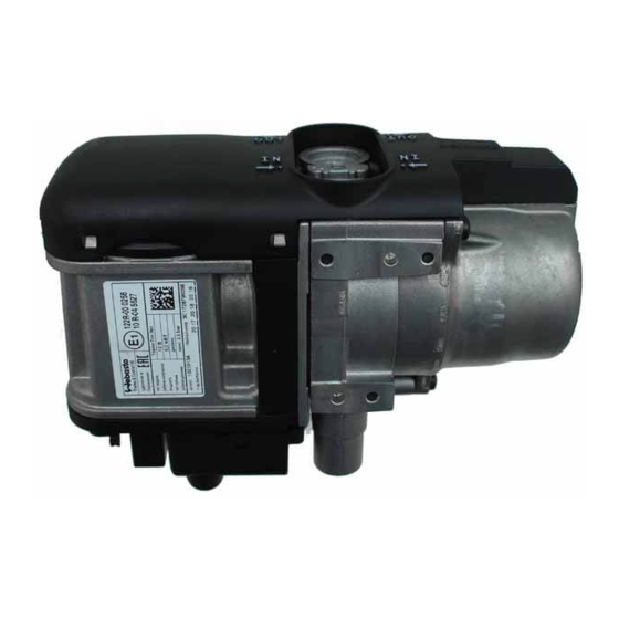
Water Heater
Thermo Top Evo Parking Heater
Installation Documentation
Audi A4 / A5
Validity
Manufacturer
Audi
Motorisation
Fuel
1.8 TFSI
Petrol
1.8 TFSI
Petrol
2.0 TFSI
Petrol
2.0 TFSI
Petrol
2.0 TFSI quattro
Petrol
2.0 TDI
Diesel
2.0 TDI
Diesel
Manufacturer
Audi
Motorisation
Fuel
1.8 TFSI
Petrol
1.8 TFSI
Petrol
2.0 TFSI
Petrol
2.0 TFSI
Petrol
2.0 TFSI quattro
Petrol
2.0 TDI
Diesel
2.0 TDI
Diesel
SG = manual transmission
from Model Year 2008
Left-hand drive vehicle
Verified equipment variants: Automatic air-conditioning
Not verified:
Necessary time for com-
plete installation:
Ident. No.: 1318638A_EN
00 0258
Model
A4
Transmission type Output in kW
SG
SG
SG
Multitronic
S-tronic
S-tronic
S-tronic
Model
A5
Transmission type Output in kW
SG
Multitronic
SG
Multitronic
S-tronic
S-tronic
S-tronic
Front fog light
Xenon / Headlight washer system
Passenger compartment monitoring
Manual air-conditioning system
approx. 7 hours
Status: 24.09.2012
e1
Type
EG-BE-No. / ABE
B8
e1 * 2001 / 116 * 0430 * ...
Displacement in
cm³
118
1798
125
1798
155
1984
155
1984
155
1984
105
1968
130
1968
Type
EG-BE No. / ABE
B8
e1 * 2001 / 116 * 0430 * ...
Displacement in
cm³
125
1798
125
1798
155
1984
155
1984
155
1984
105
1968
130
1968
Engine code
CABB
CJEB
CDNC
CDNC
CDNC
CAGA
CGLC
Engine code
CJEB
CJEB
CDNC
CDNC
CDNC
CAGA
CGLC
© Webasto Thermo & Comfort SE
Advertisement
Table of Contents

Related Manuals for Webasto Thermo Top Evo


Summary of Contents for Webasto Thermo Top Evo
-
Page 1: Validity
Water Heater Thermo Top Evo Parking Heater 00 0258 Installation Documentation Audi A4 / A5 Validity Manufacturer Model Type EG-BE-No. / ABE Audi e1 * 2001 / 116 * 0430 * ... Motorisation Fuel Transmission type Output in kW Displacement in Engine code cm³... -
Page 2: Table Of Contents
Remote Option (Telestart) Necessary Components • Thermo Top Evo basic delivery scope in accordance with the price list • Installation kit for Audi A4 / A5 2008 Petrol and diesel 1318637A • Heater control in accordance with price list and upon consultation with final customer •... -
Page 3: Information On Operating And Installation Instructions
Installation and repair may ONLY be carried out by persons trained and VEHICLE INSTALLATION REQUIREMENTS certified in a Webasto training course. NEVER try to install or repair We- 2.1. Scope basto heating or cooling systems if you have not completed a Webasto training course, you do not have the necessary technical skills and you 2.1.1. -
Page 4: Information On Validity
• Hose clamping pliers • Drilling depth limiter • 60mm dia. stepped drill bit • Metric thread-setter kit • Webasto Thermo Test diagnosis with current software Measurements • All measurements are in mm! Tightening torque values • Tightening torque values of 5x13 heater bolts = 8Nm •... -
Page 5: Preliminary Work
- Remove years that do not apply from the type and duplicate label. - Attach the duplicate label (type label) visibly in the appropriate place in the engine compartment. Heater Installation Location 1 Heater Installation location Ident. No.: 1318638A_EN Status: 24.09.2012 © Webasto Thermo & Comfort SE... -
Page 6: Electrical System Fuse Holder Engine Compartment
Audi A5 / A5 Cabrio 1 Angle bracket 2 Original vehicle stud bolt, M6 nut 3 M5x16 bolt, washer [2x], nut 4 Fuses F1-2 (replace 30A fuse F2 with 3A fuse) Ident. No.: 1318638A_EN Status: 24.09.2012 © Webasto Thermo & Comfort SE... -
Page 7: Electrical System Wiring Harness Routing
Earth wire Positive wire 1 Earth wire on original vehicle earth support 1 Positive wire on positive distributor of cool- point ant reservoir Ident. No.: 1318638A_EN Status: 24.09.2012 © Webasto Thermo & Comfort SE... -
Page 8: Fan Controller
Replace 30A with 3A fuse. Insulate wire end and tie back Cutting point Wiring colours may vary. Loosen M6x16 bolt [6x, see markings] Removing the glove compart- ment Ident. No.: 1318638A_EN Status: 24.09.2012 © Webasto Thermo & Comfort SE... - Page 9 Connection to 20-pin connector 1 of A/C con- trol unit Pin 3. Crimp socket contact onto green/white (gn/ws) wire and insert into socket of Pin 3. Connec- tion of A/C control unit Ident. No.: 1318638A_EN Status: 24.09.2012 © Webasto Thermo & Comfort SE...
-
Page 10: Digital Timer
2 M5x16 bolt, washer [2x], M5 self-retain- Installing ing nut receiver 1 Antenna Installing antenna Temperature sensor T100 HTM Fasten temperature sensor 1 with adhesive tape. Installing tempera- ture sensor Ident. No.: 1318638A_EN Status: 24.09.2012 © Webasto Thermo & Comfort SE... -
Page 11: Preparing Installation Location
1 Attach wiring harness of circulating pump 2 M6x25 bolt, flanged nut 3 Bracket section 1 4 Circulating pump 5 Mounting of circulating pump 6 25mm dia. rubber-coated p-clamp Mounting circulating pump Ident. No.: 1318638A_EN Status: 24.09.2012 © Webasto Thermo & Comfort SE... - Page 12 In case of vehicles with additional air intake on the air filter box, twist the combustion air silencer 1 with clamp 2 . Aligning combus- tion air si- lencer Ident. No.: 1318638A_EN Status: 24.09.2012 © Webasto Thermo & Comfort SE...
- Page 13 H = 18x20 mm dia. straight mould- ed hose Hose Z = 20x20mm dia. 90° moulded hose (only for vehicles with ad- Cutting ditional circulating pump) hoses to length A = 1210 G = 1430 Ident. No.: 1318638A_EN Status: 24.09.2012 © Webasto Thermo & Comfort SE...
- Page 14 Align bracket section 2 to be in parallel with bracket section 1 1 Self-tapping bolt 5x13 2 Bracket section 2 3 Bracket section 1 Installing bracket section 2 Ident. No.: 1318638A_EN Status: 24.09.2012 © Webasto Thermo & Comfort SE...
-
Page 15: Installing Heater
1 90° hose section, 10 mm dia. clamp [2x] 2 Fuel line Installing fuel line Installing Heater 1 M8x20 bolt [3x], spring lockwasher [3x] Installing heater 1 Wiring harness of heater [2x] Attaching wiring har- ness Ident. No.: 1318638A_EN Status: 24.09.2012 © Webasto Thermo & Comfort SE... -
Page 16: Fuel
Pull wiring harness of metering pump and fuel line into 10mm dia., 1130mm long corrugated tube 1 . Installing lines 1 Wiring harness of metering pump and fuel line in corrugated tube Installing lines Ident. No.: 1318638A_EN Status: 24.09.2012 © Webasto Thermo & Comfort SE... - Page 17 Installing lines 1 9.1 mm dia. hole; Rivet nut Installing rivet nut 1 Mounting for metering pump 2 Metering pump 3 Support angle 4 M6x25 bolt Installing metering pump Ident. No.: 1318638A_EN Status: 24.09.2012 © Webasto Thermo & Comfort SE...
- Page 18 25.5 mm and drill out connection piece 1 Fuel ex- at centre. Do no drill through side wall! traction 1 Fuel standpipe 2 10mm dia. clamp Installing fuel stand- pipe Ident. No.: 1318638A_EN Status: 24.09.2012 © Webasto Thermo & Comfort SE...
- Page 19 Mount standpipe 1 in hose section 3 and fas- ten with 10mm dia. clamp 2 (between the beads). Cut standpipe 1 to length at the end at an angle. Ident. No.: 1318638A_EN Status: 24.09.2012 © Webasto Thermo & Comfort SE...
- Page 20 Drill out connection piece 2 at centre with 2.0 mm dia. drill bit. Fuel ex- traction Cut retaining clamp 1 at marking. 2 Discard section Cutting re- taining clamp Ident. No.: 1318638A_EN Status: 24.09.2012 © Webasto Thermo & Comfort SE...
- Page 21 3 . Check the position of the components; adjust if necessary. Check that they have freedom of movement. Connect- ing meter- 1 Hose section, 10 mm dia. clamp [2x] ing pump Ident. No.: 1318638A_EN Status: 24.09.2012 © Webasto Thermo & Comfort SE...
-
Page 22: Coolant Circuit Vehicle With Additional Circulating Pump
= 25 mm dia. 2 = Original vehicle spring clip 1 = Original vehicle circulating pump (depends on equipment, not installed in every vehicle). All connecting pipes without a specific designation = 18x18 mm dia. Ident. No.: 1318638A_EN Status: 24.09.2012 © Webasto Thermo & Comfort SE... -
Page 23: Coolant Circuit Vehicle Without Additional Circulating Pump
Ø 27 All spring clips without a specific designation = 25 mm dia. 1 = Original vehicle spring clip All connecting pipes without a specific designation = 18x18 mm dia. Ident. No.: 1318638A_EN Status: 24.09.2012 © Webasto Thermo & Comfort SE... - Page 24 1 M6x20 bolt, spring lockwasher 2 Perforated bracket Installing perforated bracket Mount premounted p-clamp 1 to existing hole. 2 M6x20 bolt, washer, flanged nut Installing rubber- coated p- clamp Ident. No.: 1318638A_EN Status: 24.09.2012 © Webasto Thermo & Comfort SE...
- Page 25 Connec- tion of heat exchanger inlet Route hose A below premounted perforated bracket 1 . Routing in engine compart- ment Ident. No.: 1318638A_EN Status: 24.09.2012 © Webasto Thermo & Comfort SE...
- Page 26 Route hose G through rubber-coated p- clamp 3 and grommet 2 up to the heat ex- changer in the coolant reservoir. 1 200mm long heat protection hose Routing in engine compart- ment Ident. No.: 1318638A_EN Status: 24.09.2012 © Webasto Thermo & Comfort SE...
- Page 27 Vehicles without additional circulating pump Remove original vehicle hose 2 from connec- tion piece of heat exchanger inlet and turn to the right. Clamp 1 will be reused. Cutting point Ident. No.: 1318638A_EN Status: 24.09.2012 © Webasto Thermo & Comfort SE...
- Page 28 All vehicles Figure shows vehicle with additional circulat- ing pump. Align hoses. Ensure sufficient dis- tance to neighbouring components, adjust, if necessary. Inserting hose 1 Hose bracket bracket Ident. No.: 1318638A_EN Status: 24.09.2012 © Webasto Thermo & Comfort SE...
-
Page 29: Exhaust Gas
Ensure suffi- cient distance to neighbouring components, adjust, if necessary. 1 Mount underride protection Aligning 2 Centrally position exhaust end section in exhaust hole end section Ident. No.: 1318638A_EN Status: 24.09.2012 © Webasto Thermo & Comfort SE... -
Page 30: Final Work
Set channel 17 - value from " 0 " to " 1 " Save Webasto Thermo & Comfort SE Postfach 1410 82199 Gilching Germany Internet: www.webasto.com Technical Extranet: http://dealers.webasto.com Ident. No.: 1318638A_EN Status: 24.09.2012 © Webasto Thermo & Comfort SE... -
Page 31: Operating Instructions For Automatic A/C
Audi A4 / A5 Operating Instructions for Automatic A/C Please remove page and add to the vehicle operating instructions. Note: We recommend matching the heating time to the driving time. Heating time = driving time Example: For a driving time of approx. 20 min. (in one direction), we recommend not exceeding a switch-on time of 20 min. - Page 32 Audi A4 / A5 Audi A4 from 2012 model year 1 20A heater fuse F1 2 3A passenger compartment main fuse F2 Fuses of engine compart- ment Audi A5 / A5 Cabrio 1 20A heater fuse F1 2 3A passenger compartment main fuse F2 Fuses of engine compart-...
Need help?
Do you have a question about the Thermo Top Evo and is the answer not in the manual?
Questions and answers