Webasto Thermo Top Evo Installation Documentation
Opel astra parking water heater
Hide thumbs
Also See for Thermo Top Evo:
- User manual ,
- Installation documentation (64 pages) ,
- Manual (57 pages)
Table of Contents
Advertisement
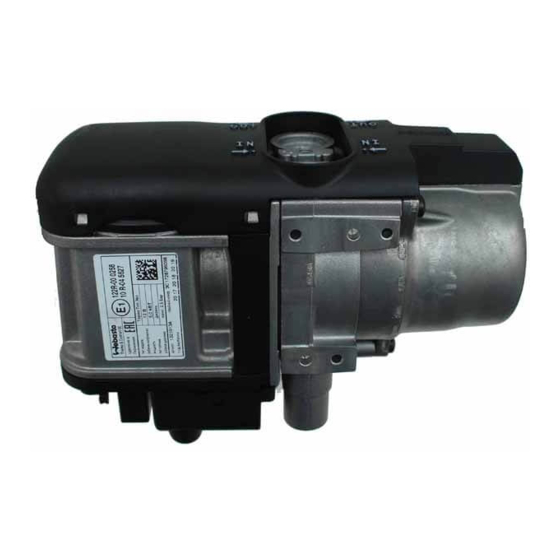
Water Heater
Thermo Top Evo Parking Heater
Installation Documentation
Opel Astra
Validity
Manufacturer
Opel
Opel
Opel
Opel
Motorisation
Fuel
1.4 B
Petrol
1.4 B
Petrol
1.4 B
Petrol
1.6 B
Petrol
1.7D
Diesel
1.7D
Diesel
1.7D
Diesel
1.7D
Diesel
2.0D
Diesel
2.0D
Diesel
2.0D
Diesel
SG = Manual transmission
AT = Automatic transmission
from Model Year 2011
Left-hand drive vehicle
Verified equipment variants: Manual / automatic air-conditioning system
Ident. No.: 1319153A
00 0258
Check NEW UPDATES
Model
Astra
Astra
Astra
Astra
Transmission type Output in kW
6-speed SG
6-speed SG
6-level AT
6-speed SG
6-speed SG
6-speed SG
6-speed SG
6-speed SG
6-speed SG
6-level AT
6-level SG
Front fog light
Start-Stop
Status: 02.01.2013
E
1
www.ifz-berlin.de
Type
EG-BE-No. / ABE
P-J
e1 * 2007 / 46 * 0141 * ...
P-J
e4 * 2007 / 46 * 0204 *...
P-J
e4 * 2007 / 46 * 0308 *...
P-J
e4 * 2007 / 46 * 0309 *...
Displacement in cm³ Engine code
88
1362
103
1362
103
1362
132
1598
81
1686
81
1686
96
1686
96
1686
121
1956
121
1956
143
1956
8,5 h
A14NEL
A14NET
A14NET
A16LET
A17DTC
A17DTE
A17DTS
A17DTF
A20DTH
A20DTH
A20DTR
© Webasto Thermo & Comfort SE
Advertisement
Table of Contents

Related Manuals for Webasto Thermo Top Evo


Summary of Contents for Webasto Thermo Top Evo
-
Page 1: Validity
Water Heater Thermo Top Evo Parking Heater 00 0258 www.ifz-berlin.de Check NEW UPDATES 8,5 h Installation Documentation Opel Astra Validity Manufacturer Model Type EG-BE-No. / ABE Opel Astra e1 * 2007 / 46 * 0141 * ... Opel Astra e4 * 2007 / 46 * 0204 *... -
Page 2: Table Of Contents
Preparing Heater Installing Heater Necessary Components • Specific delivery scope of Thermo Top Evo Petrol or diesel: GM parts No. for petrol: 13 437 784 GM parts No. for Diesel: 13 437 785 • Installation kit Opel Astra 2011 Petrol and diesel GM parts No.: 13 437 791... -
Page 3: Information On Operating And Installation Instructions
Installation and repair may ONLY be carried out by persons trained and VEHICLE INSTALLATION REQUIREMENTS certified in a Webasto training course. NEVER try to install or repair We- 2.1. Scope basto heating or cooling systems if you have not completed a Webasto training course, you do not have the necessary technical skills and you 2.1.1. -
Page 4: Notes On Validity
• Crimping pliers for cable lug / tab connector 0.5 - 6mm² • Torque wrench for 2.0 - 10 Nm • Hose clamping pliers • Webasto Thermo Test diagnosis with current software Dimensions • All dimensions are in mm. Tightening torque values •... -
Page 5: Preliminary Work
• Remove the A-pillar trim on the front passenger's side. Heater • Remove years that do not apply from the type and duplicate label. Heater Installation Location Image shows diesel vehicle. 1 Heater Installation location Ident. No.: 1319153A Status: 02.01.2013 © Webasto Thermo & Comfort SE... -
Page 6: Preparing Electrical System
Glue 400mm of foam 1 around antenna cable 2. Preparing antenna Lump together wiring harness of temperature sensor 2 at position 1 and fasten it using ca- ble tie 3. Preparing tempera- ture sensor Ident. No.: 1319153A Status: 02.01.2013 © Webasto Thermo & Comfort SE... - Page 7 (assigned 3x) ing wiring harness of passen- ger com- partment Glue 40mm of foam 1 around connector of temperature sensor. Preparing wiring har- ness of passen- ger com- partment Ident. No.: 1319153A Status: 02.01.2013 © Webasto Thermo & Comfort SE...
- Page 8 Complete connector of metering pump again after routing. Pin assignment is not relevant. 1 Connector housing 2 Lock 3 Blue/brown (bl / br) wires Removing 4 Coding connector 5 Timer lock Ident. No.: 1319153A Status: 02.01.2013 © Webasto Thermo & Comfort SE...
-
Page 9: Preparing Installation Location
1. Preparing coolant reservoir 1 20mm dia. hole Hole in fire- wall Cut out insulation mat 1 at position 2. Cutting out insulation Ident. No.: 1319153A Status: 02.01.2013 © Webasto Thermo & Comfort SE... - Page 10 2 Drill out hole to 18mm dia. Preparing coolant reservoir 1 6mm dia. hole, insert hole cable tie [3x] Preparing coolant reservoir Cut out coolant reservoir cap 1 at the mark- ing. Preparing coolant reservoir Ident. No.: 1319153A Status: 02.01.2013 © Webasto Thermo & Comfort SE...
-
Page 11: Preparing Heater
2.0 D Discard section X. Hose A = 180° moulded hose Hose C = 90° moulded hose Cutting B = 410 hoses to C = 610 length Ident. No.: 1319153A Status: 02.01.2013 © Webasto Thermo & Comfort SE... - Page 12 2 Decoupling rubber Preparing bracket 1 Clamping plate part 1 2 Intermediate plate 3 Clamping plate part 2 Preparing bracket 1 Bracket 2 Clamping plate part 1 Preparing bracket Ident. No.: 1319153A Status: 02.01.2013 © Webasto Thermo & Comfort SE...
- Page 13 2 Clamping plate part 2 Preparing bracket 1 5x13 self-tapping bolt [3x] Installing bracket 1 M4x12 bolt, large diameter washer [2x], 2 Retaining plate for fuse holder Installing retaining plate of fuse holder Ident. No.: 1319153A Status: 02.01.2013 © Webasto Thermo & Comfort SE...
- Page 14 Attach wiring harness of circulating pump 1, all vehicles except 2.0l D. 2 Cable tie (wiring harness of metering pump and wiring harness of circulating pump) Installing hoses Ident. No.: 1319153A Status: 02.01.2013 © Webasto Thermo & Comfort SE...
-
Page 15: Installing Heater
2 M8x20 bolt, large diameter washer, exist- Mounting ing hole heater 3 Large diameter washer, flanged nut 1 M8x20 bolt, large diameter washer [2x], flanged nut Mounting heater Ident. No.: 1319153A Status: 02.01.2013 © Webasto Thermo & Comfort SE... -
Page 16: Fuses F2-4
Engine compartment fuse holder Positive and earth wire 1 Fuses F2-4 (will be inserted later) 1 Earth wire at original vehicle earth support point 2 Positive wire on positive support point Ident. No.: 1319153A Status: 02.01.2013 © Webasto Thermo & Comfort SE... -
Page 17: Vehicle-Specific Wiring Harness
Telestart HTM 100 green Legend Temperature sensor grey Push button white Diagnosis connector blue Fuse 30A brown Fuse 30A Fuse 5A Fuse 5A Cutting point Fuse 20A Wiring colours may vary. Ident. No.: 1319153A Status: 02.01.2013 © Webasto Thermo & Comfort SE... - Page 18 2 Cable tie on wiring harness of heater and windscreen wiper linkage Wiring har- ness rout- 1 Wiring harness of heater, hole cable tie [3x] Wiring har- ness rout- Ident. No.: 1319153A Status: 02.01.2013 © Webasto Thermo & Comfort SE...
- Page 19 Replace original vehicle bolt at position 2 with M6x25 bolt and large diameter washer. 1 Detach connector of airbag from bracket. 2 M6x25 bolt, large diameter washer Preparing installation location of SVM-Mod- Ident. No.: 1319153A Status: 02.01.2013 © Webasto Thermo & Comfort SE...
- Page 20 Fasten green/white (gn/ws) wire of SVM- module/OBD-socket outlet 1 to original vehi- cle wiring harness with cable tie. 2 Carrier of instrument panel Wiring har- ness rout- Ident. No.: 1319153A Status: 02.01.2013 © Webasto Thermo & Comfort SE...
- Page 21 1 Green/white (gn/ws) wire of SVM-module 3 Green (gn) wire of OBD-socket outlet, pin 1 Connec- 4 Green (gn) wire of Low Speed Can tion of OBD-sock- et outlet Ident. No.: 1319153A Status: 02.01.2013 © Webasto Thermo & Comfort SE...
-
Page 22: Telestart
Installing T100 HTM temperature sensor Fasten temperature sensor 1 (hidden) with adhesive tape. Installing tempera- ture sensor 1 Antenna (hidden) Mounting antenna Image shows vehicle with panorama window. 1 Antenna Mounting antenna Ident. No.: 1319153A Status: 02.01.2013 © Webasto Thermo & Comfort SE... -
Page 23: Fuel
3 9x13mm hose bracket Routing lines Fasten fuel line and wiring harness of meter- ing pump in corrugated tube 1 to the original vehicle fuel lines with cable tie. Routing lines Ident. No.: 1319153A Status: 02.01.2013 © Webasto Thermo & Comfort SE... - Page 24 Removing fuel Petrol Remove fuel-tank sending unit 1 in accord- ance with manufacturer's instructions. Move label 3 from position 2 to position 3 . Preparing fuel-tank sending unit Ident. No.: 1319153A Status: 02.01.2013 © Webasto Thermo & Comfort SE...
- Page 25 2 90° moulded hose, 10 mm dia. clamp [2x] 3 Fuel line Installing fuel stand- pipe Fasten fuel line 1 to original vehicle fuel lines with cable tie. Routing fuel line Ident. No.: 1319153A Status: 02.01.2013 © Webasto Thermo & Comfort SE...
- Page 26 Check the position of the components; adjust if necessary. Check that they have freedom of movement. 1 10 mm dia. clamp 2 Fuel line Connect- ing meter- ing pump Ident. No.: 1319153A Status: 02.01.2013 © Webasto Thermo & Comfort SE...
-
Page 27: Coolant Circuit 1.4, 1.6 B And 1.7 D
= 27 mm dia. Hose clamp = dia. 28x35mm. All connecting pipes without a specific designation = 20x20mm dia. All hose brackets not desig- nated in the following section = lockable twice 25-27. Ident. No.: 1319153A Status: 02.01.2013 © Webasto Thermo & Comfort SE... - Page 28 1 4.5x27mm hose bracket 2 Brake line Routing in engine compart- ment 1 Coupling of heat exchanger inlet 2 Hose bracket 3 Clamp 28-35 Connect- ing heat ex- changer inlet Ident. No.: 1319153A Status: 02.01.2013 © Webasto Thermo & Comfort SE...
- Page 29 1 8x27mm hose bracket 2 A/C line 3 Fuel line and wiring harness of metering pump in corrugated tube 4 14x27mm hose bracket Routing in engine compart- ment Ident. No.: 1319153A Status: 02.01.2013 © Webasto Thermo & Comfort SE...
- Page 30 2 Engine outlet hose section point 1 Engine outlet hose section Connect- ing engine outlet 1 Coupling of heat exchanger inlet 2 Clamp 28-35 Connect- ing heat ex- changer inlet Ident. No.: 1319153A Status: 02.01.2013 © Webasto Thermo & Comfort SE...
- Page 31 Opel Astra 1 Hose bracket Routing in engine compart- ment 1 Hose bracket [2x] Routing in engine compart- ment Ident. No.: 1319153A Status: 02.01.2013 © Webasto Thermo & Comfort SE...
-
Page 32: Coolant Circuit 2.0 D
All spring clips without a specific designation = 27 mm dia. Hose clamp = dia. 28x35mm. Connecting pipe = 18x20mm dia. All hose brackets not designated in the following section = lock- able twice 25-27. Ident. No.: 1319153A Status: 02.01.2013 © Webasto Thermo & Comfort SE... - Page 33 Cut hose of engine outlet / heat exchanger in- let at the marking. Remove hose section of heat exchanger inlet 1 and discard. 2 Engine outlet hose section Cutting point Ident. No.: 1319153A Status: 02.01.2013 © Webasto Thermo & Comfort SE...
- Page 34 1 Coupling of heat exchanger inlet 2 Clamp 28-35 Connect- ing heat ex- changer inlet 1 Engine outlet hose section 2 Hose bracket [2x] Routing in engine compart- ment Ident. No.: 1319153A Status: 02.01.2013 © Webasto Thermo & Comfort SE...
-
Page 35: Exhaust Gas
2 and belt drive 3 at position 4 . 1 Hose clamp 2 Exhaust pipe Mounting exhaust pipe Insert bracket 1 into hole 2 and align with threaded hole at position 3 . Mounting exhaust end section Ident. No.: 1319153A Status: 02.01.2013 © Webasto Thermo & Comfort SE... - Page 36 2 Bracket of exhaust end section Installing bracket of exhaust end section 1 M6x25 bolt in threaded hole of bracket 2 M6x16 bolt, flanged nut 3 Silencer Installing silencer Ident. No.: 1319153A Status: 02.01.2013 © Webasto Thermo & Comfort SE...
- Page 37 2 60 mm dia. hole Hole in un- derride protection Align exhaust end section 1 in the middle of the hole and flush on underride protection 2 . Aligning exhaust end section Ident. No.: 1319153A Status: 02.01.2013 © Webasto Thermo & Comfort SE...
-
Page 38: Combustion Air
Combustion Air 1 Combustion air pipe 2 Cable tie 3 Silencer 4 25mm dia. Caillau clamp Installing silencer 1 Retaining clip of silencer in hole 2 Cable tie Installing silencer Ident. No.: 1319153A Status: 02.01.2013 © Webasto Thermo & Comfort SE... -
Page 39: Final Work
Transmitter and push button are to be taught prior to insertion of fuse F2 3 . 1 Fuse F4 - 20A 2 Fuse F3 - 5A 3 Fuse F2 - 5A Inserting fuses Ident. No.: 1319153A Status: 02.01.2013 © Webasto Thermo & Comfort SE... -
Page 40: Template For Fuel Standpipe
Compare the size of the printed version with dimension lines. Permitted tolerance a maximum of 2%. Set the printer settings to “no margin” or “minimise mar- gins” and 100% of the normal size. 100mm Ident. No.: 1319153A Status: 02.01.2013 © Webasto Thermo & Comfort SE...
Need help?
Do you have a question about the Thermo Top Evo and is the answer not in the manual?
Questions and answers