Webasto Thermo Top Evo Installation Documentation
Parking heater with fuelfix
Hide thumbs
Also See for Thermo Top Evo:
- User manual ,
- Installation documentation (64 pages) ,
- Manual (57 pages)
Table of Contents
Advertisement
K
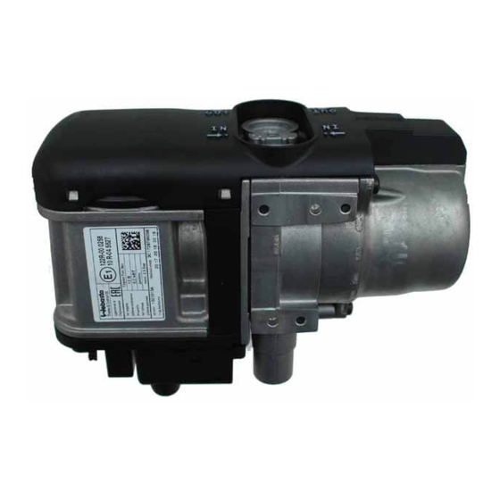
Water Heater
Thermo Top Evo Parking Heater
With FuelFix
Installation Documentation
Ford Mondeo
Validity
Manufacturer
Ford
Motorisation
2.0 TDCi
2.0 TDCi
1.5 EcoBoost
2.0 EcoBoost
AG = automatic transmission
from model year 2015
Left-hand drive vehicle
Verified equipment variants: Automatic air-conditioning
Total installation time:
Ident. No.: 1323975A_EN
Model
Mondeo
Fuel
Transmission type Output in kW
Diesel
AG
Diesel
AG
Petrol
AG
Petrol
AG
2WD / 4WD
Start - Stop
Euro 6
approx. 9 hours
Status: 12.06.2015
E
1
00 0258
Type
CD 4 / BA7
110
132
118
176
EG-BE-No. / ABE
e13 * 2001 / 116 * 0249 * ...
Displacement in cm³ Engine code
1997
T7CE
1997
T8CC
1499
UNCA / UNCB /
UNCE / UNCF
1997
R9CB / R9CF /
R9CH
© Webasto Thermo & Comfort SE
Advertisement
Table of Contents

Related Manuals for Webasto Thermo Top Evo


Summary of Contents for Webasto Thermo Top Evo
-
Page 1: Validity
Water Heater Thermo Top Evo Parking Heater 00 0258 With FuelFix Installation Documentation Ford Mondeo Validity Manufacturer Model Type EG-BE-No. / ABE Ford Mondeo CD 4 / BA7 e13 * 2001 / 116 * 0249 * ... Motorisation Fuel Transmission type Output in kW Displacement in cm³... -
Page 2: Table Of Contents
MultiControl CAR Option Remote Option (Telestart) Thermo Call Option Necessary Components Basic delivery scope of Thermo Top Evo based on price list • Installation kit with FuelFix Ford Mondeo 2015 Petrol and diesel: 1323974A • To be ordered additionally in case of automatic air-conditioning either: •... -
Page 3: Information On Operating And Installation Instructions
To ensure safe operation, we recommend having the heater checked every two years 2.2. Positioning of heater by an authorised Webasto dealer, especially when used over a long period and/or un- der extreme environmental conditions. 2.2.1. Body sections and any other components in the vicinity of the heater must be protected from excessive heat and the possibility of fuel or oil contamination. -
Page 4: Information On Validity
• Crimping pliers for cable lug / tab connector 0.5 - 6mm² • Torque wrench for 2.0 - 10 Nm • Hose clamping pliers • Metric thread-setter kit • Webasto Thermo Test diagnosis with current software Dimensions • All dimensions are in mm Tightening torque values •... -
Page 5: Preliminary Work
• Remove years that do not apply from the type and duplicate label. • Attach the duplicate label (type label) at the appropriate place in the engine compartment. Heater Installation Location 1 Heater Installation location Ident. No.: 1323975A_EN Status: 12.06.2015 © Webasto Thermo & Comfort SE... -
Page 6: Preparing Electrical System
3 13 mm dia., 700 mm long slitted cor- Pulling wir- rugated tube ing har- nesses into corrugated tube Connector X7 Disman- tling con- nector of metering pump Ident. No.: 1323975A_EN Status: 12.06.2015 © Webasto Thermo & Comfort SE... -
Page 7: Electrical System
2 Positive wire on positive distributor 1 Fuses F1-2 2 M6x12 bolt, large diameter washer, original vehicle hole, flanged nut 3 M5x16 bolt, washer [2x], retaining plate of fuse holder, angle bracket, nut Ident. No.: 1323975A_EN Status: 12.06.2015 © Webasto Thermo & Comfort SE... -
Page 8: Multicontrol Car Option
2 Bracket with oblong hole 3 Bracket of receiver View of re- ceiver with bracket 1 Receiver 2 Existing hole, M5x16 bolt, flanged nut Mounting receiver 1 Antenna Mounting antenna Ident. No.: 1323975A_EN Status: 12.06.2015 © Webasto Thermo & Comfort SE... -
Page 9: Thermo Call Option
1 Insulation mat 2 Front passenger's side footwell trim Removing in- sulation mat in shaded area Fasten receiver 1 with adhesive tape. 2 Footwell trim Mounting receiver 1 Antenna Mounting antenna Ident. No.: 1323975A_EN Status: 12.06.2015 © Webasto Thermo & Comfort SE... -
Page 10: Preparing Installation Location
1 Pass through 2 Wiring harness of heater 3 Edge protection Installing wiring har- ness of heater 1 Area for fastening adhesive base Cleaning body sur- face Ident. No.: 1323975A_EN Status: 12.06.2015 © Webasto Thermo & Comfort SE... -
Page 11: Preparing Heater
Hose F = 90°, 15x18 mm dia. moulded hose Cutting hos- es to length All spring clips = 25 mm dia. 1 90°, 18x18mm dia. connecting pipe [2x] Installing hoses Ident. No.: 1323975A_EN Status: 12.06.2015 © Webasto Thermo & Comfort SE... - Page 12 1 Combustion air pipe part a 2 25 mm dia. clamp 3 M5x13 self-tapping bolt in existing hole Mounting combustion air pipe Discard section X. 1 Combustion air silencer Preparing combustion air silencer Ident. No.: 1323975A_EN Status: 12.06.2015 © Webasto Thermo & Comfort SE...
- Page 13 Route corrugated tube with fuel line 4 through pass through 2 into the engine compartment. 1 Connector of circulating pump wiring harness Mounting 3 Connector for wiring harness of heat- wiring har- er [2x] nesses Ident. No.: 1323975A_EN Status: 12.06.2015 © Webasto Thermo & Comfort SE...
-
Page 14: Installing Heater
3 Hose clamp Installing ex- 4 M6x20 bolt, spring lockwasher, large haust sys- diameter washer 1 M6x20 bolt, spring lockwasher, large diameter washer 2 Exhaust system Installing ex- haust sys- Ident. No.: 1323975A_EN Status: 12.06.2015 © Webasto Thermo & Comfort SE... -
Page 15: Fuel
Routing on firewall Route fuel line and metering pump wiring harness 1 on the underbody along original vehicle wiring harness to the installation location of the metering pump. Routing lines Ident. No.: 1323975A_EN Status: 12.06.2015 © Webasto Thermo & Comfort SE... -
Page 16: Fuelfix Installation For Diesel Vehicles
1 Hole made with provided drill Hole for FuelFix Work step 4 and 5. Bend FuelFix 1 according to template and cut to length. Insert in hole 2. Inserting FuelFix Ident. No.: 1323975A_EN Status: 12.06.2015 © Webasto Thermo & Comfort SE... - Page 17 Work step 5.4. Align FuelFix 1 as shown by turning. Aligning FuelFix Work step 6. 1 Hose section, 10mm dia. clamp [2x] 2 Fuel line 3 FuelFix Connect- ing fuel line Ident. No.: 1323975A_EN Status: 12.06.2015 © Webasto Thermo & Comfort SE...
- Page 18 Install tank 3 according to the manufactur- er's instructions. Route FuelFix fuel line 2 along original ve- hicle wiring harness and secure with cable tie 1 [3x] as tension relief . Routing fuel line Ident. No.: 1323975A_EN Status: 12.06.2015 © Webasto Thermo & Comfort SE...
-
Page 19: Fuelfix Installation For Petrol Vehicles
Bend FuelFix 1 according to template and cut to length. Insert in hole 2. Inserting FuelFix Work step 5. 1 FuelFix Inserting FuelFix Work step 5. 1 FuelFix Inserting FuelFix Ident. No.: 1323975A_EN Status: 12.06.2015 © Webasto Thermo & Comfort SE... - Page 20 F 7.6. Work step 8. Ensure firm seating of FuelFix and posi- tioning of clamping piece 2 with respect to upper edge 1 of the housing. Checking fi- nal position Ident. No.: 1323975A_EN Status: 12.06.2015 © Webasto Thermo & Comfort SE...
- Page 21 4 90° moulded hose, 10 mm dia. clamp metering pump 1 Support angle bracket, M6x25 bolt, original vehicle hole, flanged nut 2 Metering pump 3 Mounting of metering pump Mounting metering pump Ident. No.: 1323975A_EN Status: 12.06.2015 © Webasto Thermo & Comfort SE...
- Page 22 Ensure sufficient distance from neighbour- ing components, correct if necessary. Connect- 3 Wiring harness of metering pump, ing meter- connector X7 mounted ing pump 5 Hose section, 10 mm dia. clamp Ident. No.: 1323975A_EN Status: 12.06.2015 © Webasto Thermo & Comfort SE...
-
Page 23: Coolant Circuit
Hose rout- ing diagram Ø 23 All spring clips without a specific designation = 25 mm dia. 1 = Original vehicle spring clip All connecting pipes = 18x18mm dia. Ident. No.: 1323975A_EN Status: 12.06.2015 © Webasto Thermo & Comfort SE... - Page 24 Cutting point 1 28 mm dia., 500 mm heat protection hose [2x] Premount- ing hoses 1 Spring clip Connect- ing heat ex- changer inlet Connect- ing heater outlet Ident. No.: 1323975A_EN Status: 12.06.2015 © Webasto Thermo & Comfort SE...
- Page 25 2 Mounting circulating pump 3 Angle bracket 4 Original vehicle stud bolt, M6 plastic Aligning circulating pump 1 Wiring harness circulating pump 2 Cable tie Connect- ing heater inlet Ident. No.: 1323975A_EN Status: 12.06.2015 © Webasto Thermo & Comfort SE...
- Page 26 1 Original vehicle spring clip 2 Hose of engine outlet Connect- ing engine outlet 1 Circulating pump 2 Connector of circulating pump wiring harness Connect- ing wiring harness of circulating pump Ident. No.: 1323975A_EN Status: 12.06.2015 © Webasto Thermo & Comfort SE...
- Page 27 2 Perforated bracket 3 M6 plastic nut, original vehicle stud bolt 4 Original vehicle bolt Mounting original ve- hicle relay 1 Wheel-well inner panel 2 Insulation Removing insulation in shaded area Ident. No.: 1323975A_EN Status: 12.06.2015 © Webasto Thermo & Comfort SE...
- Page 28 • Place the "Switch off parking heater before refuelling" caution label in the area of the filler neck. • See installation instructions for initial startup and function check. Webasto Thermo & Comfort SE Postfach 1410 82199 Gilching Germany Internet: www.webasto.com Technical Extranet: http://dealers.webasto.com Ident. No.: 1323975A_EN Status: 12.06.2015 © Webasto Thermo & Comfort SE...
-
Page 29: Fuelfix Template For Diesel And Petrol Vehicles
Compare size of the printed version with dimension lines. Allowed tolerance max. 2%. Set the printer settings to “no margin” or “minimise mar- gins” and 100% of the normal size. 100mm Ident. No.: 1323975A_EN Status: 12.06.2015 © Webasto Thermo & Comfort SE...
Need help?
Do you have a question about the Thermo Top Evo and is the answer not in the manual?
Questions and answers