Webasto Thermo Top Evo Installation Documentation
Toyota lc 200
Hide thumbs
Also See for Thermo Top Evo:
- User manual ,
- Installation documentation (64 pages) ,
- Manual (57 pages)
Table of Contents
Advertisement
Quick Links
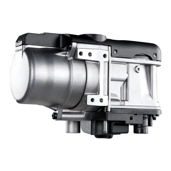
Water Heater
Thermo Top Evo Parking Heater
Installation documentation
Toyota LC 200
Validity
Manufacturer
Toyota
Motorisation
Fuel
4.5 V8
Diesel
AT = automatic transmission
From Model Year 2012
Left-hand drive vehicle
Verified equipment vari-
ants:
WARNING!
Mind specific water connection with TT-EVO 4 without engine preheating.
Preheating the engine is not recommended and can cause starting problems and / or error messages.
Total installation time:
Ident. No.: 1318445A_EN
00 0258
Model
Landcruiser V8
Transmission type Output in kW
6-speed AT
Front and rear air-conditioning
Front fog light
Alarm system
4 WD
Bi Xenon headlights with headlight washer system
Start button, smart key
approx. 9 hours
Status: 18.09.2012
e1
Type
EG-BE No. / ABE
J20 (A)
e6 * 2001 / 116 * 0112 * ...
Displacement in
cm³
200
4461
Engine code
1VD-FTV
© Webasto Thermo & Comfort SE
Advertisement
Table of Contents

Subscribe to Our Youtube Channel
Related Manuals for Webasto Thermo Top Evo


Summary of Contents for Webasto Thermo Top Evo
-
Page 1: Validity
Water Heater Thermo Top Evo Parking Heater 00 0258 Installation documentation Toyota LC 200 Validity Manufacturer Model Type EG-BE No. / ABE Toyota Landcruiser V8 J20 (A) e6 * 2001 / 116 * 0112 * ... Motorisation Fuel Transmission type Output in kW... -
Page 2: Table Of Contents
Digital Timer Remote Option (Telestart) Necessary Components • Standard delivery scope Thermo Top Evo 4 in accordance with price list • Installation kit for Toyota LC 200 2012 Diesel 1318444A • Heater control in accordance with price list and upon consultation with end customer •... -
Page 3: Information On Operating And Installation Instructions
Installation and repair may ONLY be carried out by persons trained and VEHICLE INSTALLATION REQUIREMENTS certified in a Webasto training course. NEVER try to install or repair We- 2.1. Scope basto heating or cooling systems if you have not completed a Webasto training course, you do not have the necessary technical skills and you 2.1.1. -
Page 4: Information On Validity
• Crimping pliers for cable lug / tab connector 0.5 - 6mm² • Torque wrench for 2.0 - 10 Nm • Hose clamping pliers • 60mm dia. hole saw • Webasto Thermo Test Diagnosis with current software Dimensions • All dimensions are in mm Tightening torque values •... -
Page 5: Preliminary Work
• Remove years that do not apply from the type and duplicate label. • Attach the duplicate label (type label) in the appropriate place in the engine compartment. Heater Installation Location 1 Heater Installation location Ident. No.: 1318445A_EN Status: 18.09.2012 © Webasto Thermo & Comfort SE... -
Page 6: Preparing Electrical System
Insert 10A fuse F4. 0,5² 4² 0,75² Wiring dia- gram of passenger gn/ws compart- 0,75² ment fuse holder 4² 0,5² 0,5² IPCU 4² 0,5² 0,5² 0,75² 0,75² 0,5² 0,75² 0,75² Ident. No.: 1318445A_EN Status: 18.09.2012 © Webasto Thermo & Comfort SE... - Page 7 K2 relay 3 after assembly. 1 M5x16 bolt, washer [2x], passenger com- partment fuse holder, nut Preparing 4 Perforated bracket fuse holder of passen- ger com- partment Ident. No.: 1318445A_EN Status: 18.09.2012 © Webasto Thermo & Comfort SE...
-
Page 8: Holder
Complete metering pump connector again af- ter routing. Pin assignment is not relevant. 1 Connector housing 2 Lock 3 Blue (bl) / brown (br) wires Disman- 4 Coding tling con- 5 Timer lock nector Ident. No.: 1318445A_EN Status: 18.09.2012 © Webasto Thermo & Comfort SE... -
Page 9: Electrical System
Fuse holder of engine compartment Positive wire Align fuses, tighten bolt 3 . 1 Positive wire on positive battery terminal 1 Angle bracket 2 M6x20 bolt, flanged nut, existing hole 4 Diagnosis connector Ident. No.: 1318445A_EN Status: 18.09.2012 © Webasto Thermo & Comfort SE... -
Page 10: Front Air-Conditioning Fan Controller
1A fuse 10 A fuse IPCU Pulse width modulator IPCU adjustment values: Duty cycle: 60% Frequency: 400 Hz Voltage: 10 V Cutting point Function: Low-side Wiring colours may vary. Ident. No.: 1318445A_EN Status: 18.09.2012 © Webasto Thermo & Comfort SE... -
Page 11: Front And Rear Air-Conditioning Fan Controller
Plug connection 10 A fuse IPCU Pulse width modulator IPCU adjustment values: Duty cycle: 60% Frequency: 400 Hz Voltage: 10 V Cutting point Function: Low-side Wiring colours may vary. Ident. No.: 1318445A_EN Status: 18.09.2012 © Webasto Thermo & Comfort SE... - Page 12 1 Green (gn) wire to connector E81 (C) Pin 1 ing A/C 3 Green (gn) wire of fuse IGN booster Red (rt) wire of K1/87a Black (sw) wire of K1/30 Ident. No.: 1318445A_EN Status: 18.09.2012 © Webasto Thermo & Comfort SE...
- Page 13 E36 (B) 8 9 10 11 12 13 14 15 16 17 18 19 20 21 22 23 24 25 26 27 28 29 30 31 32 33 34 35 Ident. No.: 1318445A_EN Status: 18.09.2012 © Webasto Thermo & Comfort SE...
-
Page 14: Digital Timer
Remote Option (Telestart) Fasten receiver 1 with adhesive tape. Mounting receiver 1 Antenna Mounting antenna Temperature sensor T100 HTM Fasten temperature sensor 1 with adhesive tape. Mounting tempera- ture sensor Ident. No.: 1318445A_EN Status: 18.09.2012 © Webasto Thermo & Comfort SE... -
Page 15: Preparing Installation Location
1 7mm dia. hole, M6x12 bolt, pin lock [3x each] 2 M6x12 bolt, large diameter washer, pin lock Installing bolts 1 60mm dia. hole Hole in cross member 1 210mm edge protection Inserting edge pro- tection Ident. No.: 1318445A_EN Status: 18.09.2012 © Webasto Thermo & Comfort SE... -
Page 16: Preparing Heater
Hose J = 180°, 18 mm dia. moulded hose Cutting hoses to length 1 18x18mm dia. 90° connecting pipe, 25mm dia. spring clip [2x each] Preparing hoses A and F Ident. No.: 1318445A_EN Status: 18.09.2012 © Webasto Thermo & Comfort SE... -
Page 17: Installing Heater
1 Tighten 5x13 self-tapping bolt [2x] Mounting heater 1 Tighten 5x13 self-tapping bolt [2x] Mounting heater 1 Wiring harness of heater [2x] 2 Wiring harness of circulating pump Attaching wiring harnesses Ident. No.: 1318445A_EN Status: 18.09.2012 © Webasto Thermo & Comfort SE... -
Page 18: Combustion Air
1 Combustion air pipe Mounting combus- tion air pipe 1 M5x16 bolt, large diameter washer, flanged nut, existing hole 2 Silencer 3 Combustion air pipe 4 51 mm dia. clamp Installing silencer Ident. No.: 1318445A_EN Status: 18.09.2012 © Webasto Thermo & Comfort SE... -
Page 19: Exhaust Gas
Angling down per- forated 70° bracket 90° 90° 1 Silencer 2 M6x16 bolt, spring lockwasher 3 Perforated bracket Premount- ing silencer 1 7mm dia. hole [2x] Holes in bumper Ident. No.: 1318445A_EN Status: 18.09.2012 © Webasto Thermo & Comfort SE... - Page 20 1 M6x20 bolt, flanged nut [2x] 2 Perforated bracket Installing silencer 1 Hose clamp [2x] 2 Exhaust pipe Mounting exhaust pipe 1 Hose clamp 2 Exhaust end section Mounting end section Ident. No.: 1318445A_EN Status: 18.09.2012 © Webasto Thermo & Comfort SE...
-
Page 21: Fuel
Route fuel line and wiring harness of meter- ing pump in 10mm dia. corrugated tube 1 along original vehicle brake lines to installa- tion location of metering pump. Routing lines Ident. No.: 1318445A_EN Status: 18.09.2012 © Webasto Thermo & Comfort SE... - Page 22 Connect- 5 Hose section [2x], 10 mm dia. clamp [4x] ing meter- ing pump 1 Fuel line and fuel standpipe in 10mm dia. corrugated tube Routing lines Ident. No.: 1318445A_EN Status: 18.09.2012 © Webasto Thermo & Comfort SE...
- Page 23 Check that they have freedom of movement. 2 10x5x10 fuel standpipe, 12mm dia. Fuel ex- clamp [2x] traction 3 Hose section, 10 mm dia. clamp [2x] 4 Fuel line Ident. No.: 1318445A_EN Status: 18.09.2012 © Webasto Thermo & Comfort SE...
-
Page 24: Front Air-Conditioning Coolant Circuit
= 25 mm dia. 4 = Black (sw) rubber isolator . 1 = Check valve 2x18mm dia. All connecting pipes = 18x18 mm dia. 2 = Check valve 3x18mm dia. 3 = T-piece Ident. No.: 1318445A_EN Status: 18.09.2012 © Webasto Thermo & Comfort SE... -
Page 25: Front And Rear Air-Conditioning Coolant Circuit
. 1 = Check valve 2x18mm dia. 5 = Connection of rear heat exchanger All connecting pipes = 18x18 mm dia. 2 = Check valve 3x18mm dia. ! 3 = T-piece Ident. No.: 1318445A_EN Status: 18.09.2012 © Webasto Thermo & Comfort SE... - Page 26 2 . Align 90° connect- ing pipe in 60mm dia. hole. 2 25mm dia. rubber-coated p-clamp mounted on original vehicle stud bolt Routing in engine compart- ment Ident. No.: 1318445A_EN Status: 18.09.2012 © Webasto Thermo & Comfort SE...
- Page 27 4 M6x20 bolt, flanged nut Fastening hoses 1 Original vehicle stud bolt 2 M6x30 spacer nut 3 M6x16 bolt, spring lockwasher 4 25 mm dia. rubber-coated p-clamp Hose mounting Ident. No.: 1318445A_EN Status: 18.09.2012 © Webasto Thermo & Comfort SE...
- Page 28 1 M6x20 bolt, flanged nut, existing hole 2 Perforated bracket Installing perforated bracket 1 Mount wiring harness of circulating pump 2 Circulating pump 3 Circulating pump mounting 4 M6x25 bolt, flanged nut Mounting circulating pump Ident. No.: 1318445A_EN Status: 18.09.2012 © Webasto Thermo & Comfort SE...
- Page 29 Cutting 1 Discard section point 2 Hose section of heat exchanger inlet 3 Engine outlet hose section 4 Engine inlet hose section 5 Hose section on heat exchanger outlet Ident. No.: 1318445A_EN Status: 18.09.2012 © Webasto Thermo & Comfort SE...
- Page 30 3 Hose of engine inlet 4 Align black (sw) rubber isolator Installing T- Piece Route hose G through rubber-coated p- clamp. 1 Original vehicle hose bracket 2 Check valve Installing check valve Ident. No.: 1318445A_EN Status: 18.09.2012 © Webasto Thermo & Comfort SE...
- Page 31 1 Hose on heat exchanger inlet Connec- 2 Hose of engine outlet tion of en- gine outlet / heat ex- changer in- Check direction of flow. 1 Check valve 2x18mm dia. Installing check valve Ident. No.: 1318445A_EN Status: 18.09.2012 © Webasto Thermo & Comfort SE...
-
Page 32: Final Work
1/3 of the maximum speed specified by IPCU. • Mount "Switch off parking heater before refueling" signboard in area of filler neck. • During initial start up, proceed as follows with the Webasto Thermo Test Diagnosis: Control coolant pump under Menu Component test, check coolant level ... - Page 33 Toyota LC 200 Webasto Thermo & Comfort SE Postfach 1410 82199 Gilching Germany Internet: www.webasto.com Technical Extranet: http://dealers.webasto.com Ident. No.: 1318445A_EN Status: 18.09.2012 © Webasto Thermo & Comfort SE...
-
Page 34: Operating Instructions For End Customer
2 30A main fuse F2 of passenger compart- ment Fuses of engine compart- ment 1 1A fuse F3 of heater control 2 10A fan fuse F4 Fuses of passenger compart- ment Ident. No.: 1318445A_EN Status: 18.09.2012 © Webasto Thermo & Comfort SE...
Need help?
Do you have a question about the Thermo Top Evo and is the answer not in the manual?
Questions and answers