
Related Manuals for Siemens RVA63.242


Summary of Contents for Siemens RVA63.242
- Page 1 RVA63.242 and RVA53.242 Boiler and Heating Circuit Controllers Basic Documentation Edition 1.3 Controller series B Siemens Building Technologies CE1P2373E Landis & Staefa Division 26.03.2001...
- Page 2 2/218 Siemens Building Technologies Basisdokumentation RVA63.242, RVA53.242 CE1P2373E Landis & Staefa Division 26.03..2001...
-
Page 3: Table Of Contents
Setting the clock ................46 Time of day ..................46 Weekday ..................46 Date (day, month) ................47 Year ....................47 Time switch program 1................ 48 3/218 Siemens Building Technologies Basic Documentation RVA63.242, RVA53.242 CE1P2373E Landis & Staefa Division Contents 26.03.2001... - Page 4 Description of heating engineer settings..........72 Service values ..................72 Output test..................72 Input test ...................73 Display of plant type................74 Actual values..................75 Actual value of flow temperature (B1) ............75 4/218 Siemens Building Technologies Basic Documentation RVA63.242, RVA53.242 CE1P2373E Landis & Staefa Division Contents 26.03.2001...
- Page 5 Minimum limitation of flow temperature setpoint HK2 (TVmin) ....102 4.41 Maximum limitation of flow temperature setpoint HK1 (TVmax)....103 4.42 Maximum limitation of flow temperature setpoint (TVmax) HK2 ....103 5/218 Siemens Building Technologies Basic Documentation RVA63.242, RVA53.242 CE1P2373E Landis & Staefa Division Contents 26.03.2001...
- Page 6 Demand for heat with reduced d.h.w. setpoint........139 Multi-functional inputs................ 140 4.78 Input H1................... 140 4.79 Minimum flow temperature setpoint contact H (TVHw) ......144 6/218 Siemens Building Technologies Basic Documentation RVA63.242, RVA53.242 CE1P2373E Landis & Staefa Division Contents 26.03.2001...
- Page 7 Constant for quick setback and optimum start control (KON)....170 5.23.1 Quick setback without room influence..........171 5.23.2 Optimum start control without influence..........171 5.24 Boost of room temperature setpoint (DTRSA) ........172 7/218 Siemens Building Technologies Basic Documentation RVA63.242, RVA53.242 CE1P2373E Landis & Staefa Division Contents 26.03.2001...
- Page 8 D.h.w. push..................195 6.10 Pump and valve kick ................. 196 6.11 Protection against discharging after d.h.w. heating ........ 196 6.12 Buffer storage tank operation.............. 197 8/218 Siemens Building Technologies Basic Documentation RVA63.242, RVA53.242 CE1P2373E Landis & Staefa Division Contents 26.03.2001...
- Page 9 Supplementary information on the plant types listed.......210 Legend to plant types ................211 Electrical connections ................212 Dimensions ..................213 8.1.1 Panel cut-out ..................213 8.1.2 Combination of controllers ..............213 Technical data..................214 9/218 Siemens Building Technologies Basic Documentation RVA63.242, RVA53.242 CE1P2373E Landis & Staefa Division Contents 26.03.2001...
-
Page 10: Summary
• Protection against boiler overtemperatures (pump overrun) • Adjustable minimum and maximum limitation of boiler temperature (boiler flow temperature) • Burner cycling protection by observing a minimum burner running time 10/218 Siemens Building Technologies Basic Documentation RVA63.242, RVA53.242 CE1P2373E Landis & Staefa Division Summary 26.03.2001... - Page 11 • Logging the number of burner starts of stages 1 and 2 • Logging the flue gas temperature • Display of plant diagram no. Not with RVA53.242 11/218 Siemens Building Technologies Basic Documentation RVA63.242, RVA53.242 CE1P2373E Landis & Staefa Division Summary 26.03.2001...
-
Page 12: Range Of Products
Mains (2 poles) black AGP3S.05D Burner (5 poles) AGP3S.03B Pumps (3 poles) brown AGP3S.03K Actuator (3-poles) green AGP3S.04F Pumps (4 poles) orange Not for RVA53.242 12/218 Siemens Building Technologies Basic Documentation RVA63.242, RVA53.242 CE1P2373E Landis & Staefa Division Summary 26.03.2001... -
Page 13: Field Of Use
“Local Process Bus (LPB), Basic Documentation, System Engineering“ (document no. CE1P2370E) must be satisfied • The local regulations (for installation, etc.) must be complied with 13/218 Siemens Building Technologies Basic Documentation RVA63.242, RVA53.242 CE1P2373E Landis & Staefa Division Summary 26.03.2001... -
Page 14: Handling
• Plug the connectors into the respective sockets at the rear of the controller è Note: The connectors are coded to make certain they cannot be mixed up. 14/218 Siemens Building Technologies Basic Documentation RVA63.242, RVA53.242 CE1P2373E Landis & Staefa Division Handling 26.03.2001... - Page 15 Note: Tighten the screws only slightly, applying a torque of maximum 20 Ncm. When tightening the screws, the fixing levers automatically assume their correct positions. 15/218 Siemens Building Technologies Basic Documentation RVA63.242, RVA53.242 CE1P2373E Landis & Staefa Division Handling 26.03.2001...
-
Page 16: Required Cut-Out
30° and there must be a clearance of at least 10 mm above and below the cooling slots. This allows the controller to emit the heat generated during operation. 16/218 Siemens Building Technologies Basic Documentation RVA63.242, RVA53.242 CE1P2373E Landis & Staefa Division Handling 26.03.2001... -
Page 17: Electrical Installation
2.2.2 Wiring When using prefabricated cables with connectors, the electrical installation is very straightforward, owing to coding. Note Rear of controller Connection terminals of RVA63.242 2373A01 Connection terminals of RVA53.242 2373A10 17/218 Siemens Building Technologies Basic Documentation RVA63.242, RVA53.242... - Page 18 Burner stage 2 Phase burner stage 2 Burner stage 1 Phase burner stage 1 Live AC 230 V (mains connection) AGP3S.02D black Neutral (mains connection) 18/218 Siemens Building Technologies Basic Documentation RVA63.242, RVA53.242 CE1P2373E Landis & Staefa Division Handling 26.03.2001...
-
Page 19: Commissioning
• Note: If no button is pressed for about 8 minutes, the controller will automatically return to the operating mode selected last. 19/218 Siemens Building Technologies Basic Documentation RVA63.242, RVA53.242 CE1P2373E Landis & Staefa Division Handling 26.03.2001... - Page 20 Display The pointer below the symbol indicates the output activated The number indicates the current test step The number indicates the selected setting line 20/218 Siemens Building Technologies Basic Documentation RVA63.242, RVA53.242 CE1P2373E Landis & Staefa Division Handling 26.03.2001...
- Page 21 The selected sensor values are updated within a maximum of 5 seconds. Note An open-circuit is displayed as – – –. A short-circuit is displayed as o o o. 21/218 Siemens Building Technologies Basic Documentation RVA63.242, RVA53.242 CE1P2373E Landis & Staefa Division Handling 26.03.2001...
- Page 22 Display The number indicates the current test step Displayed value of the temperature measured The number indicates the selected setting line 22/218 Siemens Building Technologies Basic Documentation RVA63.242, RVA53.242 CE1P2373E Landis & Staefa Division Handling 26.03.2001...
-
Page 23: Parameter Settings For The End-User
"End-user”. display • Note: If no button is pressed for about 8 minutes, the controller will automatically return to the operating mode selected last. 23/218 Siemens Building Technologies Basic Documentation RVA63.242, RVA53.242 CE1P2373E Landis & Staefa Division Handling 26.03.2001... -
Page 24: Overview Of End-User Parameters
Frost protection setpoint of the room temperature, line 28 Setpoint knob heating circuit Room temperature frost protection setpoint (TRFw) 4...TRRw °C heating circuits 1 and 2 TRRw Line 27 24/218 Siemens Building Technologies Basic Documentation RVA63.242, RVA53.242 CE1P2373E Landis & Staefa Division Handling 26.03.2001... - Page 25 To reset the selected holiday period, press the + and - buttons simultaneously for 3 seconds. Service Indication of BMU error code 0...255 0...255 Error code Indication of faults 0...255 25/218 Siemens Building Technologies Basic Documentation RVA63.242, RVA53.242 CE1P2373E Landis & Staefa Division Handling 26.03.2001...
-
Page 26: Parameter Settings For The Heating Engineer
"Heating engineer”. display è Note: If no button is pressed for about 8 minutes, the controller will automatically return to the operating mode selected last. 26/218 Siemens Building Technologies Basic Documentation RVA63.242, RVA53.242 CE1P2373E Landis & Staefa Division Handling 26.03.2001... -
Page 27: Overview Of Heating Engineer Parameters
-50...+50 °C (TAxged) Composite outside temperature -50...+50 °C (Taxgem) Outside temperature source - -:- / 00.01...14.16 - - . - - No signal 00.01...14.16 Address 27/218 Siemens Building Technologies Basic Documentation RVA63.242, RVA53.242 CE1P2373E Landis & Staefa Division Handling 26.03.2001... - Page 28 Pump function output (K7) 0...7 No function Heating circuit pump D.h.w. circulating pump Electric immersion heater for d.h.w. Solar pump Pump H2 Boiler bypass pump Alarm output 28/218 Siemens Building Technologies Basic Documentation RVA63.242, RVA53.242 CE1P2373E Landis & Staefa Division Handling 26.03.2001...
- Page 29 0 / 1 Inactive Active Gain of locking signal 0...200 Floor curing HK1 0...3 Functional heating Floor curing heating Functional and floor curing heating D.h.w. 29/218 Siemens Building Technologies Basic Documentation RVA63.242, RVA53.242 CE1P2373E Landis & Staefa Division Handling 26.03.2001...
- Page 30 In the segment In the system (if segment address = 0) Automatic summer / winter changeover 0 / 1 Local change Central changeover of all heating circuits 30/218 Siemens Building Technologies Basic Documentation RVA63.242, RVA53.242 CE1P2373E Landis & Staefa Division Handling 26.03.2001...
- Page 31 This line is active only if the unit is addressed as the heat generation master. Also refer to "LPB device address" in Index. This setting is not integrated for RVA53... 31/218 Siemens Building Technologies Basic Documentation RVA63.242, RVA53.242 CE1P2373E Landis & Staefa Division Handling 26.03.2001...
-
Page 32: Parameter Settings For The Oem
Whether correct or incorrect, each push of a button will be adopted as a digit of the code. As a confirmation, the respective digit changes to 1. 32/218 Siemens Building Technologies Basic Documentation RVA63.242, RVA53.242 CE1P2373E Landis & Staefa Division Handling... -
Page 33: Overview Of Oem Parameters
Gain factor of room influence (KORR) 0...20 Constant for quick setback and optimum start 0...20 control (KON) Boost of the room temperature setpoint (DTRSA) 0...20 °C (K) (with boost heating) 33/218 Siemens Building Technologies Basic Documentation RVA63.242, RVA53.242 CE1P2373E Landis & Staefa Division Handling 26.03.2001... - Page 34 Continuously Partly Service Continuous display 0 / 1 Weekday / time of day Actual value of boiler temperature Software version 00.0...99.0 Device operating hours 0...500000 34/218 Siemens Building Technologies Basic Documentation RVA63.242, RVA53.242 CE1P2373E Landis & Staefa Division Handling 26.03.2001...
-
Page 35: Operation
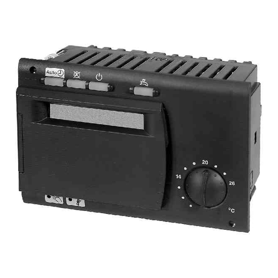
Function button with LED for manual operation Function button with LED for Activation of chimney sweep function chimney sweep Diagnostics and service Connection facility for PC tool 35/218 Siemens Building Technologies Basic Documentation RVA63.242, RVA53.242 CE1P2373E Landis & Staefa Division Handling 26.03.2001... - Page 36 Symbols - indication of operating state with the black pointers Display during normal control mode or when making settings Programming line when making settings Heating program of current day 36/218 Siemens Building Technologies Basic Documentation RVA63.242, RVA53.242 CE1P2373E Landis & Staefa Division Handling 26.03.2001...
-
Page 37: Operational Faults
It must be above the TKmax setting • Check setpoint of the d.h.w. temperature • Check actual value of the d.h.w. temperature • Check if d.h.w. heating is released 37/218 Siemens Building Technologies Basic Documentation RVA63.242, RVA53.242 CE1P2373E Landis & Staefa Division Handling 26.03.2001... - Page 38 • Check the sensor connected to A6 (input test) Fault status signal; display shows "ER" • For cause of error, refer to section "Parameter settings for end-user" on line 50 38/218 Siemens Building Technologies Basic Documentation RVA63.242, RVA53.242 CE1P2373E Landis & Staefa Division Handling 26.03.2001...
-
Page 39: Description Of End-User Settings
• Protective functions active • Changeover on room unit inactive • Automatic summer / winter changeover (ECO functions) and automatic 24-hour heating limit active 39/218 Siemens Building Technologies Basic Documentation RVA63.242, RVA53.242 CE1P2373E Landis & Staefa Division Description of end-user settings 26.03.2001... - Page 40 Changeover of the operating mode on the room unit is active only when the controller is in automatic mode The room temperature is transmitted to the controller via PPS, independent of the selected operating mode. 40/218 Siemens Building Technologies Basic Documentation RVA63.242, RVA53.242 CE1P2373E Landis & Staefa Division Description of end-user settings 26.03.2001...
-
Page 41: Operating Mode Of D.h.w. Heating
• Assignment of d.h.w. heating • Reduced setpoint of the d.h.w. temperature • D.h.w. heating program • D.h.w. heating • Type of d.h.w. demand 41/218 Siemens Building Technologies Basic Documentation RVA63.242, RVA53.242 CE1P2373E Landis & Staefa Division Description of end-user settings 26.03.2001... -
Page 42: Nominal Room Temperature Setpoint
During the heating periods, the nominal room temperature setpoint is maintained. The heating periods are in accordance with the settings made on lines 6 through 11 and 13 through 18. 42/218 Siemens Building Technologies Basic Documentation RVA63.242, RVA53.242 CE1P2373E Landis & Staefa Division Description of end-user settings 26.03.2001... -
Page 43: Temperature Adjustment Via Room Unit
Setpoint adjustment on the room unit’s line 19 °C Adjustment made with the controller’s setpoint knob + 2 °C Resulting setpoint 21 °C 43/218 Siemens Building Technologies Basic Documentation RVA63.242, RVA53.242 CE1P2373E Landis & Staefa Division Description of end-user settings 26.03.2001... -
Page 44: Chimney Sweep
In the case of a BMU, the loads will immediately be released. Display 44/218 Siemens Building Technologies Basic Documentation RVA63.242, RVA53.242 CE1P2373E Landis & Staefa Division Description of end-user settings 26.03.2001... -
Page 45: Manual Operation
The following functions are no longer active in manual operation: maximum limitation of the boiler temperature: Maintained return temperature with mixing valve Display 45/218 Siemens Building Technologies Basic Documentation RVA63.242, RVA53.242 CE1P2373E Landis & Staefa Division Description of end-user settings 26.03.2001... -
Page 46: Setting The Clock
The time switch will be set to the selected weekday. This setting is important to make certain the controller’s heating program will operate correctly. Monday Friday Weekday table Tuesday Saturday Wednesday Sunday Thursday 46/218 Siemens Building Technologies Basic Documentation RVA63.242, RVA53.242 CE1P2373E Landis & Staefa Division Description of end-user settings 26.03.2001... -
Page 47: Date (Day, Month)
The year of the controller will be based on this setting. This setting of year is important to make certain the controller’s holiday program and summer- / wintertime changeover will operate correctly. 47/218 Siemens Building Technologies Basic Documentation RVA63.242, RVA53.242 CE1P2373E Landis & Staefa Division Description of end-user settings 26.03.2001... -
Page 48: Time Switch Program 1
First, choose the 7-day block (1-7) to enter the switching times that apply to the majority of days; then, select the individual days (1...7) to make the required adjustments. 48/218 Siemens Building Technologies Basic Documentation RVA63.242, RVA53.242 CE1P2373E Landis & Staefa Division Description of end-user settings 26.03.2001... - Page 49 Example: 24 h 49/218 Siemens Building Technologies Basic Documentation RVA63.242, RVA53.242 CE1P2373E Landis & Staefa Division Description of end-user settings 26.03.2001...
-
Page 50: Switching Times Of Time Switch Program 1
In AUTO mode, the time switch program can be set on both the controller (as described Effect of room unit above) and on the QAA70 room unit. It is always the last action that is active. 50/218 Siemens Building Technologies Basic Documentation RVA63.242, RVA53.242 CE1P2373E Landis & Staefa Division Description of end-user settings 26.03.2001... -
Page 51: Time Switch Program 2
Entry of switching times on lines 13 through 18 is made only for the individual day selected here. Example: For an example, refer to the graph in the previous section “Time switch program 1". 51/218 Siemens Building Technologies Basic Documentation RVA63.242, RVA53.242 CE1P2373E Landis & Staefa Division Description of end-user settings 26.03.2001... -
Page 52: Switching Times Of Time Switch Program 2
Effect of room unit works only if automatic mode is selected on the controller. Also refer to "room unit values" in Index. 52/218 Siemens Building Technologies Basic Documentation RVA63.242, RVA53.242 CE1P2373E Landis & Staefa Division Description of end-user settings 26.03.2001... -
Page 53: Time Switch Program 3 (D.h.w.)
Entry of the switching times on lines 20 through 25 is made only for the individual day selected here. Example: For an example, refer to the graph in the previous section “Time switch program 1". 53/218 Siemens Building Technologies Basic Documentation RVA63.242, RVA53.242 CE1P2373E Landis & Staefa Division Description of end-user settings 26.03.2001... -
Page 54: Switching Times Of Time Switch Program 3 (D.h.w.)
Switch-on time period 3 – – : – – Nominal setpoint Switch-off time period 3 – – : – – Reduced setpoint 54/218 Siemens Building Technologies Basic Documentation RVA63.242, RVA53.242 CE1P2373E Landis & Staefa Division Description of end-user settings 26.03.2001... -
Page 55: Values
D.h.w. program The times at which these d.h.w. setpoints shall apply can be set with the d.h.w. program on line 121. 55/218 Siemens Building Technologies Basic Documentation RVA63.242, RVA53.242 CE1P2373E Landis & Staefa Division Description of end-user settings 26.03.2001... -
Page 56: Heating Circuits
Example: The heating periods are in accordance with the settings made on lines 6 through 11. 2373Z11 24 h 56/218 Siemens Building Technologies Basic Documentation RVA63.242, RVA53.242 CE1P2373E Landis & Staefa Division Description of end-user settings 26.03.2001... -
Page 57: Frost Protection Setpoint Of Room Temperature (Trf)
2373Z10 °C Room temperature setpoint setting ranges Setting "Reduced room temperature setpoint” Setting "Frost protection setpoint of room temperature” 57/218 Siemens Building Technologies Basic Documentation RVA63.242, RVA53.242 CE1P2373E Landis & Staefa Division Description of end-user settings 26.03.2001... -
Page 58: Summer / Winter Changeover Temperature Heating Circuit 1 (Thg1)
THG +1 °C THG -1 °C Changeover between summer and winter operation TAged Attenuated outside temperature Summer / winter changeover temperature Temperature Time Heating 58/218 Siemens Building Technologies Basic Documentation RVA63.242, RVA53.242 CE1P2373E Landis & Staefa Division Description of end-user settings 26.03.2001... -
Page 59: Heating Curve Slope Heating Circuit 1 (S1)
Comfort is considerably enhanced when using a room sensor. 27,5 22,5 °C 17,5 12,5 °C Heating circuit diagram Flow temperature Composite outside temperature 59/218 Siemens Building Technologies Basic Documentation RVA63.242, RVA53.242 CE1P2373E Landis & Staefa Division Description of end-user settings 26.03.2001... -
Page 60: Summer / Winter Changeover Temperature Of Heating Circuit 2 (Thg2)
Setting range Unit Factory setting 8...30.0 °C For detailed information about changeover, refer to “Summer / winter changeover temperature heating circuit 1" (THG1). 60/218 Siemens Building Technologies Basic Documentation RVA63.242, RVA53.242 CE1P2373E Landis & Staefa Division Description of end-user settings 26.03.2001... -
Page 61: Heating Curve Slope Heating Circuit 2 (S2)
The flow temperature setpoint determined in this way serves as a setpoint request for Flow temperature setpoint generating the boiler temperature setpoint. Also refer to "generation of boiler temperature setpoint" in Index. 61/218 Siemens Building Technologies Basic Documentation RVA63.242, RVA53.242 CE1P2373E Landis & Staefa Division Description of end-user settings 26.03.2001... -
Page 62: Display Of Actual Values
For more detailed information about resetting the attenuated outside temperature to the actual room temperature, refer to "attenuated outside temperature" in Index. 62/218 Siemens Building Technologies Basic Documentation RVA63.242, RVA53.242 CE1P2373E Landis & Staefa Division Description of end-user settings 26.03.2001... -
Page 63: Display Of Burner Data
This information makes it possible to determine if: − the plant is correctly sized − the burner has become dirty 63/218 Siemens Building Technologies Basic Documentation RVA63.242, RVA53.242 CE1P2373E Landis & Staefa Division Description of end-user settings 26.03.2001... -
Page 64: Burner Hours Run Stage 2 (Tbr2)
The number of burner starts is written to non-volatile memory at 2-hour intervals or whenever there is a power failure. 64/218 Siemens Building Technologies Basic Documentation RVA63.242, RVA53.242 CE1P2373E Landis & Staefa Division Description of end-user settings 26.03.2001... -
Page 65: Number Of Burner Starts Stage 2
The number of burner starts is written to non-volatile memory at 2-hour intervals or whenever there is a power failure. 65/218 Siemens Building Technologies Basic Documentation RVA63.242, RVA53.242 CE1P2373E Landis & Staefa Division Description of end-user settings 26.03.2001... -
Page 66: Maintenance
– – : – – Period 3 ON – – : – – Period 3 OFF – – : – – Time switch program 66/218 Siemens Building Technologies Basic Documentation RVA63.242, RVA53.242 CE1P2373E Landis & Staefa Division Description of end-user settings 26.03.2001... -
Page 67: Holidays
Effect with room unit: The holiday function of the room unit is taken into consideration but the entries made on the controller have priority. 67/218 Siemens Building Technologies Basic Documentation RVA63.242, RVA53.242 CE1P2373E Landis & Staefa Division Description of end-user settings 26.03.2001... -
Page 68: Holiday Period Heating Circuits 1 And 2
Setting Display Unit 1...8 – 3.31 Start and end of holiday period heating circuits 1 and 2 Setting Display Unit 01.01...31.12 Day.Month 68/218 Siemens Building Technologies Basic Documentation RVA63.242, RVA53.242 CE1P2373E Landis & Staefa Division Description of end-user settings 26.03.2001... -
Page 69: Indication Of Bmu Error Code
The BMU displays error code 175. Note If there is a BMU error code, operating line 50 also displays a general BMU fault (error code 150). 69/218 Siemens Building Technologies Basic Documentation RVA63.242, RVA53.242 CE1P2373E Landis & Staefa Division Description of end-user settings 26.03.2001... -
Page 70: Indication Of Faults
Address collision on LPB (same address several times) Short-circuit PPS 2 clock masters present Inadmissible LPB device or segment number Inadmissible plant configuration General BMU fault Fault contact H2 70/218 Siemens Building Technologies Basic Documentation RVA63.242, RVA53.242 CE1P2373E Landis & Staefa Division Description of end-user settings 26.03.2001... - Page 71 Display Example of a display after a fault has occurred: “ER“ indicates that a fault has occurred. Press to indicate the faults. 71/218 Siemens Building Technologies Basic Documentation RVA63.242, RVA53.242 CE1P2373E Landis & Staefa Division Description of end-user settings 26.03.2001...
-
Page 72: Description Of Heating Engineer Settings
Mixing valve CLOSED (Y2) is activated Test step 8 Multifunctional output (K6) is activated Test step 9 Multifunctional output (K7) is activated 72/218 Siemens Building Technologies Basic Documentation RVA63.242, RVA53.242 CE1P2373E Landis & Staefa Division Description of heating engineer settings 26.03.2001... -
Page 73: Input Test
Display of input H1 according to the function selected on line 170 [°C / 000 / - - -] Test step 10 Display switching state input E1 73/218 Siemens Building Technologies Basic Documentation RVA63.242, RVA53.242 CE1P2373E Landis & Staefa Division Description of heating engineer settings 26.03.2001... -
Page 74: Display Of Plant Type
Setting operating line “Heating curve slope HK2” (line 32) - or value between 2.5 and − Setting the type of heat source (line 80) 74/218 Siemens Building Technologies Basic Documentation RVA63.242, RVA53.242 CE1P2373E Landis & Staefa Division Description of heating engineer settings 26.03.2001... -
Page 75: Actual Values
If the controller is used in a zone, it is the actual value delivered via LPB. Setting Display Unit 0...140 °C 75/218 Siemens Building Technologies Basic Documentation RVA63.242, RVA53.242 CE1P2373E Landis & Staefa Division Description of heating engineer settings 26.03.2001... -
Page 76: Actual Value Of Return Temperature (B7)
Unit 0...140 °C Note If only one d.h.w. temperature sensor is connected, lines 61 and 62 will show the same value. 76/218 Siemens Building Technologies Basic Documentation RVA63.242, RVA53.242 CE1P2373E Landis & Staefa Division Description of heating engineer settings 26.03.2001... -
Page 77: Actual Value 2 Of D.h.w. Temperature
To be used as a collector temperature sensor, input B8/B6 must be appropriately defined (line 99). Setting Display Unit 0...350 (Pt 1000) °C 0...230 (Ni 1000) 77/218 Siemens Building Technologies Basic Documentation RVA63.242, RVA53.242 CE1P2373E Landis & Staefa Division Description of heating engineer settings 26.03.2001... -
Page 78: Attenuated Outside Temperature (Taged)
Address of outside sensor The first 2 digits represent the segment number (01.) The second 2 digits represent the device number (.02) 78/218 Siemens Building Technologies Basic Documentation RVA63.242, RVA53.242 CE1P2373E Landis & Staefa Division Description of heating engineer settings 26.03.2001... -
Page 79: Setpoints
No setpoint is displayed (---) when there is no heat demand from the consumers. 79/218 Siemens Building Technologies Basic Documentation RVA63.242, RVA53.242 CE1P2373E Landis & Staefa Division Description of heating engineer settings... -
Page 80: Display Of D.h.w Temperature Setpoint
Also refer to "nominal room temperature setpoint" in Index. 80/218 Siemens Building Technologies Basic Documentation RVA63.242, RVA53.242 CE1P2373E Landis & Staefa Division Description of heating engineer settings 26.03.2001... -
Page 81: Display Of Nominal Room Temperature Setpoint Hk2
Function and effect of this setting are basically the same as with setting 73 described above. Setting Range Unit 0...35 °C 81/218 Siemens Building Technologies Basic Documentation RVA63.242, RVA53.242 CE1P2373E Landis & Staefa Division Description of heating engineer settings 26.03.2001... -
Page 82: Display Of Flow Temperature Setpoint Hk1 (Trw)
The current values of the floor curing function are displayed here. The function itself is activated under setting 116. Setting Display Unit (Inactive) 0...32 0...95 Example 82/218 Siemens Building Technologies Basic Documentation RVA63.242, RVA53.242 CE1P2373E Landis & Staefa Division Description of heating engineer settings 26.03.2001... -
Page 83: Heat Generating Equipment
For burner control, minimum limitation of the burner running time is considered to ensure no unnecessary cycling takes place in part load operation. 83/218 Siemens Building Technologies Basic Documentation RVA63.242, RVA53.242 CE1P2373E Landis & Staefa Division Description of heating engineer settings... - Page 84 Reset integral modulation (reset integral second stage “2-stage burner”) Neutral zone On / off pulses Basic stage Modulating stage Switching differential boiler Boiler temperature setpoint 84/218 Siemens Building Technologies Basic Documentation RVA63.242, RVA53.242 CE1P2373E Landis & Staefa Division Description of heating engineer settings 26.03.2001...
- Page 85 Note assignment: K4?K6 Important K5?K7 The functioning for switching the first and second boiler corresponds to that of 2-stage burner operation. 85/218 Siemens Building Technologies Basic Documentation RVA63.242, RVA53.242 CE1P2373E Landis & Staefa Division Description of heating engineer settings 26.03.2001...
-
Page 86: Minimum Limitation Of The Boiler Temperature (Tkmin)
Boiler temperature °C Boiler temperature setpoint Tkmin Minimum limitation of the boiler temperature Switching differential TAgem Composite outside temperature mi n °C 86/218 Siemens Building Technologies Basic Documentation RVA63.242, RVA53.242 CE1P2373E Landis & Staefa Division Description of heating engineer settings 26.03.2001... -
Page 87: Extra Heating For The Bathroom
When automatic summer / winter changeover of the pump heating circuit has responded, extra heating for the bathroom will also be switched off. 87/218 Siemens Building Technologies Basic Documentation RVA63.242, RVA53.242 CE1P2373E Landis & Staefa Division Description of heating engineer settings... -
Page 88: Configuration Of Plant
With the cascade “2 times single-stage”, this setting line is inactive since in this Important application K6 is controlled fix as the boiler pump. 88/218 Siemens Building Technologies Basic Documentation RVA63.242, RVA53.242 CE1P2373E Landis & Staefa Division Description of heating engineer settings 26.03.2001... - Page 89 The setting for this function must be made on line 122. Also refer to "switching program selection circulating pump" in Index. 89/218 Siemens Building Technologies Basic Documentation RVA63.242, RVA53.242 CE1P2373E Landis & Staefa Division Description of heating engineer settings 26.03.2001...
- Page 90 It is possible to select different modes of control for the boiler pump. Also refer to "control of boiler pump" in Index. 90/218 Siemens Building Technologies Basic Documentation RVA63.242, RVA53.242 CE1P2373E Landis & Staefa Division Description of heating engineer settings...
- Page 91 When the error is corrected, that is, which means that the error message is no longer present, the contact will open with no delay. 91/218 Siemens Building Technologies Basic Documentation RVA63.242, RVA53.242 CE1P2373E Landis & Staefa Division Description of heating engineer settings...
-
Page 92: Pump Function Output K7
If the second heating circuit is used for extra heating for the bathroom, also refer to bathroom setting line “extra heating for the bathroom” in Index. 92/218 Siemens Building Technologies Basic Documentation RVA63.242, RVA53.242 CE1P2373E Landis & Staefa Division Description of heating engineer settings 26.03.2001... - Page 93 24.00 hrs on the day of change to avoid potential interruptions caused by utility locking periods. 93/218 Siemens Building Technologies Basic Documentation RVA63.242, RVA53.242 CE1P2373E Landis & Staefa Division Description of heating engineer settings...
- Page 94 When the fault is corrected, that is, when the fault status is no longer present, the relay will be deenergized with no delay. 94/218 Siemens Building Technologies Basic Documentation RVA63.242, RVA53.242 CE1P2373E Landis & Staefa Division Description of heating engineer settings...
-
Page 95: Solar Application
Factory setting 0...2 – Flue gas temperature sensor Pt 1000 Effect Collector temperature sensor Ni 1000 Collector temperature sensor Pt 1000 95/218 Siemens Building Technologies Basic Documentation RVA63.242, RVA53.242 CE1P2373E Landis & Staefa Division Description of heating engineer settings 26.03.2001... -
Page 96: Heating Circuit
Each setpoint readjustment, be it via the setting value or the operational level, is a parallel displacement of the heating curve. °C °C Flow temperature Composite outside temperature Room temperature setpoint 96/218 Siemens Building Technologies Basic Documentation RVA63.242, RVA53.242 CE1P2373E Landis & Staefa Division Description of heating engineer settings 26.03.2001... -
Page 97: Room Influence
• There may be no controlled thermostatic radiator valves in the reference room. (If such valves are present, they must be set to their fully open position). 97/218 Siemens Building Technologies Basic Documentation RVA63.242, RVA53.242 CE1P2373E Landis & Staefa Division Description of heating engineer settings... -
Page 98: Switching Differential Of The Room Temperature (Sdr)
Room temperature setpoint Switching differential of room temperature Setpoint Switching differential of the room temperature Switch-on point Switch-off point °C 98/218 Siemens Building Technologies Basic Documentation RVA63.242, RVA53.242 CE1P2373E Landis & Staefa Division Description of heating engineer settings 26.03.2001... -
Page 99: Operating Mode Of Room Unit
Otherwise, the settings made on the room unit will be inactive. Display As soon as the operating mode on the room unit is changed, the controller's automatic button will flash. 99/218 Siemens Building Technologies Basic Documentation RVA63.242, RVA53.242 CE1P2373E Landis & Staefa Division Description of heating engineer settings 26.03.2001... -
Page 100: Room Unit Values
The heating circuits are located in partly separate spaces or flats. Plant type Location of heating circuits Line 103 Line 104 21/22/23/24 Not in the same space 100/218 Siemens Building Technologies Basic Documentation RVA63.242, RVA53.242 CE1P2373E Landis & Staefa Division Description of heating engineer settings 26.03.2001... - Page 101 This means that the room unit values shall only act on heating circuit 2. Plant type Location of heating circuits Line 103 Line 104 21/22/23/24 In the same space 101/218 Siemens Building Technologies Basic Documentation RVA63.242, RVA53.242 CE1P2373E Landis & Staefa Division Description of heating engineer settings 26.03.2001...
-
Page 102: Minimum Limitation Of Flow Temperature Setpoint Hk1 (Tvmin)
The associated maximum limitation of the flow temperature setpoint is line 108. Setting Setting range Unit Factory setting 8...TVmax °C 102/218 Siemens Building Technologies Basic Documentation RVA63.242, RVA53.242 CE1P2373E Landis & Staefa Division Description of heating engineer settings 26.03.2001... -
Page 103: Maximum Limitation Of Flow Temperature Setpoint Hk1 (Tvmax)
Function and action of this setting are basically the same as with setting 107 described above. Setting Setting range Unit Factory setting TVmin...95 °C 103/218 Siemens Building Technologies Basic Documentation RVA63.242, RVA53.242 CE1P2373E Landis & Staefa Division Description of heating engineer settings 26.03.2001... -
Page 104: Maximum Forward Shift Of Optimum Start Control
Optimization calculates the changeover time such that, at the start of occupancy, the room temperature will have reached the nominal setpoint. 104/218 Siemens Building Technologies Basic Documentation RVA63.242, RVA53.242 CE1P2373E Landis & Staefa Division Description of heating engineer settings 26.03.2001... - Page 105 - 0.25 K. The correct switch-on time is determined by adaption. 105/218 Siemens Building Technologies Basic Documentation RVA63.242, RVA53.242 CE1P2373E Landis & Staefa Division Description of heating engineer settings 26.03.2001...
-
Page 106: Maximum Forward Shift Of Optimum Stop Control
10 minutes (earlier shut-down). In the other case, the switch-off point is shifted backward by 10 minutes (later shut-down). 106/218 Siemens Building Technologies Basic Documentation RVA63.242, RVA53.242 CE1P2373E Landis & Staefa Division Description of heating engineer settings... -
Page 107: Type Of Building Construction
Building construction Heavy building structures : Buildings with thick walls or with external insulation Light building structures: Buildings with a light envelope 107/218 Siemens Building Technologies Basic Documentation RVA63.242, RVA53.242 CE1P2373E Landis & Staefa Division Description of heating engineer settings 26.03.2001... -
Page 108: Adaption Of Heating Curve
1. In this temperature range, the readjustment of the slope is weighted with factor f2 and adaption sensitivity 1. 108/218 Siemens Building Technologies Basic Documentation RVA63.242, RVA53.242 CE1P2373E Landis & Staefa Division Description of heating engineer settings 26.03.2001... -
Page 109: Locking Signal Gain
100 % Locking signal will be adopted unchanged 101...200 % Locking signal will be considered up to twice the normal signal 109/218 Siemens Building Technologies Basic Documentation RVA63.242, RVA53.242 CE1P2373E Landis & Staefa Division Description of heating engineer settings 26.03.2001... -
Page 110: Floor Curing Hk1
The following graph shows the temperature profile of the selected floor curing function. [TVw] [Tag Fh + Bh Flow temperature setpoint Start day Functional heating Floor curing heating 110/218 Siemens Building Technologies Basic Documentation RVA63.242, RVA53.242 CE1P2373E Landis & Staefa Division Description of heating engineer settings 26.03.2001... - Page 111 The following events cause abortion of the floor curing function: The selected floor curing function is completed. Setting parameter “Floor curing function” is set to active. 111/218 Siemens Building Technologies Basic Documentation RVA63.242, RVA53.242 CE1P2373E Landis & Staefa Division Description of heating engineer settings 26.03.2001...
-
Page 112: 112
Switching times The periods of time during which these d.h.w. temperature setpoints shall be used can be set in the d.h.w. program. 112/218 Siemens Building Technologies Basic Documentation RVA63.242, RVA53.242 CE1P2373E Landis & Staefa Division Description of heating engineer settings 26.03.2001... -
Page 113: Heating Program
Setting 0 The d.h.w. temperature is continuously maintained at the nominal d.h.w. temperature setpoint, independent of any time switch programs. Example: 113/218 Siemens Building Technologies Basic Documentation RVA63.242, RVA53.242 CE1P2373E Landis & Staefa Division Description of heating engineer settings 26.03.2001... - Page 114 With this d.h.w. heating program, it is possible to have a maximum of three heating periods per day. There is no forward shift of the switch-on times. Example: 114/218 Siemens Building Technologies Basic Documentation RVA63.242, RVA53.242 CE1P2373E Landis & Staefa Division Description of heating engineer settings 26.03.2001...
-
Page 115: Switching Program Selection Circulating Pump
The circulating pump does not follow any forward shift. This means it is operated in accordance with the times of usage. 115/218 Siemens Building Technologies Basic Documentation RVA63.242, RVA53.242 CE1P2373E Landis & Staefa Division Description of heating engineer settings 26.03.2001... -
Page 116: Assignment Of D.h.w. Heating
This means that even if the d.h.w. would have to be heated according to the d.h.w. program (line 121), the holiday function may lock d.h.w. heating. Only the frost protection function will remain active. 116/218 Siemens Building Technologies Basic Documentation RVA63.242, RVA53.242 CE1P2373E Landis & Staefa Division Description of heating engineer settings 26.03.2001... -
Page 117: Charging
The number of d.h.w. charging cycles will not be limited. With this setting, the switch-on point is shifted forward by 1 hour (against the heating circuit's on times). 117/218 Siemens Building Technologies Basic Documentation RVA63.242, RVA53.242 CE1P2373E Landis & Staefa Division Description of heating engineer settings... -
Page 118: Type Of D.h.w. Demand
• The boost of the flow temperature setpoint of d.h.w. must be a minimum of 10 °C (has an impact on the charging time). • In that case, frost protection for d.h.w. is not ensured 118/218 Siemens Building Technologies Basic Documentation RVA63.242, RVA53.242 CE1P2373E Landis & Staefa Division Description of heating engineer settings 26.03.2001... -
Page 119: Boost Of The Flow Temperature Setpoint For D.h.w. Heating (Uebw)
Setting on line 126 Boost Total Boiler temperature setpoint Note For d.h.w. control, refer to “switching differential of d.h.w.” in index. 119/218 Siemens Building Technologies Basic Documentation RVA63.242, RVA53.242 CE1P2373E Landis & Staefa Division Description of heating engineer settings 26.03.2001... -
Page 120: Priority
Depending on the consumer, the locking signal will lead to switching on / off or a setpoint reduction. 120/218 Siemens Building Technologies Basic Documentation RVA63.242, RVA53.242 CE1P2373E Landis & Staefa Division Description of heating engineer settings 26.03.2001... - Page 121 This means that if the undershoot is significant, the setpoint reduction will be greater. 121/218 Siemens Building Technologies Basic Documentation RVA63.242, RVA53.242 CE1P2373E Landis & Staefa Division Description of heating engineer settings...
- Page 122 Start of d.h.w. heating boiler temperature Boiler temperature setpoint Actual value of the boiler temperature Switching differential of the boiler Time Locking signal 122/218 Siemens Building Technologies Basic Documentation RVA63.242, RVA53.242 CE1P2373E Landis & Staefa Division Description of heating engineer settings 26.03.2001...
-
Page 123: Controlling Element For D.h.w
(setting 121). Also refer to "plant diagram 3" in Index. D.h.w. heating is not possible in manual operation since the diverting valve used is not controlled to provide space heating. 123/218 Siemens Building Technologies Basic Documentation RVA63.242, RVA53.242 CE1P2373E Landis & Staefa Division Description of heating engineer settings 26.03.2001... -
Page 124: Separate D.h.w. Circuit
− Parameter "Separate d.h.w. circuit” must be set to ON. − Paramter "D.h.w. controlling element" must be set to diverting valve. 124/218 Siemens Building Technologies Basic Documentation RVA63.242, RVA53.242 CE1P2373E Landis & Staefa Division Description of heating engineer settings 26.03.2001... -
Page 125: Cascade
Lag boiler lead boiler t [h] Total number of operating hours of all lead boilers [h] Total output of cascade [kW] 125/218 Siemens Building Technologies Basic Documentation RVA63.242, RVA53.242 CE1P2373E Landis & Staefa Division Description of heating engineer settings 26.03.2001... -
Page 126: Release Integral For Boiler Sequence
Flow temperature setpoint of cascade TVKx Actual value of cascade flow temperature Time Time of release Switching differential of the boiler 126/218 Siemens Building Technologies Basic Documentation RVA63.242, RVA53.242 CE1P2373E Landis & Staefa Division Description of heating engineer settings 26.03.2001... -
Page 127: Reset Integral Of Boiler Sequence
Reset integral for boiler sequence TVKw Flow temperature setpoint of the cascade TVKx Actual value of cascade flow temperature Time Time to reset 127/218 Siemens Building Technologies Basic Documentation RVA63.242, RVA53.242 CE1P2373E Landis & Staefa Division Description of heating engineer settings 26.03.2001... -
Page 128: Lpb / System
(address 1). Note Addressing is part of engineering. For detailed information, refer to LPB System Engineering, Basic Documentation (reference number CE1P2370E). 128/218 Siemens Building Technologies Basic Documentation RVA63.242, RVA53.242 CE1P2373E Landis & Staefa Division Description of heating engineer settings 26.03.2001... -
Page 129: Lpb Segment Address
The design of the bus system is part of engineering. For detailed information, refer to LPB System Engineering, Basic Documentation (reference number CE1P2370E). 129/218 Siemens Building Technologies Basic Documentation RVA63.242, RVA53.242 CE1P2373E Landis & Staefa Division Description of heating engineer settings... -
Page 130: Display Of Lpb Power Supply
The setting is of importance only if the controller is defined as the master and located in segment 0 (address 0/1). With any other addressing, it has no effect. 130/218 Siemens Building Technologies Basic Documentation RVA63.242, RVA53.242 CE1P2373E Landis & Staefa Division Description of heating engineer settings... -
Page 131: Automatic Summer / Winter Changeover
1 is used for all heating circuits. Segment address Effect According to the setting made on line 145 1...14 Throughout the segment 131/218 Siemens Building Technologies Basic Documentation RVA63.242, RVA53.242 CE1P2373E Landis & Staefa Division Description of heating engineer settings 26.03.2001... -
Page 132: Central Stand-By Switch
Display If the central stand-by circuit is activated, the stand-by button on all controllers in the selected range of action flashes. 132/218 Siemens Building Technologies Basic Documentation RVA63.242, RVA53.242 CE1P2373E Landis & Staefa Division Description of heating engineer settings 26.03.2001... -
Page 133: Clock Mode
Adjustment the same time, adjust the system time. Controller time System time The controller's time settings are used for the system. 133/218 Siemens Building Technologies Basic Documentation RVA63.242, RVA53.242 CE1P2373E Landis & Staefa Division Description of heating engineer settings 26.03.2001... -
Page 134: Winter- / Summertime Changeover
For that purpose, the time of day is shifted backward by one hour. Setting Setting range Unit Factory setting 01.01...31.12. tt.MM 25.10. 134/218 Siemens Building Technologies Basic Documentation RVA63.242, RVA53.242 CE1P2373E Landis & Staefa Division Description of heating engineer settings 26.03.2001... -
Page 135: Display Of Pps Communication (A6)
These peripheral devices can only be operated under the respective PPS address. Important When connecting a room unit type QAA10, the right polarity of the terminals must be observed. 135/218 Siemens Building Technologies Basic Documentation RVA63.242, RVA53.242 CE1P2373E Landis & Staefa Division Description of heating engineer settings 26.03.2001... -
Page 136: Solar / Puffer
If the differential of collector temperature and storage tank temperature is smaller than temperature differential (TsdAus), the collector pump will be deactivated. 136/218 Siemens Building Technologies Basic Documentation RVA63.242, RVA53.242 CE1P2373E Landis & Staefa Division Description of heating engineer settings... -
Page 137: Charging Temperature Level Solar Charging Strategy
This enables the storage tank to be charged only from a certain collector temperature (temperature level for solar plus TSdEin). 137/218 Siemens Building Technologies Basic Documentation RVA63.242, RVA53.242 CE1P2373E Landis & Staefa Division Description of heating engineer settings... -
Page 138: Maximum Solar Charging Temperature
The charging pump will be deactivated when the storage tank temperatures at the bottom and at the top have exceeded the maximum charging temperature (line 163). 138/218 Siemens Building Technologies Basic Documentation RVA63.242, RVA53.242 CE1P2373E Landis & Staefa Division Description of heating engineer settings... -
Page 139: Demand For Heat With Reduced D.h.w. Setpoint
This is accomplished by sending a heat demand signal to the heat source (single boiler or cascade). 139/218 Siemens Building Technologies Basic Documentation RVA63.242, RVA53.242 CE1P2373E Landis & Staefa Division Description of heating engineer settings 26.03.2001... -
Page 140: Multi-Functional Inputs
When using terminal H1 as a voltage input (setting 4), it is not possible to connect several signals in parallel. 140/218 Siemens Building Technologies Basic Documentation RVA63.242, RVA53.242 CE1P2373E Landis & Staefa Division Description of heating engineer settings 26.03.2001... - Page 141 Check Buttons or + flash on all controllers in the same segment 141/218 Siemens Building Technologies Basic Documentation RVA63.242, RVA53.242 CE1P2373E Landis & Staefa Division Description of heating engineer settings 26.03.2001...
- Page 142 Chimney sweep function switched on. Notes Optimally, this function can also be accomplished with the help of terminal H2 and setting line 174. 142/218 Siemens Building Technologies Basic Documentation RVA63.242, RVA53.242 CE1P2373E Landis & Staefa Division Description of heating engineer settings 26.03.2001...
- Page 143 (operating line 172, setting range 5...130 °C). The voltage corresponding to the displayed temperature can then be calculated as follows: ° " * actual temperatur e" ° " Maximum value heat demand" 143/218 Siemens Building Technologies Basic Documentation RVA63.242, RVA53.242 CE1P2373E Landis & Staefa Division Description of heating engineer settings 26.03.2001...
-
Page 144: Minimum Flow Temperature Setpoint Contact H (Tvhw)
Minimum setpoint of flow temperature, contact H, (setting on line 171) Switching differential of the boiler temperature (setting on line 3 144/218 Siemens Building Technologies Basic Documentation RVA63.242, RVA53.242 CE1P2373E Landis & Staefa Division Description of heating engineer settings 26.03.2001... -
Page 145: Maximum Value Of Heat Demand Signal (Dc 0
Input H1 is used for a heat demand signal DC 0…10 V (line 170, setting 4). − Input H2 is used for d.h.w. sensor 2 (B41) or buffer storage tank sensor 2 (B41). 145/218 Siemens Building Technologies Basic Documentation RVA63.242, RVA53.242 CE1P2373E Landis & Staefa Division Description of heating engineer settings 26.03.2001... -
Page 146: Input B31 / H2 / B41
In the case of d.h.w. storage tank charging with solar energy, it is important to have sensor B3 is located at the top of the storage tank and sensor B31 at the bottom. 146/218 Siemens Building Technologies Basic Documentation RVA63.242, RVA53.242 CE1P2373E Landis & Staefa Division Description of heating engineer settings... - Page 147 In the case of buffer storage tank charging with solar energy, it is important to have sensor B4 located at the top of the storage tank and sensor B41 at the bottom. 147/218 Siemens Building Technologies Basic Documentation RVA63.242, RVA53.242 CE1P2373E Landis & Staefa Division Description of heating engineer settings...
-
Page 148: Description Of Oem Settings
Boiler temperature °C Boiler temperature setpoint Tkmin Minimum limitation of boiler temperature Switching differential TAgem Composite outside temperature mi n ° C 148/218 Siemens Building Technologies Basic Documentation RVA63.242, RVA53.242 CE1P2373E Landis & Staefa Division Description of OEM settings 26.03.2001... -
Page 149: Switching Differential Of The Boiler Temperature
The greater the demand for heat, the longer the burner runs at a time. Switching differential Setpoint Switching differential of the boiler Switch-on point Switch-off point °C 149/218 Siemens Building Technologies Basic Documentation RVA63.242, RVA53.242 CE1P2373E Landis & Staefa Division Description of OEM settings 26.03.2001... -
Page 150: Single-Stage Burner
The second burner stage will be activated and deactivated according to the following settings: • Release integral Setting 05 • Reset integral Setting 06 150/218 Siemens Building Technologies Basic Documentation RVA63.242, RVA53.242 CE1P2373E Landis & Staefa Division Description of OEM settings 26.03.2001... -
Page 151: Minimum Limitation Of The Burner Running Time
Burner Release counter Switching differential of the boiler tBRmin Minimum burner running time Boiler temperature setpoint Actual value of boiler temperature 151/218 Siemens Building Technologies Basic Documentation RVA63.242, RVA53.242 CE1P2373E Landis & Staefa Division Description of OEM settings 26.03.2001... -
Page 152: Release Integral Of Burner Stage 2
TKw+SDK/2 TKw-SDK/2 Release limit Boiler temperature setpoint Actual value of the boiler temperature Switching differential of the boiler Time Time to release 152/218 Siemens Building Technologies Basic Documentation RVA63.242, RVA53.242 CE1P2373E Landis & Staefa Division Description of OEM settings 26.03.2001... -
Page 153: Reset Integral Of Burner Stage 2
TKw+SDK/2 TKw-SDK/2 Reset limit Boiler temperature setpoint Actual value of the boiler temperature Switching differential of the boiler Time Time to reset 153/218 Siemens Building Technologies Basic Documentation RVA63.242, RVA53.242 CE1P2373E Landis & Staefa Division Description of OEM settings 26.03.2001... -
Page 154: Pump Overrun Time
Operating mode Pumps Mixing valve TVNw Nominal flow temperature setpoint TVRw Reduced flow temperature setpoint Pump overrun time Nominal operation Reduced operation 154/218 Siemens Building Technologies Basic Documentation RVA63.242, RVA53.242 CE1P2373E Landis & Staefa Division Description of OEM settings 26.03.2001... -
Page 155: Operating Mode Of Boiler
5.8.1 Extended burner running time Without extended burner running time With extended burner running time °C °C TKmin TKmin -20 °C TAgem -20 °C TAgem 155/218 Siemens Building Technologies Basic Documentation RVA63.242, RVA53.242 CE1P2373E Landis & Staefa Division Description of OEM settings 26.03.2001... -
Page 156: Protective Boiler Start-Up
• D.h.w. pump Status Effect Locking signal < 50 % D.h.w. pump OFF Locking signal < 50 % Normal pump operation • System pump 156/218 Siemens Building Technologies Basic Documentation RVA63.242, RVA53.242 CE1P2373E Landis & Staefa Division Description of OEM settings 26.03.2001... -
Page 157: Impact On Modulating Loads
15 minutes. On completion of the 15 minutes, protective boiler start-up will become active again as soon as the boiler temperature gradient turns positive. 157/218 Siemens Building Technologies Basic Documentation RVA63.242, RVA53.242 CE1P2373E Landis & Staefa Division Description of OEM settings 26.03.2001... -
Page 158: Temperature-Time Integral
Actual value of boiler temperature Tkmin Minimum limitation of the boiler temperature Boiler switching differential (factory setting = 8K) Time Locking signal 158/218 Siemens Building Technologies Basic Documentation RVA63.242, RVA53.242 CE1P2373E Landis & Staefa Division Description of OEM settings 26.03.2001... -
Page 159: Control Of Boiler Pump
The boiler pump operates when there is a demand for heat or when the burner operates. In that case, the boiler pump does not respond to locking signals (protective boiler start-up). 159/218 Siemens Building Technologies Basic Documentation RVA63.242, RVA53.242 CE1P2373E Landis & Staefa Division Description of OEM settings 26.03.2001... -
Page 160: Modulating Burner
~ 300 ms 30 s – 59.5 s ~ 500 ms 60 s – 119.5 s ~ 1.10 s >120 s ~ 2.20 s 160/218 Siemens Building Technologies Basic Documentation RVA63.242, RVA53.242 CE1P2373E Landis & Staefa Division Description of OEM settings 26.03.2001... -
Page 161: Proportional Band (Xp)
Tv influences the controller’s D-behavior. If Tv = 0, the controller has no PI behavior. Effect Note For setting rules concerning Xp, Tn and Tv, refer to section "Modulating burner control – setting rules" 161/218 Siemens Building Technologies Basic Documentation RVA63.242, RVA53.242 CE1P2373E Landis & Staefa Division Description of OEM settings 26.03.2001... -
Page 162: Switching Differential Of Damper Actuator
More on / off pulses and shorter intervals between full load and basic load. Switching differential Setpoint Switching differential damper actuator Switch-on point Switch-off point Actual value of boiler temperature °C 162/218 Siemens Building Technologies Basic Documentation RVA63.242, RVA53.242 CE1P2373E Landis & Staefa Division Description of OEM settings 26.03.2001... -
Page 163: Maintained Boiler Return Temperature
(TKRmin), the boiler temperature the return temperature is used. This function necessitates a return sensor. 163/218 Siemens Building Technologies Basic Documentation RVA63.242, RVA53.242 CE1P2373E Landis & Staefa Division Description of OEM settings 26.03.2001... -
Page 164: Minimum Limitation Of The Boiler Return Temperature
2-position control provides mixing by the bypass pump in the form of pulses. The extent of mixing is dependent on the mass and the amount of water in the boiler circuit. 164/218 Siemens Building Technologies Basic Documentation RVA63.242, RVA53.242 CE1P2373E Landis & Staefa Division Description of OEM settings... -
Page 165: Control Of The Bypass Pump
In general: Burner Bypass pump OFF (on completion of the pump overrun time) Example: Burner Bypass pump Pump overrun time 165/218 Siemens Building Technologies Basic Documentation RVA63.242, RVA53.242 CE1P2373E Landis & Staefa Division Description of OEM settings 26.03.2001... -
Page 166: According To The Boiler Return Temperature Setting 1
Actual boiler return temperature TKRmin Minimum limitation of boiler return temperature (setting line 22 SDBP Switching differential of bypass pump (setting line 23 166/218 Siemens Building Technologies Basic Documentation RVA63.242, RVA53.242 CE1P2373E Landis & Staefa Division Description of OEM settings 26.03.2001... - Page 167 This means that when the undershoot is significant, the setpoint reduction will be greater. 167/218 Siemens Building Technologies Basic Documentation RVA63.242, RVA53.242 CE1P2373E Landis & Staefa Division Description of OEM settings...
-
Page 168: Temperature-Time Integral
Return temperature TKRx Actual boiler return temperature TKRmin Minimum limitation of boiler return temperature Switching differential fixed = 2 K Time Locking signal 168/218 Siemens Building Technologies Basic Documentation RVA63.242, RVA53.242 CE1P2373E Landis & Staefa Division Description of OEM settings 26.03.2001... -
Page 169: Heating Circuit
Flow temperature setpoint Setting on line 30 Boost Total Boiler temperature setpoint Note Also refer to "heating curve slope" in Index. 169/218 Siemens Building Technologies Basic Documentation RVA63.242, RVA53.242 CE1P2373E Landis & Staefa Division Description of OEM settings 26.03.2001... -
Page 170: Gain Factor Of Room Influence (Korr)
Shorter setback and forward shift times. For light and poorly insulated buildings that cool down quickly and that require shorter heating up times. 170/218 Siemens Building Technologies Basic Documentation RVA63.242, RVA53.242 CE1P2373E Landis & Staefa Division Description of OEM settings 26.03.2001... -
Page 171: Quick Setback Without Room Influence
Also refer to “quick setback with room temperature influence” in Index. 5.23.2 Optimum start control without influence Also refer to "optimum start control" in Index. 171/218 Siemens Building Technologies Basic Documentation RVA63.242, RVA53.242 CE1P2373E Landis & Staefa Division Description of OEM settings 26.03.2001... -
Page 172: Boost Of Room Temperature Setpoint (Dtrsa)
The boost produces an increase in the flow temperature setpoint. °C Actual value of the room temperature Room temperature setpoint Setpoint boost Time 172/218 Siemens Building Technologies Basic Documentation RVA63.242, RVA53.242 CE1P2373E Landis & Staefa Division Description of OEM settings 26.03.2001... -
Page 173: Frost Protection For The Plant (Hk1 And Hk2)
-4 °C and is switched on / off only when the outside temperature is higher takt TA °C 173/218 Siemens Building Technologies Basic Documentation RVA63.242, RVA53.242 CE1P2373E Landis & Staefa Division Description of OEM settings 26.03.2001... -
Page 174: Control Mode Of Actuator
With this control mode, the switching differential need not be adjusted since the 3- position actuator can stop in any position. 174/218 Siemens Building Technologies Basic Documentation RVA63.242, RVA53.242 CE1P2373E Landis & Staefa Division Description of OEM settings 26.03.2001... -
Page 175: Switching Differential Of Actuator
TVw + SDM/2 Setpoint 36OEM Switching differential of actuator Switch-on point Switch-off point Mixing valve actuator OPENS Mixing valve actuator CLOSES °C 175/218 Siemens Building Technologies Basic Documentation RVA63.242, RVA53.242 CE1P2373E Landis & Staefa Division Description of OEM settings 26.03.2001... -
Page 176: Overtemperature Protection For The Pump Heating Circuit
Pump continuously OFF Notes If a flow sensor is connected (mixing heating circuit), overtemperature protection for the heating circuit pump is inactive. 176/218 Siemens Building Technologies Basic Documentation RVA63.242, RVA53.242 CE1P2373E Landis & Staefa Division Description of OEM settings 26.03.2001... -
Page 177: Heat Gains (Tf)
The process of heating curve adaption is described in the relevant section. Also refer to curve "adaption of heating curve" in Index. 177/218 Siemens Building Technologies Basic Documentation RVA63.242, RVA53.242 CE1P2373E Landis & Staefa Division Description of OEM settings 26.03.2001... -
Page 178: Adaption Sensitivity 2 (Zaf2)
The process of heating curve adaption is described in the relevant section. Also refer to Adaption of heating curve "adaption of heating curve" in Index. 178/218 Siemens Building Technologies Basic Documentation RVA63.242, RVA53.242 CE1P2373E Landis & Staefa Division Description of OEM settings 26.03.2001... -
Page 179: P-Band Of Mixing Valve (Xp)
5.34 Actuator running time mixing valve Y1 Benefit Setting the actuator running time. Description Mixing valves have different actuator running times. Setting Setting range Unit Factory setting 30...873 179/218 Siemens Building Technologies Basic Documentation RVA63.242, RVA53.242 CE1P2373E Landis & Staefa Division Description of OEM settings 26.03.2001... -
Page 180: 180
Setting "Nominal setpoint of the d.h.w. temperature” Setting "Reduced setpoint of the d.h.w. temperature” Setting "Maximum nominal setpoint of the d.h.w. temperature” 180/218 Siemens Building Technologies Basic Documentation RVA63.242, RVA53.242 CE1P2373E Landis & Staefa Division Description of OEM settings 26.03.2001... -
Page 181: Switching Differential Of D.h.w. Temperature (Sdbw)
D.h.w. ON: TBWx = TBWw - SDBW D.h.w. OFF: TBWx = TBWw Setpoint Switching differential of d.h.w. temperature Switch-on point Switch-off point °C 181/218 Siemens Building Technologies Basic Documentation RVA63.242, RVA53.242 CE1P2373E Landis & Staefa Division Description of OEM settings 26.03.2001... -
Page 182: Temperature Control With 2 Sensors
TBWx of both sensors TBWw Note If the d.h.w. temperature is controlled with 2 sensors, the respective setting must be made on line 174. 182/218 Siemens Building Technologies Basic Documentation RVA63.242, RVA53.242 CE1P2373E Landis & Staefa Division Description of OEM settings 26.03.2001... -
Page 183: Legionella Function
In large plants, it must be ensured that the water outlet temperature is not lower than 60 °C and that the temperature in the piping system does not drop by more than 5 °C. 183/218 Siemens Building Technologies Basic Documentation RVA63.242, RVA53.242 CE1P2373E Landis & Staefa Division Description of OEM settings... -
Page 184: Setpoint Of Legionella Function
If the boost value is less than 1/8 of the value set, d.h.w. heating will be interrupted (pump will overrun for at least 1 minute) 1 min 184/218 Siemens Building Technologies Basic Documentation RVA63.242, RVA53.242 CE1P2373E Landis & Staefa Division Description of OEM settings... -
Page 185: Service
The number of operating hours cannot be reset. 185/218 Siemens Building Technologies Basic Documentation RVA63.242, RVA53.242 CE1P2373E Landis & Staefa Division Description of OEM settings 26.03.2001... -
Page 186: General Control Processes
Flow temperature setpoint of heating circuit 1 (incl. setpoint boost if any) TVw2 Flow temperature setpoint of heating circuit 2 (incl. setpoint boost if any) 186/218 Siemens Building Technologies Basic Documentation RVA63.242, RVA53.242 CE1P2373E Landis & Staefa Division General control processes 26.03.2001... -
Page 187: Maintained Boiler Return Temperature
(line 22 ) within the “bypass pump switching differential” (line 23 ) with the help of the bypass pump in on / off operation. 187/218 Siemens Building Technologies Basic Documentation RVA53.242, RVA53.242 CE1P2373E Landis & Staefa Division General control processes... -
Page 188: Modulating Burner Control
A new readjustment should be made only after the control action resulting from the previous readjustment is completed. 188/218 Siemens Building Technologies Basic Documentation RVA63.242, RVA53.242 CE1P2373E Landis & Staefa Division General control processes 26.03.2001... -
Page 189: Control Action Too Fast
Increase Tv in steps of 2 to 5 seconds. Increase Tv in steps of 10 to 20 seconds. Repeat steps 2 and 3 alternately. 189/218 Siemens Building Technologies Basic Documentation RVA53.242, RVA53.242 CE1P2373E Landis & Staefa Division General control processes... -
Page 190: Automatic 24-Hour Heating Limit
Process The temperature basis used for this process are the values of the flow temperature setpoint and the current room temperature setpoint. 190/218 Siemens Building Technologies Basic Documentation RVA63.242, RVA53.242 CE1P2373E Landis & Staefa Division General control processes 26.03.2001... - Page 191 • Heating’s switch-on point 31OEM ≥ − TVwk TVwk Flow temperature setpoint readjusted by the room influence Room temperature setpoint Slope of heating curve 191/218 Siemens Building Technologies Basic Documentation RVA53.242, RVA53.242 CE1P2373E Landis & Staefa Division General control processes 26.03.2001...
-
Page 192: Quick Setback With Room Sensor
If the flow temperature exceeds the limit value “Maximum limitation of flow temperature” + 7.5 °C (fixed value), the pump will be deactivated. This limit function acts only with the mixing heating circuit. 192/218 Siemens Building Technologies Basic Documentation RVA63.242, RVA53.242 CE1P2373E Landis & Staefa Division General control processes 26.03.2001... -
Page 193: Attenuated Outside Temperature
The attenuated outside temperature acts indirectly, via the composite outside temperature, on flow temperature control. Example TAakt °C TAged 18:00 06:00 18:00 06:00 18:00 TAakt Actual outside temperature TAged Attenuated outside temperature 193/218 Siemens Building Technologies Basic Documentation RVA53.242, RVA53.242 CE1P2373E Landis & Staefa Division General control processes 26.03.2001... -
Page 194: Composite Outside Temperature
Actual outside temperature TAged Attenuated outside temperature TAgem1 Composite outside temperature for light building structures TAgem0 Composite outside temperature for heavy building structures 194/218 Siemens Building Technologies Basic Documentation RVA63.242, RVA53.242 CE1P2373E Landis & Staefa Division General control processes 26.03.2001... -
Page 195: Push
· SDBW TBWw TBWR Push SDBW Switching differential d.h.w. TBWw Nominal setpoint of the d.h.w. temperature TBWR Reduced setpoint of the d.h.w. temperature 195/218 Siemens Building Technologies Basic Documentation RVA53.242, RVA53.242 CE1P2373E Landis & Staefa Division General control processes 26.03.2001... -
Page 196: Pump And Valve Kick
(common flow temperature) or, in certain situations, with the boiler temperature. If the cascade temperature (or the boiler temperature) is lower than the storage tank temperature, pump overrun will be stopped prematurely. 196/218 Siemens Building Technologies Basic Documentation RVA63.242, RVA53.242 CE1P2373E Landis & Staefa Division General control processes 26.03.2001... -
Page 197: Buffer Storage Tank Operation
The diverting valve must be connected in parallel to the pump of the boiler. The pump valve must be defined as a boiler pump (refer to operating line 95). 197/218 Siemens Building Technologies Basic Documentation RVA53.242, RVA53.242 CE1P2373E Landis & Staefa Division General control processes 26.03.2001... -
Page 198: Overview Of Pump Operation
Reasons for an invalid demand for heat can be, for example:summer / winter changeover, 24-hour heating limit, quick setback, or room temperature limitation by room sensor. 198/218 Siemens Building Technologies Basic Documentation RVA63.242, RVA53.242 CE1P2373E Landis & Staefa Division General control processes 26.03.2001... -
Page 199: Frost Protection
) is taken into consideration • Pump overrun will be activated when d.h.w. heating is terminated • This function is not available when heating the d.h.w. with a control thermostat 199/218 Siemens Building Technologies Basic Documentation RVA53.242, RVA53.242 CE1P2373E Landis & Staefa Division General control processes 26.03.2001... -
Page 200: For The Heating Circuit
5 minutes. This ensures that the hot water will reach the entire heating circuit including the return. 200/218 Siemens Building Technologies Basic Documentation RVA63.242, RVA53.242 CE1P2373E Landis & Staefa Division General control processes 26.03.2001... -
Page 201: Application Examples
C of the relevant table. Note The graphic presentations of the plant types always correspond to the possible full use of the grouping given. 201/218 Siemens Building Technologies Basic Documentation RVA63.242, RVA53.242 CE1P2373E Landis & Staefa Division Application examples 26.03.2001... -
Page 202: Heat Source Variants
No heat source (RVA63) PPS-BMU Single-stage burner 2-stage burner Modulating burner, 3-pos. Modulating burner, 2-pos. Cascade 2 x single-stage 7.2.1 PPS-BMU Without maintained boiler return temperature 202/218 Siemens Building Technologies Basic Documentation RVA63.242, RVA53.242 CE1P2373E Landis & Staefa Division Application examples 26.03.2001... -
Page 203: Multi-Stage Burner
K5/K7 Y1/Y2 Important RC members for suppression of interference and for protection of relay contacts K5 and K7 must be fitted externally. 203/218 Siemens Building Technologies Basic Documentation RVA63.242, RVA53.242 CE1P2373E Landis & Staefa Division Application examples 26.03.2001... -
Page 204: Cascade 2 X 1
7.2.4 Cascade 2 x 1 Without maintained boiler return temperature 7.2.5 Cascade slave Example: RVA63.242 RVA63.242 RVA43.222 Segment Address K5/K7 K5/K7 204/218 Siemens Building Technologies Basic Documentation RVA63.242, RVA53.242 CE1P2373E Landis & Staefa Division Application examples 26.03.2001... -
Page 205: Plant Types
7.3 Plant types 7.3.1 Without system pump K6/K7 K6/K7 Heat source variant Plant type D.h.w. 205/218 Siemens Building Technologies Basic Documentation RVA63.242, RVA53.242 CE1P2373E Landis & Staefa Division Application examples 26.03.2001... -
Page 206: System Pump Before D.h.w
7.3.2 System pump before d.h.w. Heat source variant Plant type D.h.w. a) c) a) c) a) c) a) c) a) c) 206/218 Siemens Building Technologies Basic Documentation RVA63.242, RVA53.242 CE1P2373E Landis & Staefa Division Application examples 26.03.2001... -
Page 207: System Pump After D.h.w
7.3.3 System pump after d.h.w. Heat source variant Plant type D.h.w. 207/218 Siemens Building Technologies Basic Documentation RVA63.242, RVA53.242 CE1P2373E Landis & Staefa Division Application examples 26.03.2001... -
Page 208: System Pump With External Heat Demand
7.3.4 System pump with external heat demand Heat source variant Plant type D.h.w. 208/218 Siemens Building Technologies Basic Documentation RVA63.242, RVA53.242 CE1P2373E Landis & Staefa Division Application examples 26.03.2001... -
Page 209: Diverting Valve
D.h.w. • With a multi-stage heat source, Q2 becomes the boiler pump Cascade slave with separate d.h.w. circuit Heat source variant Plant type D.h.w. 209/218 Siemens Building Technologies Basic Documentation RVA63.242, RVA53.242 CE1P2373E Landis & Staefa Division Application examples 26.03.2001... -
Page 210: Cascade 2 X 1
In the case of BMU applications (B1) with d.h.w. heating by the BMU, this plant type is also shown. With this application, setting “D.h.w. priority” of the RVA63 is not active. 210/218 Siemens Building Technologies Basic Documentation RVA63.242, RVA53.242 CE1P2373E Landis & Staefa Division Application examples 26.03.2001... -
Page 211: Legend To Plant Types
Live AC 230 V (mains connection) Neutral (mains connection) Heating circuit pump Q3/Y3 D.h.w. charging pump / d.h.w. diverting valve Mixing valve OPEN Mixing valve CLOSED 211/218 Siemens Building Technologies Basic Documentation RVA63.242, RVA53.242 CE1P2373E Landis & Staefa Division Application examples 26.03.2001... -
Page 212: Electrical Connections
7.6 Electrical connections Multi-stage burners B8/B6 B31/H2/ Modulating burner B8/B6 B31/H2/ 2 x single-stage cascade B8/B6 B31/H2/ 212/218 Siemens Building Technologies Basic Documentation RVA63.242, RVA53.242 CE1P2373E Landis & Staefa Division Application examples 26.03.2001... -
Page 213: Dimensions
(e) gives the total length of the panel cut-out. Example Combination Calculation Panel cut-out 96 plus 96 96+96-4 188 mm 144 plus 96 96+144-5 235 mm 144 plus 144 144+144-6 282 mm 213/218 Siemens Building Technologies Basic Documentation RVA63.242, RVA53.242 CE1P2373E Landis & Staefa Division Dimensions 26.03.2001... -
Page 214: Technical Data
(H1, H2), and d.h.w. control thermostat (gold-plated contacts) Weight of controller approx. 0.6 kg Miscellaneous Clock reserve min. 12 h 214/218 Siemens Building Technologies Basic Documentation RVA63.242, RVA53.242 CE1P2373E Landis & Staefa Division Technical data 26.03.2001... - Page 215 DC 0...10 V demand for heat with reduced d.h.w. setpoint ..139 ..............145 device operating hours ........185 mixing valve restriction 215/218 Siemens Building Technologies Basic Documentation RVA63.242, RVA53.242 CE1P2373E Landis & Staefa Division Index 26.03.2001...
- Page 216 ∆T control ............137 reduction of condensation........156 energy-related..........137 regulations for installation ........14 release integral for boiler sequence..... 126 level-related..........137 release integral for boiler sequence..... 126 216/218 Siemens Building Technologies Basic Documentation RVA63.242, RVA53.242 CE1P2373E Landis & Staefa Division Index 26.03.2001...
- Page 217 Complete document number of existing functions have been modified and adapted. It is therefore not possible to give a detailed description of all the changes made. 217/218 Siemens Building Technologies Basic Documentation RVA63.242, RVA53.242 CE1P2373E Landis & Staefa Division Korrigenda 26.03.2001...
- Page 218 Siemens Building Technologies AG © 1999 Siemens Building Technologies Ltd. Landis & Staefa Division Subject to alteration Gubelstrasse 22 CH 6301 Zug Tel. 41 41-724 24 24 Fax 41 41-724 35 22 www.landisstaefa.com 218/218 Siemens Building Technologies Basic Documentation RVA63.242, RVA53.242 CE1P2373E Landis &...
Need help?
Do you have a question about the RVA63.242 and is the answer not in the manual?
Questions and answers