Table of Contents
Advertisement
Quick Links
Use
Functions
Heating zone control
Operating modes
Siemens Building Technologies
Landis & Staefa Division
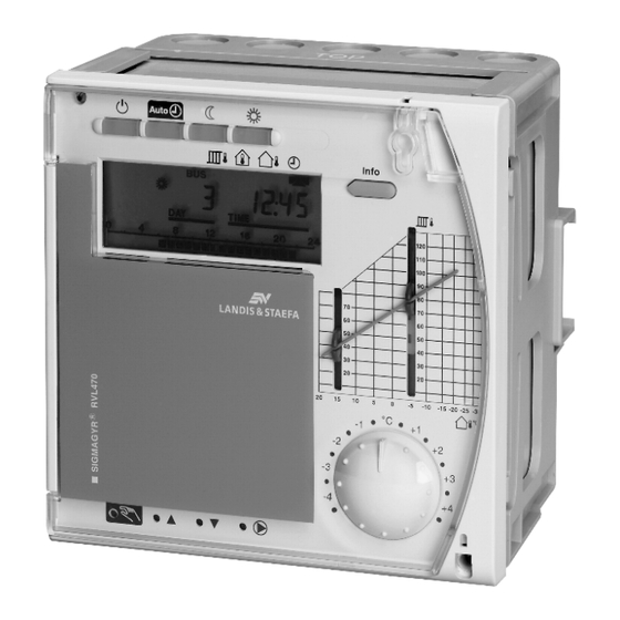
Heating Controller
for use with a partner unit
• Multifunctional heating controller for use in residential and non-residential
buildings; suitable for weather-dependent flow temperature control of heating
zones with or without room temperature compensation
• For exclusive use on the bus together with an RVL47... heatinmg controller as
a partner unit
• 1 programmed plant type: three-position control of the mixing valve in a heat-
ing zone
• Analog or digital setting of the heating curve, analog room temperature read-
justment, operating line principle for all other parameters
• Operating voltage AC 230 V, CE conformity
• Types of buildings:
– Multi-family houses
– Single-family houses
– Smaller non-residential buildings
• Types of plants:
– Combined plants consisting of several heating zones and heat generation
• Types of heating systems:
– Radiator, convector, underfloor and ceiling heating systems, radiating panels
Weather-dependent flow temperature control through control of the mixing valve in a
heating zone in combined plants.
Automatic mode
Automatic changeover from normal to reduced temperature, and vice versa,
according to the seven-day program, automatic changeover to holiday mode,
demand-dependent control of heating system (ECO function)
Setback mode
Continuous heating to the reduced temperature, with ECO function
Comfort mode
Continuous heating to the normal temperature, no ECO function
Standby
Frost protection is ensured in all operating modes.
The controller can be switched to manual operation.
2
527
Series B
RVL469
CE1N2527E / 04.03.1999
1/8
Advertisement
Table of Contents

Related Manuals for Siemens RVL469


Summary of Contents for Siemens RVL469
- Page 1 (ECO function) Setback mode Continuous heating to the reduced temperature, with ECO function Comfort mode Continuous heating to the normal temperature, no ECO function Standby Series B RVL469 CE1N2527E / 04.03.1999...
- Page 2 – RVL471 (data sheet CE1N2524E) – RVL472 (data sheet CE1N2526E) – RVL47 (data sheet CE1N2523E) • Flow and return temperature: all sensors with LG-Ni 1000 Ω at 0 °C, for example: Suitable sensors and room units – Clamp-on temperature sensor QAD22 –...
- Page 3 – Flow temperature: with one or two (averaging) sensors Temperature acquisition – Outside temperature: with Ni or NTC sensor; the RVL469 identifies the type of sensor used; with interlinked controllers, it is also possible to define the source of the outside temperature –...
- Page 4 Communication To provide this function, connection of the RVL469 to ist partner unit via the data bus is mandatory. Each RVL469 requires one partner unit. Communication with other units also takes place via the data bus and facilitates: – Signalling of heat demand to the heat source –...
- Page 5 Notes The wires of the measuring circuits carry extra low voltage, those to the actuator and the Engineering pump carry AC 24…230 V. The local electrical regulations must be complied with. Sensor cables should not be run parallel to mains carrying cables for loads such as ac- tuator, pump, etc.
- Page 6 20 m 80 m 120 m 25 m 50 m 12 h min. 1.1 kg D1 D2 Heating circuit pump Controller RVL469 Remote control operating mode Remote control flow temperature setpoint Actuator heating circuit Siemens Building Technologies Landis & Staefa Division...
- Page 7 Dimensions Dimensions in mm Siemens Building Technologies Landis & Staefa Division 26 26 26 26 (42,5) max. 3 -0/+1 CE1N2527E / 04.03.1999...
- Page 8 1999 Siemens Building Technologies Ltd. CE1N2527E / 04.03.1999 Siemens Building Technologies Landis & Staefa Division...
Need help?
Do you have a question about the RVL469 and is the answer not in the manual?
Questions and answers