
Related Manuals for Hughes HN9800

Summary of Contents for Hughes HN9800
- Page 1 HN System HN9800 Satellite Modem User Guide 1039708-0001 Revision A April 10, 2013 11717 Exploration Lane, Germantown, MD 20876 Phone (301) 428-5500 Fax (301) 428-1868/2830...
- Page 2 The information in this document is subject to change without notice. Hughes Network Systems, LLC makes no warranty of any kind with regard to this material, including, but not limited to, the implied warranties of merchantability and fitness for a particular purpose.
-
Page 3: Table Of Contents
Contents Understanding safety alert messages....5 Messages concerning personal injury ..... . 5 Messages concerning property damage . - Page 4 Chapter 3 LEDs .........25 LAN port LEDs .
-
Page 5: Understanding Safety Alert Messages
Understanding safety alert messages Safety alert messages call attention to potential safety hazards and tell you how to avoid them. These messages are identified by the signal words DANGER, WARNING, CAUTION, or NOTICE, as illustrated below. To avoid possible property damage, personal injury, or in some cases possible death, read and comply with all safety alert messages. -
Page 6: Safety Symbols
Safety symbols The generic safety alert symbol calls attention to a potential personal injury hazard. It appears next to the DANGER, WARNING, and CAUTION signal words as part of the signal word label. Other symbols may appear next to DANGER, WARNING, or CAUTION to indicate a specific type of hazard (for example, fire or electric shock). -
Page 7: Overview
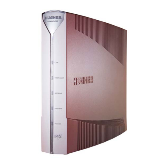
LAN. Figure 1 shows the front of the HN9800 satellite modem. After your HN9800 satellite modem has been installed, you can use your computer’s web browser to access the Internet or an intranet. The HN9800 supports local area networks (LANs) to extend Internet connectivity to multiple computers. This requires an Ethernet cable or a wireless or a wired connection to the LAN and proper configuration of the computer's operating system network properties. -
Page 8: Operating Environment
Operating position Operate the HN9800 only in a vertical position, that is, resting on its built-in base as shown in Figure 1 on page 7. Computer requirements... - Page 9 Click Chat with Us! 4. Call a Customer Care representative. If none of these options helps you, call Hughes Customer Care at 1 (866) 347-3292. For modems purchased from a value-added reseller (VAR) in the United States or Canada: If you purchased this product from a Hughes VAR, do not contact Hughes.
- Page 10 Chapter 1 • Overview 1039708-0001 Revision A...
-
Page 11: System Control Center
Chapter 2 System Control Center The System Control Center is a set of screens and links you can use to monitor your broadband service and troubleshoot the satellite modem in the event of a problem. The System Control Center provides access to system status, configuration information, and online documentation. -
Page 12: System Control Center Home Page
System Control Center home page The System Control Center home page as shown in Figure 2 contains numerous links to satellite modem features and important information regarding operation of the satellite modem. Figure 2: System Control Center home page The button links at the top of the page (Figure 3) appear on all System Control Center screens. -
Page 13: Common Features On System Control Center Screens
- Through this link you can find general operating instructions for the Getting Started HN9800 modem, recommended settings for your browser and TCP/IP, answers to frequently asked questions, and troubleshooting information. - Opens the Help page, which includes a variety of topics such as View Help Topics recommended browser and TCP/IP settings. -
Page 14: System Status Button
System Status button link is also a status indicator, as explained in Table 2. The other three button links are links only; they are not indicators. Figure 5: System Control Center button links The table below identifies the destination for each button link. Table 1: Button links on System Control Center screens Button Destination... -
Page 15: Ipsec Icon
detailed status information, click the System Status button to open the System Status page. Table 2: Status button colors Button color Meaning Green The satellite modem is operating normally. (OK System Status button appears beneath the page 14.) A problem has been detected. Yellow Performance is temporarily impaired because: •... -
Page 16: Links In The Left Panel
two points. An IPSec tunnel is up when it has been established between two peers and is capable of carrying traffic. If it cannot carry traffic it is down. When IPSec is enabled (IPSec icon present), the modem attempts to establish all configured tunnels. -
Page 17: Parameters And Values
Parameters and values Several of the System Control Center screens list status and operational parameters and their current values in a tabular format. For example, the following illustration shows the Reception Information page. The left column list the parameters, and the right column shows the current value of the parameter listed in the left column. -
Page 18: Features A Customer May Not See
Features a customer may not see A customer may see descriptions of certain features in the satellite modem user guide that do not appear on their System Control Center screens. This is because some features may be enabled or disabled by the NOC depending on the customer’s service plan or customer-specific requirements. -
Page 19: Reception Information Page
Level of encoding the modem can accept based on the current signal quality. Lower Modcod numbers are used if signal impairments such as rain are present. Adaptive coding and modulation (Modcod) is a Hughes-developed technique that maximizes over-the-air bandwidth utilization. Chapter 2 • System Control Center... -
Page 20: Examining Receive Status
Examining receive status You can check the Receive Status parameter to find out if the receive data path is operational or if there is a problem. Normal receive status is indicated by the message Receiver operational. ( RxCode 5 The following illustration shows how you can view a list of all RxCodes or see an explanation of the currently displayed RxCode. -
Page 21: Transmission Information Page
Transmission Information page The Transmission Information page shown in Figure 13 displays information about data transmissions from the satellite modem. Figure 13: Transmission Information page The following table gives an explanation of the parameters on the Transmission Information page. Table 4: Transmission Information page parameters Parameter Explanation Transmit Status... -
Page 22: System Information Page
The following two illustrations show how you can view a list of all TxCodes or see an explanation of the currently displayed TxCode. Each TxCode—except TxCode 8—indicates a specific problem in the transmission path. Figure 14: Finding additional Transmit Status information System Information page The System Information page shown in Figure 15 provides system information for the satellite modem such as Site ID and the release number of the modem’s operational... -
Page 23: Help Page
Help page The System Control Center Help page (Figure 16) contains information to help the user get started in using the satellite modem, find contact information for assistance, and other helpful information. To display the Help page: • Click View Help Topics on the System Control Center home page. - Page 24 Chapter 2 • System Control Center 1039708-0001 Revision A...
-
Page 25: Leds
(on, off, blinking, or flashing) the LEDs indicate the modem's operating status. The front panel LEDs are all blue when lit. Figure 17: Front panel LEDS on the HN9800 Table 5 explains what the modem status is when the LEDs are on, off, or blinking. On means the LED is continuously lit. - Page 26 intermittently turns off briefly. Flashing means the LED alternates between on and off for periods of ½ sec to 1 sec. Table 5: Front panel LED indications Appearance Status Satellite modem is connected to a computer network card or Ethernet device Blinking Transmitting and/or receiving data...
-
Page 27: Lan Port Leds
LAN port LEDs Green and orange LEDs on the LAN (Ethernet) port on the modem's rear panel indicate link status and speed, as explained in Figure 18. Figure 18: LAN port LEDs Chapter 3 • LEDs 1039708-0001 Revision A... - Page 28 Chapter 3 • LEDs 1039708-0001 Revision A...
-
Page 29: Standards Compliance
Appendix A Standards compliance The HN9800 satellite modem has been certified to comply with the standards listed in Table 6. Additional information follows the table. Table 6: HN9800 standards compliance Category Standard Safety UL60950-1 for the USA, International CAN/CSA-C22.2 No. 60950-1 for Canada... -
Page 30: Electromagnetic Interference (Emi)
FCC Part 15 This section applies to the HN9800 satellite modem. Standards to which conformity is declared: FCC Part 15 The modem complies with Part 15 of the FCC Rules. Operation is subject to the... -
Page 31: Acronyms And Abbreviations
Acronyms and abbreviations CAN – Canada CSA – Canadian Standards Association DHCP – Dynamic host configuration protocol EMI – Electromagnetic Interference EU – European Union IPSec – Internet Protocol security LAN – Local area network LLC – Limited Liability Company Networking requirements VAR –... - Page 32 • Acronyms and abbreviations 1039708-0001 Revision A...
-
Page 33: Index
Index Advanced Pages 16 Network requirements 8 Button links on System Control Center pages 13 Operating 8 Operating environment 8 Operating position 8 Canadian safety standards 29 Color of System Status button 14 Computer requirements 8 Parameters on System Control Center screens 17 Contact information 8 CSA Canadian Standards Association 30 Receive status 20... - Page 34 • Index 1039708-0001 Revision A...
Need help?
Do you have a question about the HN9800 and is the answer not in the manual?
Questions and answers