Vega VEGAPULS 63 Operating Instructions Manual
Radar sensor for continuous level measurement of aggressive liquids or with hygienic requirements 20 ma/hart - four-wire
Hide thumbs
Also See for VEGAPULS 63:
- Operating instructions manual (104 pages) ,
- Quick setup manual (20 pages) ,
- Safety manual (16 pages)
Table of Contents
Advertisement
Quick Links
Advertisement
Table of Contents

Related Manuals for Vega VEGAPULS 63


Summary of Contents for Vega VEGAPULS 63
-
Page 1: Operating Instructions
Operating Instructions VEGAPULS 63 4 … 20 mA/HART - four-wire Radar... -
Page 2: Table Of Contents
Menu schematic ..... . . 37 Saving the parameter adjustment data ..39 VEGAPULS 63 • 4 … 20 mA/HART - four-wire... - Page 3 "Product description". Instructions manuals for accessories and replacement parts Tip: To ensure reliable setup and operation of your VEGAPULS 63, we offer accessories and replacement parts. The associated documents are: 27720 - VEGADIS 61 30176 - Electronics module VEGAPULS series 60 31088 - Flanges according to DIN-EN-ASME-JIS VEGAPULS 63 •...
-
Page 4: About This Document
The dot set in front indicates a list with no implied sequence. à Action This arrow indicates a single action. Sequence Numbers set in front indicate successive steps in a procedure. VEGAPULS 63 • 4 … 20 mA/HART - four-wire... -
Page 5: For Your Safety
During work on and with the device the required personal protection equipment must always be worn. 2.2 Appropriate use VEGAPULS 63 is a sensor for continuous level measurement. You can find detailed information on the application range in chapter "Product description". -
Page 6: Safety Approval Markings And Safety Tips
VEGA instruments are generally upward and downward compatible. Sensor software for DTM VEGAPULS 63 HART, PA or FF R & TTE-Richtlinie 1999/5/EC: Not with version with increased sensitivity. VEGAPULS 63 • 4 … 20 mA/HART - four-wire... -
Page 7: Fcc/Ic Conformity (Only For Usa/Canada)
Modifications not expressly approved by VEGA will lead to expiry of the operating licence according to FCC/IC. VEGAPULS 63 is in conformity with part 15 of the FCC directives and fulfills the RSS-210 regulations. Note the corresponding regulations for operation:... -
Page 8: Environmental Instructions
DIN EN ISO 14001. Please help us fulfil this obligation by observing the environ- mental instructions in this manual: Chapter "Packaging, transport and storage" Chapter "Disposal" VEGAPULS 63 • 4 … 20 mA/HART - four-wire... -
Page 9: Product Description
3 Product description 3 Product description 3.1 Configuration The VEGAPULS 63 radar sensor is available in two electronics Versions versions: Standard electronics type PS60KV Electronics with increased sensitivity type PS60KE The respective version can be determined by means of the type label on the electronics. -
Page 10: Principle Of Operation
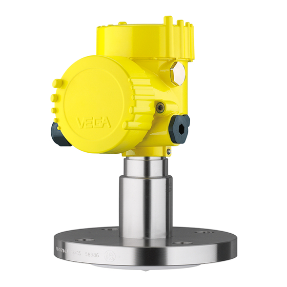
3 Product description Fig. 1: VEGAPULS 63 - flange version with Alu double chamber housing Housing cover with integrated PLICSCOM (optional) Housing with electronics Process fitting with encapsulated antenna system 3.2 Principle of operation VEGAPULS 63 is a radar sensor in K-band technology Area of application (emitting frequency approx. -
Page 11: Operation
Up to the time of installation, the packages must be left closed Storage and stored according to the orientation and storage markings on the outside. VEGAPULS 63 • 4 … 20 mA/HART - four-wire... - Page 12 Protected against solar radiation Avoiding mechanical shock and vibration Storage and transport temperature see "Supplement - Storage and transport temperature Technical data - Ambient conditions" Relative humidity 20 … 85 % VEGAPULS 63 • 4 … 20 mA/HART - four-wire...
-
Page 13: Mounting
The reference plane for the measuring range of the sensors is Measuring range the lower edge of the flange. Information: If the medium reaches the antenna, buildup can form on it and cause faulty measurements later on. VEGAPULS 63 • 4 … 20 mA/HART - four-wire... -
Page 14: Mounting Instructions
flange screws on PTFE coated flanges. Tighten the screws moderately with the torque stated in the technical data. When mounting VEGAPULS 63, keep a distance of at least Mounting position 200 mm (7.874 in) to the vessel wall. If the sensor is installed in the center of dished or round vessel tops, multiple echoes can arise. - Page 15 Fig. 5: Vessel with conical bottom Do not mount the instruments in or above the filling stream. Inflowing medium Make sure that you detect the product surface, not the inflowing product. VEGAPULS 63 • 4 … 20 mA/HART - four-wire...
- Page 16 Mounting on socket If the reflective properties of the medium are good, you can mount VEGAPULS 63 on a socket piece. You will find recommended values for socket heights in the following illustration. The socket end should be smooth and burr-free, if possible also rounded.
- Page 17 If there are agitators in the vessel, a false echo storage should Agitators be carried out with the agitators in motion. This ensures that the interfering reflections from the agitators are saved with the blades in different positions. VEGAPULS 63 • 4 … 20 mA/HART - four-wire...
- Page 18 Make sure you provide the necessary upper vent hole in the surge pipe. The hole must be aligned so that it and the polarisation marking on the sensor are in the same plane (see illustration: "Pipe antenna system in a tank"). VEGAPULS 63 • 4 … 20 mA/HART - four-wire...
- Page 19 Align the sensor in such a way that the polarisation marking on the process fitting is in the same plane as the tube holes or the tube connection openings (see illustration: "VEGAPULS in a bypass tube"). VEGAPULS 63 • 4 … 20 mA/HART - four-wire...
- Page 20 4 Mounting 100% Fig. 12: VEGAPULS 63 in a bypass tube. The polarisation marking on the process fitting must be in one plane with the tube holes or the tube connection openings. Marking of the polarisation direction When the sensor is mounted on a bypass tube, the distance from VEGAPULS 63 to the upper tube connection should be approx.
-
Page 21: Connecting To Power Supply
The 4 … 20 mA current output is connected with standard two- wire cable without screen. If electromagnetic interference is expected which is above the test values of EN 61326 for industrial areas, screened cable should be used. VEGAPULS 63 • 4 … 20 mA/HART - four-wire... -
Page 22: Connection Procedure
1 cm (0.4 in) insulation from the ends of the individual wires 5 Insert the cable through the cable gland into the sensor 6 Lift the opening levers of the terminals with a screwdriver (see following illustration) VEGAPULS 63 • 4 … 20 mA/HART - four-wire... -
Page 23: Wiring Plan, Double Chamber Housing
12 Screw the housing cover on The electrical connection is finished. 5.3 Wiring plan, double chamber housing The following illustrations apply to the non-Ex as well as to the Ex-d version. VEGAPULS 63 • 4 … 20 mA/HART - four-wire... - Page 24 I ² C 5 6 7 8 Fig. 15: Electronics compartment, double chamber housing Plug connector for VEGACONNECT (I²C interface) Internal connection cable to the connection compartment Terminals for VEGADIS 61 VEGAPULS 63 • 4 … 20 mA/HART - four-wire...
-
Page 25: Switch On Phase
Fig. 17: Wiring plan, double chamber housing Voltage supply Signal output 5.4 Switch on phase After connecting VEGAPULS 63 to power supply or after a Switch on phase voltage recurrence, the instrument carries out a self-check for approx. 30 seconds:... - Page 26 Output signal jumps briefly (approx. 10 seconds) to the set fault current Then the corresponding current is outputted to the cable (the value corresponds to the actual level as well as the settings already carried out, e.g. factory setting). VEGAPULS 63 • 4 … 20 mA/HART - four-wire...
-
Page 27: Set Up With The Indicating And Adjustment Module Plicscom
4 Screw housing cover with inspection window tightly back Removal is carried out in reverse order. The indicating and adjustment module is powered by the sensor, an additional connection is not necessary. VEGAPULS 63 • 4 … 20 mA/HART - four-wire... - Page 28 Fig. 18: Installation of the indicating and adjustment module Note: If you intend to retrofit the instrument with an indicating and adjustment module for continuous measured value indication, a higher cover with an inspection glass is required. VEGAPULS 63 • 4 … 20 mA/HART - four-wire...
-
Page 29: Adjustment System
Approx. 10 minutes after the last pressing of a key, an automatic reset to measured value indication is triggered. Any values not confirmed with [OK] will not be saved. VEGAPULS 63 • 4 … 20 mA/HART - four-wire... -
Page 30: Setup Procedure
PACTware or DTM. HART mode Standard Address 0 As VEGAPULS 63 is a distance measuring instrument, the Parameter adjustment distance from the sensor to the product surface is measured. To have the real product level displayed, an allocation of the measured distance to the percentage height must be made. - Page 31 Keep in mind that the max. level must lie below the dead band. 3 Save the settings with [OK] and move to "Medium selection" with [->]. VEGAPULS 63 • 4 … 20 mA/HART - four-wire...
- Page 32 With "Liquids" these are "Storage tank", "Stilling tube", "Open vessel" or "Stirred vessel", with "Solid", "Silo" or "Bunker". Vessel form Storage tank Information: With VEGAPULS 63 with electronics version "Increased VEGAPULS 63 • 4 … 20 mA/HART - four-wire...
- Page 33 1 Move from the measured value display to the main menu by pushing [OK]. 2 Select the menu item "Service" with [->] and confirm with [OK]. Now the menu item "False signal suppression" is displayed. VEGAPULS 63 • 4 … 20 mA/HART - four-wire...
- Page 34 The menu item "Extended setting" offers the possibility to Extended setting/Quick optimise VEGAPULS 63 for applications in which the level level change changes very quickly. For this reason, select the function "Quick level change > 1 m/min.".
- Page 35 The values of the following menu items are not reset to the reset values (see chart) with "Reset": Menu item Reset value no reset Lighting no reset Language no reset Sensor-specific basic adjustment. VEGAPULS 63 • 4 … 20 mA/HART - four-wire...
- Page 36 "Indicating and adjustment module". Special parameters are parameters which are set customer-specifically on the service level with the adjustment software PACTware. VEGAPULS 63 • 4 … 20 mA/HART - four-wire...
-
Page 37: Menu Schematic
Displayed value Display unit Scaling Lighting 0 % = 0.0 l Scaled Volume ▼ Switched off ▼ 100 % = 100.0 l ▼ Diagnostics Basic adjustment Display ▶ Diagnostics Service Info VEGAPULS 63 • 4 … 20 mA/HART - four-wire... - Page 38 Basic adjustment Display Diagnostics Service ▶ Info Sensor type Date of manufacture Last change using PC Sensor characteristics 4. August 2008 Software version Display now? Serial number 3.50 4. August 2008 12345678 VEGAPULS 63 • 4 … 20 mA/HART - four-wire...
-
Page 39: Saving The Parameter Adjustment Data
They are hence available for multiple use or service purposes. If VEGAPULS 63 is equipped with an indicating and adjust- ment module, the most important data can be read out of the sensor into indicating and adjustment module. The procedure is described in the operating instructions manual "Indicating... -
Page 40: Setup With Pactware And Other Adjustment Programs
External connection via I²C interface TWIST Fig. 21: Connection via I²C connection cable I²C bus (com.) interface on the sensor I²C connection cable of VEGACONNECT VEGACONNECT USB cable to the PC VEGAPULS 63 • 4 … 20 mA/HART - four-wire... -
Page 41: Parameter Adjustment With Pactware
With power supply units with integrated HART resistance (internal resistance approx. 250 Ω), an additional external resistance is not necessary. This applies, e. g. to the VEGA instruments VEGATRENN 149A, VEGADIS 371, VEGAMET 381). Also usual Ex separators are most of the time equipped with a sufficient current limitation resistor. -
Page 42: Parameter Adjustment With Ams™ And Pdm
All currently available VEGA DTMs are provided in the DTM Collection on CD and can be obtained from the responsible VEGA agency for a token fee. This CD includes also the up-to- date PACTware version. The basic version of this DTM Collection incl. -
Page 43: Maintenance And Fault Rectification
However, should these measures not be successful, call the 24 hour service hotline VEGA service hotline in urgent cases under the phone no. +49 1805 858550. The hotline is available to you 7 days a week round-the-clock. - Page 44 à Exchange instrument or return instrument for repair Depending on the failure reason and measures taken, the Reaction after fault rec- steps described in chapter "Set up" must be carried out again, tification if necessary. VEGAPULS 63 • 4 … 20 mA/HART - four-wire...
-
Page 45: Exchanging The Electronics Module
Please ask the agency serving you for the address of your return shipment. You can find the respective agency on our website www.vega.com under: "Company - VEGA world- wide" VEGAPULS 63 • 4 … 20 mA/HART - four-wire... -
Page 46: Dismounting Steps
Materials: see chapter "Technical data" If you have no possibility to dispose of the old instrument professionally, please contact us concerning return and disposal. VEGAPULS 63 • 4 … 20 mA/HART - four-wire... -
Page 47: Supplement
22 mA < 500 Ω Load Integration time (63 % of the input 0 … 999 s, adjustable variable) Fulfilled NAMUR recommendations NE 43 With inductive load ohmic share min. 25 Ω/mH. VEGAPULS 63 • 4 … 20 mA/HART - four-wire... - Page 48 Max. emitted HF power of the antenna system - Pulse peak power < 2 mW - Pulse duration < 2 ns Time to output the correct level (with max. 10 % deviation) after a sudden level change. VEGAPULS 63 • 4 … 20 mA/HART - four-wire...
- Page 49 0,5 m 20 m -3 mm -10 mm 0.394 in 0.118 in 1.640 ft 65.62 ft - 0.118 in -0.394 in Fig. 23: Deviation VEGAPULS 63 Incl. non-linearity, hysteresis and non-repeatability. VEGAPULS 63 • 4 … 20 mA/HART - four-wire...
- Page 50 3.280 ft 65.62 ft - 0.590 in - 1.180 in Fig. 24: Deviation VEGAPULS 63 with increased sensitivity in mm, measuring range in m Influence of the ambient temperature to the sensor electronics Average temperature coefficient of the 0.03 %/10 K zero signal (temperature error) Influence of the superimposed gas and pressure to the accuracy...
- Page 51 -25 … +130 °C (-13 … +266 °F) lated, process seal FKM (Viton) - TFM-PTFE hygienically encapsu- -40 … +130 °C (-40 … +266 °F) lated, process seal EPDM Not suitable for SIL applications. VEGAPULS 63 • 4 … 20 mA/HART - four-wire...
- Page 52 20 … 72 V DC, 20 … 253 V AC, 50/60 Hz Max. power consumption 4 VA; 2.1 W Electrical protective measures IP 66/IP 67 Protection Tested according to the regulations of German Lloyd, GL directive 2. VEGAPULS 63 • 4 … 20 mA/HART - four-wire...
- Page 53 Depending on the version, instruments with approvals can have different technical data. For these instruments, the corresponding approval documents have to be taken into account. These are part of the delivery or can be downloaded via the serial number search under www.vega.com. VEGAPULS 63 • 4 … 20 mA/HART - four-wire...
-
Page 54: Dimensions
10.2 Dimensions Housing / ") ø 84mm ") M12x M20x1,5/ ½ NPT Fig. 25: Aluminium double chamber housing (with integrated PLICSCOM the height of the housing increases by 9 mm/0.35 in) VEGAPULS 63 • 4 … 20 mA/HART - four-wire... - Page 55 " " " Fig. 26: VEGAPULS 63 - flange version DN 50 and 2" DN 80 … DN 150 and 3" … 6" Diameter and number of holes in the flange VEGAPULS 63 • 4 … 20 mA/HART - four-wire...
- Page 56 ø 50mm ") ") ø 90mm ") ø 78mm ø 90mm ") ") Fig. 27: VEGAPULS 63 - hygienic fitting 1 NeumoBiocontrol Tuchenhagen Varivent DN 25 Hygienic fitting LA Hygienic fitting LB VEGAPULS 63 • 4 … 20 mA/HART - four-wire...
- Page 57 ø 106 DN 100 / 4” ø 119 Fig. 28: VEGAPULS 63 - hygienic fitting 2 Tri-Clamp DN 50, 2", 2½", DN 65, 3" Tri-Clamp DN 80, 3½", DN 100, 4" VEGAPULS 63 • 4 … 20 mA/HART - four-wire...
- Page 58 Fig. 29: VEGAPULS 63 - hygienic fitting 3 Bolting DIN 11851, DN 50, 2" and 3" Bolting DIN 11851, DN 80, 4" Bolting DIN 11864-2, DN 50 Bolting DIN 11864-2, DN 80 VEGAPULS 63 • 4 … 20 mA/HART - four-wire...
- Page 59 10 Supplement VEGAPULS 63 - hygienic fitting 4 ø 84mm ") ø 114mm ") Fig. 30: VEGAPULS 63 - hygienic fitting 4 SMS DN 51 SMS DN 76 VEGAPULS 63 • 4 … 20 mA/HART - four-wire...
-
Page 60: Industrial Property Rights
миру правами на интеллектуальную собственность. Дальнейшую информацию смотрите на сайте http://www. vega.com. VEGA系列产品在全球享有知识产权保护。 进一步信息请参见网站<http://www.vega.com>。 10.4 Trademark All brands used as well as trade and company names are property of their lawful proprietor/originator. VEGAPULS 63 • 4 … 20 mA/HART - four-wire... - Page 61 10 Supplement VEGAPULS 63 • 4 … 20 mA/HART - four-wire...
- Page 62 10 Supplement VEGAPULS 63 • 4 … 20 mA/HART - four-wire...
- Page 63 10 Supplement VEGAPULS 63 • 4 … 20 mA/HART - four-wire...
- Page 64 All statements concerning scope of delivery, application, practical use and operating conditions of the sensors and processing systems correspond to the information avail- able at the time of printing. © VEGA Grieshaber KG, Schiltach/Germany 2008 Subject to change without prior notice 28441-EN-080826...
Need help?
Do you have a question about the VEGAPULS 63 and is the answer not in the manual?
Questions and answers