Vega VEGAPULS 63 Operating Instructions Manual
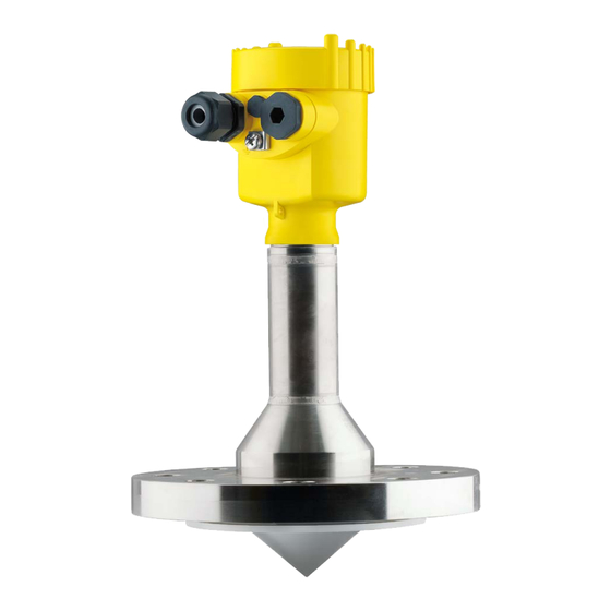
Radar sensor for continuous level
measurement of liquids
two-wire 4...20 ma/hart
Hide thumbs
Also See for VEGAPULS 63:
- Operating instructions manual (104 pages) ,
- Quick setup manual (20 pages) ,
- Safety manual (16 pages)

Subscribe to Our Youtube Channel
Related Manuals for Vega VEGAPULS 63


Summary of Contents for Vega VEGAPULS 63
- Page 1 Operating Instructions Radar sensor for continuous level measurement of liquids VEGAPULS 63 Two-wire 4 … 20 mA/HART Document ID: 36511...
-
Page 2: Table Of Contents
Saving the parameterisation data ................... 59 Setup with PACTware ......................60 Connect the PC ......................60 Parameter adjustment ....................60 Saving the parameterisation data ................... 62 Set up with other systems ....................63 VEGAPULS 63 • Two-wire 4 … 20 mA/HART... - Page 3 11.4 Trademark ........................92 Safety instructions for Ex areas Take note of the Ex specific safety instructions for Ex applications. These instructions are attached as documents to each instrument with Ex approval and are part of the operating instructions. Editing status: 2018-11-23 VEGAPULS 63 • Two-wire 4 … 20 mA/HART...
-
Page 4: About This Document
Symbols used Document ID This symbol on the front page of this instruction refers to the Docu- ment ID. By entering the Document ID on www.vega.com you will reach the document download. Information, tip, note This symbol indicates helpful additional information. -
Page 5: For Your Safety
During work on and with the device, the required personal protective equipment must always be worn. Appropriate use VEGAPULS 63 is a sensor for continuous level measurement. You can find detailed information about the area of application in chapter "Product description". Operational reliability is ensured only if the instrument is properly used according to the specifications in the operating instructions manual as well as possible supplementary instructions. -
Page 6: Eu Conformity
It is hence approved for use inside closed vessels in countries of the Use is also approved in EFTA countries, provided the respective standards have been implemented. For operation inside of closed vessels, points a to f in annex E of EN 302372 must be fulfilled. VEGAPULS 63 • Two-wire 4 … 20 mA/HART... -
Page 7: Radio License For Usa
10°. • Open Air Environment: For operation outside of closed vessels, the following condition must be fulfilled: This device shall be installed and maintained to ensure a vertically downward orienta- tion of the transmit antenna's main beam. Furthermore, the use of VEGAPULS 63 • Two-wire 4 … 20 mA/HART... - Page 8 à garantir une orientation verticale vers le bas du faisceau principal de l’antenne émettrice. De plus, l’utilisation de tout mécanisme ne permettant pas l’orientation ver- ticale vers le bas du faisceau principal de l’émetteur est interdite VEGAPULS 63 • Two-wire 4 … 20 mA/HART...
-
Page 9: Installation And Operation In The Usa And Canada
Protection of the environment is one of our most important duties. That is why we have introduced an environment management system with the goal of continuously improving company environmental pro- tection. The environment management system is certified according to DIN EN ISO 14001. VEGAPULS 63 • Two-wire 4 … 20 mA/HART... - Page 10 2 For your safety Please help us fulfil this obligation by observing the environmental instructions in this manual: • Chapter "Packaging, transport and storage" • Chapter "Disposal" VEGAPULS 63 • Two-wire 4 … 20 mA/HART...
-
Page 11: Product Description
Go to "www.vega.com", "Search". Enter the serial number. Alternatively, you can access the data via your smartphone: • Download the VEGA Tools app from the "Apple App Store" or the "Google Play Store" • Scan the Data Matrix code on the type label of the instrument or •... -
Page 12: Principle Of Operation
The respective scope of delivery results from the order specification. Principle of operation Application area The VEGAPULS 63 is a radar sensor for continuous level measure- ment of aggressive liquids or with hygienic requirements. It is suitable for applications in storage tanks, process vessels, dosing vessels and reactors. -
Page 13: Packaging, Transport And Storage
PC/notebook with Bluetooth USB adapter (Windows operating system) You can find further information in the operating instructions "Display and adjustment module PLICSCOM" (Document-ID 36433). VEGACONNECT The interface adapter VEGACONNECT enables the connection of communication-capable instruments to the USB interface of a PC. For VEGAPULS 63 • Two-wire 4 … 20 mA/HART... - Page 14 PACTware with VEGA-DTM is required. You can find further information in the operating instructions "Interface adapter VEGACONNECT" (Document-ID 32628). VEGADIS 81 The VEGADIS 81 is an external display and adjustment unit for VEGA plics sensors. ® For sensors with double chamber housing the interface adapter "VEGADIS adapter"...
- Page 15 The supplementary electronics is a replacement part for 4 … 20 mA/ Supplementary electron- ics for double chamber HART sensors with double chamber housing. housing You can find further information in the operating instructions "Supple- mentary electronics for 4 … 20 mA/HART - two-wire" (Document-ID 42764). VEGAPULS 63 • Two-wire 4 … 20 mA/HART...
-
Page 16: Mounting
• Abrasion and mechanical influences You can find detailed information on the process conditions in chapter "Technical data" as well as on the type label. Suitability for the ambient The instrument is suitable for standard and extended ambient condi- conditions tions acc. to IEC/EN 61010-1. VEGAPULS 63 • Two-wire 4 … 20 mA/HART... -
Page 17: Mounting Instructions
Recommended torque, see chapter "Technical data", "Torques". Polarisation The emitted radar impulses of the radar sensor are electromagnetic waves. The polarisation is the direction of the electrical wave compo- nent. By turning the instrument in the connection flange or mounting boss, the polarisation can be used to reduce the effects of false echoes. The position of the polarisation is marked on the process fitting of the instrument. VEGAPULS 63 • Two-wire 4 … 20 mA/HART... - Page 18 4 Mounting Fig. 3: Position of the polarisation Marking hole Reference plane The measuring range of VEGAPULS 63 begins physically at the end of the antenna; the adjustment, however, begins at the reference plane. The reference plane is different depending on the sensor ver- sion. • Flange with encapsulated antenna system: The reference plane is the lower edge of the flange plating •...
- Page 19 In vessels with conical bottom it can be advantageous to mount the sensor in the centre of the vessel, as measurement is then possible down to the bottom. Fig. 6: Mounting of the radar sensor on vessels with conical bottom Inflowing medium Do not mount the instruments in or above the filling stream. Make sure that you detect the product surface, not the inflowing product. VEGAPULS 63 • Two-wire 4 … 20 mA/HART...
- Page 20 Fig. 8: Deviating socket dimensions The below charts specify the max. socket length h depending on the diameter d. Socket diameter d Socket length h 50 mm ≤ 100 mm 80 mm ≤ 300 mm 100 mm ≤ 400 mm VEGAPULS 63 • Two-wire 4 … 20 mA/HART...
- Page 21 They are included in the scope of delivery of the instrument and are intended for the flange screws. To seal effectively, the following requirements must be fulfilled: 1. Make sure the number of flange screws corresponds to the num- ber of flange holes 2. Use of disc springs as previously described Fig. 10: Use of disc springs Disc spring Sealing surface VEGAPULS 63 • Two-wire 4 … 20 mA/HART...
- Page 22 1. Dismount and clean the instrument, note chapters "Dismounting steps" and "Maintenance" 2. Loosen the PTFE washer manually and detach it Fig. 11: VEGAPULS 63 - Loosening the PTFE washer Note: Protect the thread against contamination 3. Remove the sealing and clean the sealing groove 4.
- Page 23 If foams are causing measurement errors, the biggest possible radar antennas, the electronics with increased sensitivity or low frequency radar sensors (C band) should be used. VEGAPULS 63 • Two-wire 4 … 20 mA/HART...
-
Page 24: Measurement Setup - Pipes
Under these prerequisites, the measurement of products with low dielectric values (ε value ≤ 1.6) is possible. Note the following illustrations and instructions for measurement in a surge pipe. Information: Measurement in a surge pipe is not recommended for extremely adhesive products. VEGAPULS 63 • Two-wire 4 … 20 mA/HART... - Page 25 4 Mounting Configuration surge pipe 100% Fig. 15: Configuration surge pipe VEGAPULS 63 Radar sensor Polarisation marking 3 Thread or flange on the instrument Vent hole Holes 6 Welding connection through U-profile Ball valve with complete opening Surge pipe end 9 Reflector sheet 10 Fastening of the surge pipe VEGAPULS 63 • Two-wire 4 … 20 mA/HART...
- Page 26 • A false signal suppression with the installed sensor is recom- mended but not mandatory • The measurement through a ball valve with unrestricted channel is possible VEGAPULS 63 • Two-wire 4 … 20 mA/HART...
- Page 27 • An extension via welding neck flanges or pipe collars is not recom- mended. Measurement in the An alternative to measurement in a surge pipe is measurement in a bypass tube bypass tube outside of the vessel. VEGAPULS 63 • Two-wire 4 … 20 mA/HART...
- Page 28 • A false signal suppression with the installed sensor is recom- mended but not mandatory • The measurement through a ball valve with unrestricted channel is possible VEGAPULS 63 • Two-wire 4 … 20 mA/HART...
- Page 29 Flanges are welded to the tube according to the orientation of the polarisation • Gap size with junctions ≤ 0.1 mm, for example, when using a ball valve or intermediate flanges with single pipe sections • The antenna diameter of the sensor should correspond to the inner diameter of the tube • Diameter should be constant over the complete length VEGAPULS 63 • Two-wire 4 … 20 mA/HART...
-
Page 30: Connecting To Power Supply
You have to remove these plugs before electrical connection. NPT thread In the case of instrument housings with self-sealing NPT threads, it is not possible to have the cable entries screwed in at the factory. The VEGAPULS 63 • Two-wire 4 … 20 mA/HART... -
Page 31: Connecting
3. Loosen compression nut of the cable gland and remove blind plug 4. Remove approx. 10 cm (4 in) of the cable mantle, strip approx. 1 cm (0.4 in) of insulation from the ends of the individual wires VEGAPULS 63 • Two-wire 4 … 20 mA/HART... -
Page 32: Wiring Plan, Single Chamber Housing
10. Reinsert the display and adjustment module, if one was installed 11. Screw the housing lid back on The electrical connection is finished. Wiring plan, single chamber housing The following illustration applies to the non-Ex as well as to the Ex-ia version. VEGAPULS 63 • Two-wire 4 … 20 mA/HART... -
Page 33: Wiring Plan, Double Chamber Housing
The following illustrations apply to the non-Ex as well as to the Ex-ia version. Electronics compartment 4...20mA 6 7 8 Fig. 20: Electronics compartment - double chamber housing Internal connection to the connection compartment For display and adjustment module or interface adapter VEGAPULS 63 • Two-wire 4 … 20 mA/HART... - Page 34 Ground terminal for connection of the cable screening Connection compart- ment - Radio module PLICSMOBILE 81 Status Send Fig. 22: Connection compartment - Radio module PLICSMOBILE 81 Voltage supply You can find detailed information for connection in the operating instructions "PLICSMOBILE". VEGAPULS 63 • Two-wire 4 … 20 mA/HART...
-
Page 35: Wiring Plan, Ex-D-Ia Double Chamber Housing
Ground terminal for connection of the cable screening Plug M12 x 1 for external display and adjustment unit Fig. 25: Top view of the plug connector Pin 1 Pin 2 Pin 3 Pin 4 VEGAPULS 63 • Two-wire 4 … 20 mA/HART... -
Page 36: Double Chamber Housing With Vegadis-Adapter
Pin 1 Pin 2 Pin 3 Pin 4 Contact pin Colour, connection ca- Terminal, electronics ble in the sensor module Pin 1 Brown Pin 2 White Pin 3 Blue Pin 4 Black VEGAPULS 63 • Two-wire 4 … 20 mA/HART... -
Page 37: Wiring Plan - Version Ip 66/Ip 68 (1 Bar)
As soon as a plausible measured value is found, the corresponding current is output to the signal cable. The value corresponds to the actual level as well as the settings already carried out, e.g. factory setting. VEGAPULS 63 • Two-wire 4 … 20 mA/HART... -
Page 38: Set Up With The Display And Adjustment Module
The display and adjustment module is powered by the sensor, an ad- ditional connection is not necessary. Fig. 29: Installing the display and adjustment module in the electronics compart- ment of the single chamber housing VEGAPULS 63 • Two-wire 4 … 20 mA/HART... -
Page 39: Adjustment System
Adjustment keys • Key functions [OK] key: – Move to the menu overview – Confirm selected menu – Edit parameter – Save value • [->] key: – Change measured value presentation – Select list entry VEGAPULS 63 • Two-wire 4 … 20 mA/HART... -
Page 40: Measured Value Indication - Selection Of National Language
Approx. 60 minutes after the last pressing of a key, an automatic reset to measured value indication is triggered. Any values not confirmed with [OK] will not be saved. Measured value indication - Selection of national language Measured value indica- With the [->] key you move between three different indication modes. tion VEGAPULS 63 • Two-wire 4 … 20 mA/HART... -
Page 41: Parameter Adjustment
In this operating instructions manual, the instrument-specific pa- rameters in the menu sections "Setup", "Diagnosis" and "Additional settings" are described. The general parameters in these menu sec- tions are described in the operating instructions manual "Display and adjustment module". VEGAPULS 63 • Two-wire 4 … 20 mA/HART... - Page 42 [OK] and jump to the next menu item with the [ESC] and the [->] key. Setup - Application In addition to the medium, also the application, i.e. the measuring site, can influence the measurement. VEGAPULS 63 • Two-wire 4 … 20 mA/HART...
- Page 43 – Short reaction time of the sensor not required Storage tank, circulation: • Setup: large-volumed, upright cylindrical, spherical • Medium speed: slow filling and emptying • Installations: small, laterally mounted or large, top mounted stirrer • Process/measurement conditions: – Relatively smooth product surface VEGAPULS 63 • Two-wire 4 … 20 mA/HART...
- Page 44 – Fast filling and emptying – Vessel is filled and emptied very often • Vessel: tight installation situation • Process/measurement conditions: – Condensation, buildup on the antenna – Foam generation • Properties, sensor: – Measurement speed optimized by virtually no averaging – Sporadic false echoes are suppressed VEGAPULS 63 • Two-wire 4 … 20 mA/HART...
- Page 45 – In outdoor facilities, water and snow on vessel top possible • Properties, sensor: – False signals outside the vessel are not taken into consideration – False signal suppression recommended Transportable plastic tank: • Vessel: VEGAPULS 63 • Two-wire 4 … 20 mA/HART...
- Page 46 – Stable and reliable measured values through frequent averag- – Insensitive in the close range Demonstration: • Adjustment for all applications which are not typically level meas- urement – Instrument demonstration – Object recognition/monitoring (additional settings required) VEGAPULS 63 • Two-wire 4 … 20 mA/HART...
- Page 47 To perform the adjustment, enter the distance with full and empty ves- sel, see the following example: VEGAPULS 63 • Two-wire 4 … 20 mA/HART...
- Page 48 2. Edit the percentage value with [OK] and set the cursor to the requested position with [->]. 3. Set the requested percentage value with [+] and save with [OK]. The cursor jumps now to the distance value. VEGAPULS 63 • Two-wire 4 … 20 mA/HART...
- Page 49 Depending on the sensor type, the factory setting is 0 s or 1 s. Setup - Current output, In the menu item "Current output mode" you determine the output mode characteristics and reaction of the current output in case of fault. VEGAPULS 63 • Two-wire 4 … 20 mA/HART...
- Page 50 When the PIN is active, adjustment via PACTware/DTM as well as other systems is also blocked. In delivery status, the PIN is "0000". Display - Language This menu item enables the setting of the requested national lan- guage. VEGAPULS 63 • Two-wire 4 … 20 mA/HART...
- Page 51 The respective min. and max. measured values of the electronics tem- temperature perature are saved in the sensor. These values as well as the current temperature value are displayed in the menu item "Peak values". VEGAPULS 63 • Two-wire 4 … 20 mA/HART...
- Page 52 Diagnosis - Curve indica- The "Echo curve" shows the signal strength of the echoes over the tion measuring range in dB. The signal strength enables an evaluation of the quality of the measurement. VEGAPULS 63 • Two-wire 4 … 20 mA/HART...
- Page 53 Instrument units the temperature unit. Additional settings - False The following circumstances cause interfering reflections and can signal suppression influence the measurement: • High mounting sockets • Vessel internals such as struts • Agitators • Buildup or welded joints on vessel walls VEGAPULS 63 • Two-wire 4 … 20 mA/HART...
- Page 54 "Extend", the distance to the product surface of the created false signal suppression is displayed. This value can now be changed and the false signal suppression can be extended to this range. Additional settings - Lin- A linearization is necessary for all vessels in which the vessel volume earization does not increase linearly with the level - e.g. a horizontal cylindri- VEGAPULS 63 • Two-wire 4 … 20 mA/HART...
- Page 55 Additional settings - Date/ In this menu item, the internal clock of the sensor is set. Time After a reset, certain parameter adjustments made by the user are Additional settings - Reset reset. VEGAPULS 63 • Two-wire 4 … 20 mA/HART...
- Page 56 Max. adjustment 0,000 m(d) Damping 0.0 s Current output mode 4 … 20 mA, < 3.6 mA Current output, min./max. Min. current 3.8 mA, max. current 20.5 mA Lock adjustment Released VEGAPULS 63 • Two-wire 4 … 20 mA/HART...
- Page 57 In the menu "Additional settings" the items "Distance unit, tem- perature unit and linearization" • The values of the user-programmable linearisation curve The 4 … 20 mA signal of the sensor is switched off. The sensor uses a constant current of 4 mA. The measuring signal is transmitted exclusively as a digital HART signal. VEGAPULS 63 • Two-wire 4 … 20 mA/HART...
- Page 58 PC. Instrument features In this menu item, the features of the sensor such as approval, pro- cess fitting, seal, measuring range, electronics, housing and others are displayed. VEGAPULS 63 • Two-wire 4 … 20 mA/HART...
-
Page 59: Saving The Parameterisation Data
In the display and adjust- If the instrument is equipped with a display and adjustment module, ment module the parameter adjustment data can be saved therein. The procedure is described in menu item "Copy device settings". VEGAPULS 63 • Two-wire 4 … 20 mA/HART... -
Page 60: Setup With Pactware
Note: With power supply units with integrated HART resistance (internal resistance approx. 250 Ω), an additional external resistance is not necessary. This applies, e.g. to the VEGA instruments VEGATRENN 149A, VEGAMET 381, VEGAMET 391. Common Ex separators are also usually equipped with a sufficient current limiting resistance. In such cases, the interface converter can be connected parallel to the 4 …... - Page 61 The standard version is available as a download under www.vega.com/downloads and "Software". The full version is avail- able on CD from the agency serving you. VEGAPULS 63 • Two-wire 4 … 20 mA/HART...
-
Page 62: Saving The Parameterisation Data
7 Setup with PACTware Saving the parameterisation data We recommend documenting or saving the parameterisation data via PACTware. That way the data are available for multiple use or service purposes. VEGAPULS 63 • Two-wire 4 … 20 mA/HART... -
Page 63: Set Up With Other Systems
This software is updated via the Internet and new EDDs are automatically accepted into the device catalogue of this software after they are released by the manufacturer. They can then be transferred to a Field Communicator. VEGAPULS 63 • Two-wire 4 … 20 mA/HART... -
Page 64: Diagnosis, Asset Management And Service
The data are read out via a PC with PACTware/DTM or the control system with EDD. The echo curves are stored with date and time and the corresponding Echo curve memory echo data. The memory is divided into two sections: VEGAPULS 63 • Two-wire 4 … 20 mA/HART... -
Page 65: Asset Management Function
(for example during simulation). This status message is inactive by default. It can be activated by the user via PACTware/DTM or EDD. Out of specification: The measured value is unreliable because an instrument specification was exceeded (e.g. electronics temperature). VEGAPULS 63 • Two-wire 4 … 20 mA/HART... - Page 66 Error in the calibration carried Exchanging the electronics Bit 8 of Byte 0 … 5 • out in the factory Send instrument for repair Error in the cali- • Error in the EEPROM bration VEGAPULS 63 • Two-wire 4 … 20 mA/HART...
- Page 67 Error in the non- active linearisation table • • M502 Hardware error EEPROM Exchanging the electronics Bit 2 of • Send instrument for repair Byte 14 … 24 Error in the diag- nostics memory VEGAPULS 63 • Two-wire 4 … 20 mA/HART...
-
Page 68: Rectify Faults
Operating voltage too low, load resist- Check, adapt if necessary ance too high • • Current signal greater than Sensor electronics defective Exchange the instrument or send it in 22 mA, less than 3.6 mA for repair VEGAPULS 63 • Two-wire 4 … 20 mA/HART... - Page 69 Amplitude or position of a false signal has Determine the reason for the changed changed (e.g. condensation, buildup); false signals, carry out false signal sup- false signal suppression no longer pression, e.g. with condensation time matches actual conditions VEGAPULS 63 • Two-wire 4 … 20 mA/HART...
- Page 70 9. Measured value Varying condensation or contamination on Carry out a false signal suppression or jumps sporadically to the antenna increase false signal suppression with 100 % during filling condensation/contamination in the close range by editing time VEGAPULS 63 • Two-wire 4 … 20 mA/HART...
- Page 71 24 hour service hotline Should these measures not be successful, please call in urgent cases the VEGA service hotline under the phone no. +49 1805 858550. The hotline is also available outside normal working hours, seven days a week around the clock.
-
Page 72: Exchanging The Electronics Module
Current instrument software as file You can find the current instrument software as well as detailed information on the procedure in the download area of our homepage: www.vega.com. Caution: Instruments with approvals can be bound to certain software versions. Therefore make sure that the approval is still effective after a software update is carried out. You can find detailed information in the download area at www.vega.com. VEGAPULS 63 • Two-wire 4 … 20 mA/HART... -
Page 73: How To Proceed If A Repair Is Necessary
You can find an instrument return form as well as detailed informa- tion about the procedure in the download area of our homepage: www.vega.com. By doing this you help us carry out the repair quickly and without having to call back for needed information. In case of repair, proceed as follows: •... -
Page 74: Dismount
Pass the instrument directly on to a specialised recycling company and do not use the municipal collecting points. If you have no way to dispose of the old instrument properly, please contact us concerning return and disposal. VEGAPULS 63 • Two-wire 4 … 20 mA/HART... -
Page 75: Supplement
Max. torque for NPT cable glands and Conduit tubes Ʋ Plastic housing 10 Nm (7.376 lbf ft) Ʋ Aluminium/Stainless steel housing 50 Nm (36.88 lbf ft) Glass with Aluminium and stainless steel precision casting housing VEGAPULS 63 • Two-wire 4 … 20 mA/HART... - Page 76 20.5 mA, 22 mA, < 3.6 mA Max. output current 22 mA Load See load resistance under Power supply Starting current ≤ 3.6 mA; ≤ 10 mA for 5 ms after switching on Damping (63 % of the input variable), 0 … 999 s adjustable VEGAPULS 63 • Two-wire 4 … 20 mA/HART...
- Page 77 Antenna edge Recommended measuring range Variables influencing measurement accuracy Specifications apply to the digital measured value Temperature drift - Digital output < 3 mm/10 K, max. 10 mm Specifications apply also to the current output Default values can be assigned individually. Already included in the meas. deviation VEGAPULS 63 • Two-wire 4 … 20 mA/HART...
- Page 78 Ʋ Clamp 2", 3" 18° Ʋ Clamp 3½", 4" 10° Time span after a sudden measuring distance change by max. 0.5 m in liquid applications, max 2 m with bulk solids applications, until the output signal has taken for the first time 90 % of the final value (IEC 61298-2). Outside the specified beam angle, the energy level of the radar signal is 50% (-3 dB) less. VEGAPULS 63 • Two-wire 4 … 20 mA/HART...
- Page 79 -1 … 10 bar (-100 … 1000 kPa/-14.5 … 145 psig) Flange PN 16 (300 lb), -1 … 16 bar (-100 … 1600 kPa/-14.5 … 232 psig) PN 40 (600 lb) EIRP: Equivalent Isotropic Radiated Power. VEGAPULS 63 • Two-wire 4 … 20 mA/HART...
- Page 80 M20 x 1.5; ½ NPT Connection cable Ʋ Wire cross-section 0.5 mm² (AWG 20) Ʋ Wire resistance < 0.036 Ω/m Ʋ Tensile strength < 1200 N (270 lbf) Ʋ Standard length 5 m (16.4 ft) VEGAPULS 63 • Two-wire 4 … 20 mA/HART...
- Page 81 Date format Day.Month.Year Time format 12 h/24 h Time zone, factory setting Max. rate deviation 10.5 min/year Additional output parameter - Electronics temperature Range -40 … +85 °C (-40 … +185 °F) Resolution < 0.1 K VEGAPULS 63 • Two-wire 4 … 20 mA/HART...
- Page 82 IP 66/IP 68 (0.2 bar) Type 6P IP 68 (1 bar) Double chamber IP 66/IP 68 (0.2 bar) Type 6P IP 68 (1 bar) Galvanic separation between electronics and metal housing parts VEGAPULS 63 • Two-wire 4 … 20 mA/HART...
-
Page 83: Dimensions
Instruments with approvals can have different technical specifications depending on the version. For that reason the associated approval documents of these instruments have to be carefully noted. They are part of the delivery or can be downloaded under www.vega.com, "Instrument search (serial number)" as well as in the download area. 11.2 Dimensions The following dimensional drawings represent only an extract of all possible versions. - Page 84 Fig. 56: Housing version with protection rating IP 66/IP 68 (1 bar), (with integrated display and adjustment module the housing is 18 mm/0.71 in higher) Aluminium - single chamber Aluminium - double chamber VEGAPULS 63 • Two-wire 4 … 20 mA/HART...
- Page 85 Fig. 58: Housing version with protection rating IP 66/IP 68 (1 bar), (with integrated display and adjustment module the housing is 18 mm/0.71 in higher) Stainless steel single chamber (electropolished) Stainless steel single chamber (precision casting) Stainless steel double chamber housing (precision casting) VEGAPULS 63 • Two-wire 4 … 20 mA/HART...
- Page 86 ø 44 mm (1.73") ø 75 mm (2.95") Fig. 59: VEGAPULS 63, flange version DN 50, DN 65, 2", 2½" from DN 80, 3" With stainless steel housings and Aluminium double chamber housings, this dimension is 98 mm (3.86") VEGAPULS 63 • Two-wire 4 … 20 mA/HART...
- Page 87 ø 44 mm ø 75 mm (1.73") (2.95") Fig. 60: VEGAPULS 63, flange version, low temperature DN 50, DN 65, 2", 2½" from DN 80, 3" With stainless steel housings and Aluminium double chamber housings, this dimension is 198 mm (7.80") VEGAPULS 63 • Two-wire 4 … 20 mA/HART...
- Page 88 ø 90 mm ø 78 mm (3.07") (3.54") Fig. 61: VEGAPULS 63, hygienic fitting 1 NeumoBiocontrol Tuchenhagen Varivent DN 25 Hygienic fitting LA Hygienic fitting LB With stainless steel housings and Aluminium double chamber housings, this dimension is 4 mm (0.157") less VEGAPULS 63 • Two-wire 4 … 20 mA/HART...
- Page 89 Clamp 2" (ø 64 mm), 2½" (ø 77.5 mm), 3" (ø 91 mm), (DIN 32676, ISO 2852) Clamp 3½" (ø 106 mm), 4" (ø 119 mm), (DIN 32676, ISO 2852) With stainless steel housings and Aluminium double chamber housings, this dimension is 4 mm (0.157") less VEGAPULS 63 • Two-wire 4 … 20 mA/HART...
- Page 90 Slotted nut DN 80, 3" (DIN 11851) Slotted nut DN 50 (DIN 11864-2) Slotted nut DN 80 (DIN 11864-2) With stainless steel housings and Aluminium double chamber housings, this dimension is 4 mm (0.157") less VEGAPULS 63 • Two-wire 4 … 20 mA/HART...
- Page 91 (2.56") ø 105 mm (4.13") ø 114 mm (4.49") Fig. 64: VEGAPULS 63, hygienic fitting 4 SMS DN 51 SMS DN 76 With stainless steel housings and Aluminium double chamber housings, this dimension is 4 mm (0.157") less VEGAPULS 63 • Two-wire 4 … 20 mA/HART...
-
Page 92: Industrial Property Rights
Les lignes de produits VEGA sont globalement protégées par des droits de propriété intellec- tuelle. Pour plus d'informations, on pourra se référer au site www.vega.com. VEGA lineas de productos están protegidas por los derechos en el campo de la propiedad indus- trial. Para mayor información revise la pagina web www.vega.com. - Page 93 HART 60 HART mode 57 Instrument units 53 Instrument version 58 Language 50 Linearisation curve 54 Lock adjustment 50 Main menu 41 Measured value memory 64 Measurement in a surge pipe 24 VEGAPULS 63 • Two-wire 4 … 20 mA/HART...
- Page 94 Notes VEGAPULS 63 • Two-wire 4 … 20 mA/HART...
- Page 95 Notes VEGAPULS 63 • Two-wire 4 … 20 mA/HART...
- Page 96 Subject to change without prior notice © VEGA Grieshaber KG, Schiltach/Germany 2018 VEGA Grieshaber KG Phone +49 7836 50-0 Am Hohenstein 113...
Need help?
Do you have a question about the VEGAPULS 63 and is the answer not in the manual?
Questions and answers