Vega VEGAPULS 63 Operating Instructions Manual
4 ... 20 ma/hart - four-wire
Hide thumbs
Also See for VEGAPULS 63:
- Operating instructions manual (104 pages) ,
- Quick setup manual (20 pages) ,
- Safety manual (16 pages)

Related Manuals for Vega VEGAPULS 63


Summary of Contents for Vega VEGAPULS 63
-
Page 1: Operating Instructions
Operating Instructions VEGAPULS 63 4 … 20 mA/HART - four-wire Document ID: 28441... -
Page 2: Table Of Contents
Saving the parameterisation data ................... 44 8 Maintenance and fault rectification 8.1 Maintenance ........................45 Rectify faults ........................45 Exchanging the electronics module ................46 Software update ......................46 How to proceed if a repair is necessary ................47 VEGAPULS 63 • 4 … 20 mA/HART - four-wire... - Page 3 10.4 Trademark ........................61 Safety instructions for Ex areas Take note of the Ex specific safety instructions for Ex applications. These instructions are attached as documents to each instrument with Ex approval and are part of the operating instructions manual. Editing status: 2017-01-11 VEGAPULS 63 • 4 … 20 mA/HART - four-wire...
-
Page 4: About This Document
This arrow indicates a single action. Sequence of actions Numbers set in front indicate successive steps in a procedure. Battery disposal This symbol indicates special information about the disposal of bat- teries and accumulators. VEGAPULS 63 • 4 … 20 mA/HART - four-wire... -
Page 5: For Your Safety
During work on and with the device the required personal protective equipment must always be worn. Appropriate use VEGAPULS 63 is a sensor for continuous level measurement. You can find detailed information about the area of application in chapter "Product description". Operational reliability is ensured only if the instrument is properly used according to the specifications in the operating instructions manual as well as possible supplementary instructions. -
Page 6: Eu Conformity
FCC/IC conformity (only for USA/Canada) VEGAPULS sensors with all antenna versions are FCC/IC approved. Modifications not expressly approved by VEGA will lead to expiry of the operating licence according to FCC/IC. VEGAPULS 63 is in conformity with part 15 of the FCC directives and fulfills the RSS-210 regulations. Note the corresponding regulations for operation: • This device may not cause interference, and •... - Page 7 2 For your safety tection. The environment management system is certified according to DIN EN ISO 14001. Please help us fulfil this obligation by observing the environmental instructions in this manual: • Chapter "Packaging, transport and storage" • Chapter "Disposal" VEGAPULS 63 • 4 … 20 mA/HART - four-wire...
-
Page 8: Product Description
3 Product description Product description 3.1 Configuration Versions The VEGAPULS 63 radar sensor is available in two electronics ver- sions: • Standard electronics type PS60KV • Electronics with increased sensitivity type PS60KE The respective version can be determined by means of the type label on the electronics. -
Page 9: Principle Of Operation
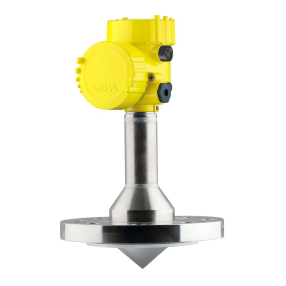
3 Product description Fig. 1: VEGAPULS 63 - flange version with Alu double chamber housing Housing cover with integrated PLICSCOM (optional) Housing with electronics Process fitting with encapsulated antenna system Type label The type label contains the most important data for identification and use of the instrument: • Instrument type •... -
Page 10: Packaging, Transport And Storage
Unless otherwise indicated, the packages must be stored only under the following conditions: • Not in the open • Dry and dust free • Not exposed to corrosive media • Protected against solar radiation • Avoiding mechanical shock and vibration VEGAPULS 63 • 4 … 20 mA/HART - four-wire... -
Page 11: Accessories And Replacement Parts
You can find further information in the operating instructions "Interface adapter VEGACONNECT" (Document-ID 32628). VEGADIS 81 The VEGADIS 81 is an external display and adjustment unit for VEGA plics sensors. ® For sensors with double chamber housing the interface adapter "DISADAPT"... -
Page 12: Mounting
The reference plane for the measuring range of the sensors is the lower edge of the flange. Information: If the medium reaches the antenna, buildup can form on it and cause faulty measurements later on. VEGAPULS 63 • 4 … 20 mA/HART - four-wire... -
Page 13: Mounting Instructions
The emitted radar impulses of VEGAPULS 63 are electromagnetic waves. The polarisation plane is the direction of the electrical share. Their position is marked on the instrument. Fig. 4: Position of the polarisation plane of VEGAPULS 63 Marking hole Suitability for the process... - Page 14 Installation position When mounting the VEGAPULS 63, keep a distance of at least 200 mm (7.874 in) to the vessel wall. If the sensor is installed in the center of dished or round vessel tops, multiple echoes can arise.
- Page 15 Mounting on socket If the reflective properties of the medium are good, you can mount VEGAPULS 63 on a socket piece. You will find recommended values for socket heights in the following illustration. The socket end should be smooth and burr-free, if possible also rounded. Then carry out a false signal suppression. VEGAPULS 63 • 4 … 20 mA/HART - four-wire...
- Page 16 If large vessel installations such as struts or supports cause false echoes, these can be attenuated through supplementary measures. Small, inclined sheet metal baffles above the installations scatter the radar signals and prevent direct interfering reflections. Fig. 10: Cover flat, large-area profiles with deflectors VEGAPULS 63 • 4 … 20 mA/HART - four-wire...
- Page 17 Surge pipe Make sure you provide the necessary upper vent hole in the surge pipe. The hole must be aligned so that it and the polarisation marking on the sensor are in the same plane (see illustration: "Pipe antenna system in a tank"). VEGAPULS 63 • 4 … 20 mA/HART - four-wire...
- Page 18 Vent hole max. ø 5 mm (0.2 in) If possible, the antenna diameter of the sensor should correspond to the inner diameter of the tube. With VEGAPULS 63 this is approx. 40 mm (1.575 in). The sensor can be used with tube diameters be- tween 40 …...
- Page 19 4 Mounting 100% Fig. 13: VEGAPULS 63 in a bypass tube. The polarisation marking on the process fitting must be in one plane with the tube holes or the tube connection openings. Marking of the polarisation direction When the sensor is mounted on a bypass tube, the distance from VEGAPULS 63 to the upper tube connection should be approx.
-
Page 20: Connecting To Power Supply
In Ex systems, the grounding is carried out according to the installa- tion regulations. With the Exd version, the minus side of the signal output is galvani- cally connected to ground via protective diodes. When connecting the instrument to a grounded PLC, equalising currents can flow in case VEGAPULS 63 • 4 … 20 mA/HART - four-wire... -
Page 21: Connection Procedure
11. Connect the lead cable for power supply in the same way accord- ing to the wiring plan, in addition connect the ground conductor to the inner ground terminal. 12. Screw the housing lid back on The electrical connection is finished. VEGAPULS 63 • 4 … 20 mA/HART - four-wire... -
Page 22: Wiring Plan, Double Chamber Housing
Fig. 16: Double chamber housing Housing cover, connection compartment Blind plug or plug M12 x 1 for VEGADIS 61 (optional) Housing cover, electronics compartment Filter element for air pressure compensation Cable gland VEGAPULS 63 • 4 … 20 mA/HART - four-wire... - Page 23 Ground terminal for connection of the ground conductor and screen Spring-loaded terminals for voltage supply Information: Keep in mind that the display and adjustment module must only be used in the electronics compartment. VEGAPULS 63 • 4 … 20 mA/HART - four-wire...
-
Page 24: Switch-On Phase
Fig. 19: Wiring plan - double chamber housing Voltage supply Signal output Switch-on phase Switch-on phase After connecting VEGAPULS 63 to power supply or after a voltage recurrence, the instrument carries out a self-check for approx. 30 seconds: • Internal check of the electronics •... -
Page 25: Set Up With The Display And Adjustment Module Plicscom
Disassembly is carried out in reverse order. The display and adjustment module is powered by the sensor, an ad- ditional connection is not necessary. Fig. 20: Insert display and adjustment module VEGAPULS 63 • 4 … 20 mA/HART - four-wire... -
Page 26: Adjustment System
– Jump to next higher menu Adjustment system The instrument is operated via the four keys of the display and adjust- ment module. The individual menu items are shown on the LC display. You can find the functions of the individual keys in the previous illustration. VEGAPULS 63 • 4 … 20 mA/HART - four-wire... -
Page 27: Setup Steps
At the same time, the operating range of the sensor is limited from maximum range to the requested range. 100% Fig. 22: Parameterisation example, Min./max. adjustment Min. level = max. measuring distance Max. level = min. measuring distance Reference plane VEGAPULS 63 • 4 … 20 mA/HART - four-wire... - Page 28 2. Enter the appropriate distance value in m (corresponding to the percentage value) for the full vessel. Keep in mind that the max. level must lie below the dead band. 3. Save the settings with [OK] and move to "Medium selection" with [->]. VEGAPULS 63 • 4 … 20 mA/HART - four-wire...
- Page 29 Basic adjustment - Damp- To suppress fluctuations in the measured value display, e. g. caused by an agitated product surface, a damping can be set. This time can be between 0 and 999 seconds. Keep in mind that the reaction time of VEGAPULS 63 • 4 … 20 mA/HART - four-wire...
- Page 30 Enter the requested parameters via the appropriate keys, save your settings and jump to the next menu item with the [->] key. Caution: Note the following if the VEGAPULS 63 with corresponding approval is used as part of an overfill protection system according to WHG (Water Resources Act): If a linearisation curve is selected, the measuring signal is no longer necessarily linear to the filling height. This must be considered by the...
- Page 31 Backlight In the default setting, the lightning is switched off. The respective min. and max. measured values are saved in the sen- Diagnosis - Peak value sor. The values are displayed in the menu item "Peak values". • Min. and max. distance in m(d) VEGAPULS 63 • 4 … 20 mA/HART - four-wire...
- Page 32 "X-Zoom": Zoom function for the meas. distance • "Y-Zoom": 1, 2, 5 and 10x signal magnification in "dB" • "Unzoom": Reset the presentation to the nominal measuring range without magnification In the menu item "Trend curve" the following are available: • "X-Zoom": Resolution – 1 minute – 1 hour – 1 day VEGAPULS 63 • 4 … 20 mA/HART - four-wire...
- Page 33 Service - Extended set- The menu item "Extended setting" offers the possibility to optimise ting VEGAPULS 63 for applications in which the level changes very quickly. To do this, select the function "Quick level change > 1 m/min.". Extended setting quick level change > 1 m/min.
- Page 34 Value of the current output in case of failure, e.g. if no valid measured value is delivered. This value is not underrun during operation. This value is not exceeded during operation. VEGAPULS 63 • 4 … 20 mA/HART - four-wire...
- Page 35 The values of the following menu items are not reset to the reset values (see table) with "Reset": Menu item Reset value Backlight No reset Language No reset No reset HART mode No reset Sensor-specific basic adjustment. Depending on the sensor type, see chapter "Technical data". VEGAPULS 63 • 4 … 20 mA/HART - four-wire...
- Page 36 For such applications, it is absolutely necessary to take note of "Safety Manual". HART offers standard and multidrop mode. Service - HART mode The mode "standard" with the fixed address 0 means outputting the measured value as a 4 … 20 mA signal. Special parameters are parameters which are set customer-specifically on the service level with the adjustment software PACTware. VEGAPULS 63 • 4 … 20 mA/HART - four-wire...
- Page 37 (i.e. for approx. 60 min.) in any menu item. The instrument is delivered with the PIN set to 0000. The 4 … 20 mA signal of the sensor is switched off. The sensor uses a constant current of 4 mA. The measuring signal is transmitted exclusively as a digital HART signal. VEGAPULS 63 • 4 … 20 mA/HART - four-wire...
-
Page 38: Menu Schematic
Last change using PC • Sensor details, e.g. approval, process fitting, seal, measuring cell, measuring range, electronics, housing, cable entry, plug, cable length etc. Sensor characteristics Display now? Menu schematic Information: Depending on the version and application, the light-coloured menu windows are not always available or offer nor selection possibility. VEGAPULS 63 • 4 … 20 mA/HART - four-wire... -
Page 39: Basic Adjustment
Diagnostics Service Info Peak value indicator Meas. certainty Curve selection Echo curve 15 dB ▼ Distance min.: 0.234 m(d) Sensor status Presentation of the echo Echo curve curve Distance max.: 5.385 m(d) VEGAPULS 63 • 4 … 20 mA/HART - four-wire... -
Page 40: Saving The Parameterisation Data
They are thus available for multiple use or service purposes. If VEGAPULS 63 is equipped with a display and adjustment module, the most important data can be read out of the sensor into the display and adjustment module. -
Page 41: Set Up With Pactware And Other Adjustment Programs
Fig. 24: Connection via VEGACONNECT externally I²C bus (com.) interface on the sensor I²C connection cable of VEGACONNECT VEGACONNECT USB cable to the PC Necessary components: • VEGAPULS 63 • PC with PACTware and suitable VEGA DTM VEGAPULS 63 • 4 … 20 mA/HART - four-wire... -
Page 42: Parameter Adjustment With Pactware
Power supply unit or processing system Note: With power supply units with integrated HART resistance (internal resistance approx. 250 Ω), an additional external resistance is not necessary. This applies, e. g. to the VEGA instruments VEGATRENN 149A, VEGADIS 371, VEGAMET 381. Common Ex separators are also usually equipped with a sufficient current limitation resistance. In such cases, VEGACONNECT 4 can be connected parallel to the 4 …... -
Page 43: Parameter Adjustment With Ams™ And Pdm
Parameter adjustment with AMS™ and PDM For VEGA sensors, instrument descriptions for the adjustment programs AMS™ and PDM are available as DD or EDD. The instru- ment descriptions are already implemented in the current versions of AMS™ and PDM. For older versions of AMS™ and PDM, a free-of-charge download is available via Internet. Move to www.vega.com. VEGAPULS 63 • 4 … 20 mA/HART - four-wire... -
Page 44: Saving The Parameterisation Data
It is recommended to document or save the parameter adjustment data. That way they are available for multiple use or service purposes. The VEGA DTM Collection and PACTware in the licensed, profession- al version provide suitable tools for systematic project documentation and storage. VEGAPULS 63 • 4 … 20 mA/HART - four-wire... -
Page 45: Maintenance And Fault Rectification
24 hour service hotline Should these measures not be successful, please call in urgent cases the VEGA service hotline under the phone no. +49 1805 858550. The hotline is manned 7 days a week round-the-clock. Since we offer this service worldwide, the support is only available in the English language. The service is free, only standard call charges are incurred. -
Page 46: Exchanging The Electronics Module
Software update The following components are required to update the instrument software: • Instrument • Voltage supply • Interface adapter VEGACONNECT • PC with PACTware • Current instrument software as file VEGAPULS 63 • 4 … 20 mA/HART - four-wire... -
Page 47: How To Proceed If A Repair Is Necessary
Attach the completed form and, if need be, also a safety data sheet outside on the packaging • Please contact the agency serving you to get the address for the return shipment. You can find the agency on our home page www.vega.com. VEGAPULS 63 • 4 … 20 mA/HART - four-wire... -
Page 48: Dismount
WEEE directive. Correct disposal avoids negative effects on humans and the environ- ment and ensures recycling of useful raw materials. Materials: see chapter "Technical data" If you have no way to dispose of the old instrument properly, please contact us concerning return and disposal. VEGAPULS 63 • 4 … 20 mA/HART - four-wire... -
Page 49: Supplement
1 s (dependent on the parameter setting) Signal resolution 1.6 µA Fault signal, current output (adjustable) mA value unchanged 20.5 mA, 22 mA, < 3.6 mA (adjust- able) Max. output current 22 mA VEGAPULS 63 • 4 … 20 mA/HART - four-wire... - Page 50 > 1 s (dependent on the parameter setting) With inductive load ohmic share min. 25 Ω/mH. Corresponds to the range with 50 % of the emitted power Time to output the correct level (with max. 10 % deviation) after a sudden level change. VEGAPULS 63 • 4 … 20 mA/HART - four-wire...
- Page 51 20 m (65.62 ft) - 15 mm (- 0.590 in) - 30 mm (- 1.180 in) Fig. 28: Deviation VEGAPULS 63 with increased sensitivity in mm, measuring range in m Influence of the ambient temperature to the sensor electronics Incl. non-linearity, hysteresis and non-repeatability. Relating to the nominal measuring range, in the temperature range -40 … +80 °C .
- Page 52 Process temperature (measured on the process fitting) TFM-PTFE and TFM-PT- Standard -40 … +150 °C (-40 … +302 °F) FE 8 mm TFM-PTFE 8 mm Flange Alloy 400 (2.4360) -10 … +150 °C (14 … +302 °F) VEGAPULS 63 • 4 … 20 mA/HART - four-wire...
- Page 53 Ʋ Non-Ex and Ex-d instrument 20 … 72 V DC, 20 … 253 V AC, 50/60 Hz Max. power consumption 4 VA; 2.1 W Potential connections and electrical separating measures in the instrument Electronics Not non-floating Tested according to the guidelines of German Lloyd, GL directive 2. VEGAPULS 63 • 4 … 20 mA/HART - four-wire...
- Page 54 For that reason the associated approval documents of these instruments have to be carefully noted. They are part of the delivery or can be downloaded under www.vega.com, "VEGA Tools" and "Instrument search" as well as in the general download area.
-
Page 55: Dimensions
ø 75 mm (2.95") Fig. 30: VEGAPULS 63, flange version DN 50 and 2" DN 80 … DN 150 and 3" … 6" Diameter and number of holes in the flange VEGAPULS 63 • 4 … 20 mA/HART - four-wire... - Page 56 (1.73") (2.95") Fig. 31: VEGAPULS 63, flange version, low temperature DN 50 and 2" DN 80 … DN 150 and 3" … 6" Diameter and number of holes in the flange VEGAPULS 63 • 4 … 20 mA/HART - four-wire...
- Page 57 ø 66 mm (3.54") (2.60") ø 90 mm ø 78 mm (3.54") (3.07") Fig. 32: VEGAPULS 63, hygienic fitting 1 NeumoBiocontrol Tuchenhagen Varivent DN 25 Hygienic fitting LA Hygienic fitting LB VEGAPULS 63 • 4 … 20 mA/HART - four-wire...
- Page 58 Clamp 2" (ø 64 mm), 2½" (ø 77.5 mm), 3" (ø 91 mm) according to DIN 32676, ISO 2852/316L 3½" (ø 106 mm), 4½" (ø 119 mm) according to DIN 32676, ISO 2852/316L VEGAPULS 63 • 4 … 20 mA/HART - four-wire...
- Page 59 Fig. 34: VEGAPULS 63, hygienic fitting 3 Slotted nut DIN 11851, DN 50, 2" and 3" Slotted nut DIN 11851, DN 80, 4" Slotted nut DIN 11864-2, DN 50 Slotted nut DIN 11864-2, DN 80 VEGAPULS 63 • 4 … 20 mA/HART - four-wire...
- Page 60 10 Supplement VEGAPULS 63, hygienic fitting 4 ø 84 mm ø 65 mm (3.31") (2.56") ø 105 mm (4.13") ø 114 mm (4.49") Fig. 35: VEGAPULS 63, hygienic fitting 4 SMS DN 51 SMS DN 76 VEGAPULS 63 • 4 … 20 mA/HART - four-wire...
-
Page 61: Industrial Property Rights
Les lignes de produits VEGA sont globalement protégées par des droits de propriété intellec- tuelle. Pour plus d'informations, on pourra se référer au site www.vega.com. VEGA lineas de productos están protegidas por los derechos en el campo de la propiedad indus- trial. Para mayor información revise la pagina web www.vega.com. - Page 62 Notes VEGAPULS 63 • 4 … 20 mA/HART - four-wire...
- Page 63 Notes VEGAPULS 63 • 4 … 20 mA/HART - four-wire...
- Page 64 Subject to change without prior notice © VEGA Grieshaber KG, Schiltach/Germany 2017 VEGA Grieshaber KG Phone +49 7836 50-0 Am Hohenstein 113...
Need help?
Do you have a question about the VEGAPULS 63 and is the answer not in the manual?
Questions and answers