
Related Manuals for Extron electronics TouchLink CCI Pro 700


Summary of Contents for Extron electronics TouchLink CCI Pro 700
- Page 1 User Guide TouchLink ® CCI Pro 700 TouchLink Pro Conference Room Control Interface 68-2785-01 Rev. D 01 19...
- Page 2 Safety Instructions Safety Instructions • English Istruzioni di sicurezza • Italiano AVVERTENZA: Il simbolo, , se usato sul prodotto, serve ad WARNING: This symbol, ,when used on the product, is avvertire l’utente della presenza di tensione non isolata pericolosa intended to alert the user of the presence of uninsulated dangerous all’interno del contenitore del prodotto che può...
- Page 3 , registered service marks (SM) , and trademarks (™) are the property of RGB Systems, Inc. or Extron Electronics (see the current list of trademarks on the Terms of Use page at www.extron.com): Registered Trademarks (®) Extron, Cable Cubby, ControlScript, CrossPoint, DTP, eBUS, EDID Manager, EDID Minder, Flat Field, FlexOS, Glitch Free, Global Configurator, Global Scripter, GlobalViewer, Hideaway, HyperLane, IP Intercom, IP Link, Key Minder, LinkLicense, LockIt, MediaLink, MediaPort,...
- Page 4 FCC Class A Notice This equipment has been tested and found to comply with the limits for a Class A digital device, pursuant to part 15 of the FCC rules. The Class A limits provide reasonable protection against harmful interference when the equipment is operated in a commercial environment.
- Page 5 Conventions Used in this Guide Notifications The following notifications are used in this guide: CAUTION: Risk of minor personal injury. ATTENTION : Risque de blessure mineure. ATTENTION: Risk of property damage. • • Risque de dommages matériels. NOTE: A note draws attention to important information. TIP: A tip provides a suggestion to make working with the application easier.
-
Page 7: Table Of Contents
Contents Introduction Configuration Software ........... 1 ......18 Guide Overview ..........1 Configuration Software Programs ..... 18 Product Description ..........1 Software Descriptions ........18 Features ............. 1 Software Overview ........19 Application Diagram ........... 2 Software Download ........19 Software Installation ........ - Page 8 CCI Pro 700 TouchLink Pro Conference Room Control Interface • Contents viii...
-
Page 9: Introduction
Introduction This section contains basic information about the Extron CCI Pro 700 TouchLink Pro Conference Room Control Interface. Topics in this section include: • Guide Overview Product Description • Features • • Application Diagram Guide Overview This guide contains information about installing, operating, and configuring the CCI Pro 700 TouchLink Pro Conference Room Control Interface. -
Page 10: Application Diagram
Light sensor — Adjusts screen and button brightness as the ambient room lighting • changes. Adjustable sleep timer — Puts the interface into Sleep mode to save energy when • not in use. • Motion detector — Wakes the interface from Sleep mode when motion is detected near the interface. -
Page 11: Installation Overview
Installation Overview This section contains basic installation procedures. Before starting, download (www.extron.com) and install the latest versions of the following software: Global Configurator Plus and Professional (GC) — For configuring button • actions and functions of the interface. NOTES: • Global Configurator Plus and Professional operates in either Plus mode or Professional mode. - Page 12 If using Global Configurator Plus and Professional to set up the system, either: Download a GC system template project (as mentioned in step 1), start Global • Configurator, open the template project, and configure the rest of the system as desired.
-
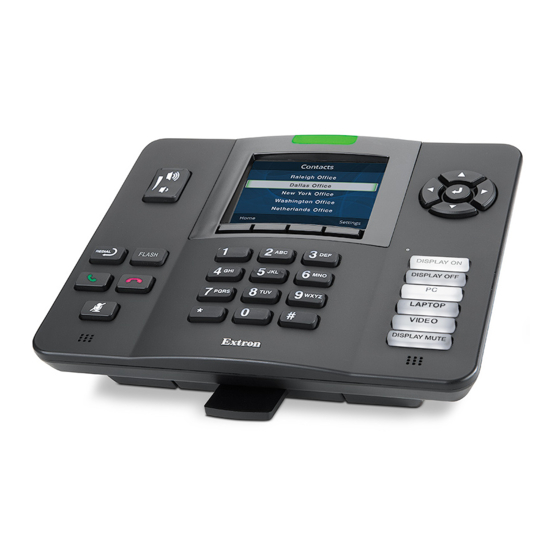
Page 13: Panel Features
Panel Features This section contains enclosure features. Topics in this section include: Front Panel Features • • Rear Panel Features Front Panel Features The CCI Pro 700 comes with installed buttons for common functions (see Button Replacement on page 22 for information on changing the buttons). However, button functions are not assigned until configured in Global Configurator Plus and Professional (see the Global Configurator Help file). -
Page 14: Rear Panel Features
Dial buttons — Start or end conference calls (see figure on the previous page). Mic mute button — Mutes or unmutes conference room microphones (see on the previous page). Number keypad buttons — Consist of alphanumeric characters for dialing phone numbers or entering values (see Navigation buttons —... -
Page 15: Rear Panel Buttons And Connector
Carefully lift the CCI Pro 700 away from the base. Figure 4. Removing the CCI Pro 700 From the Base Rear Panel Buttons and Connector Rear Panel Remove the device from the base to access the rear panel features (see Access on the previous page). - Page 16 Straight-through Cable Crossover Cable Pins: End 1 End 2 End 1 End 2 1 2 3 4 5 6 7 8 Pin Wire Color Pin Wire Color Pin Wire Color Pin Wire Color white-orange white-orange white-orange white-green orange orange orange green white-green white-green...
- Page 17 ATTENTION: • The CCI Pro 700 is intended for connection to a Power over Ethernet circuit for intra-building use only and are considered to be part of a Network Environment 0 per IEC TR62101. • Le CCI Pro 700 est conçu pour une connexion à un circuit PoE pour une utilisation intérieure seulement et est considéré...
-
Page 18: Cable Routing
Cable Routing Rear Panel Access Remove the CCI Pro 700 from the base (see on page 6). Pull the twisted pair cable through the opening at the bottom of the base (see figure 8). Figure 8. Routing Cable through the Base Opening Connect the cable to the LAN and PoE connector (see figure on page 7) -
Page 19: Setup Menu
Setup Menu This section contains basic setup information using the setup menu system. Topics in this section include: • Navigation and Data Entry • Setup Menu System Navigation and Data Entry • Menu button — Press the Menu button (see figure on page 7) to access or exit the setup menu. -
Page 20: Setup Menu System
Setup Menu System The setup menu contains four submenus for configuring the CCI Pro 700 and one to display information about the CCI Pro 700. The available submenus include: • Status Submenu • Network Submenu • Display Submenu • Audio Submenu Advanced Submenu •... -
Page 21: Network Submenu
Network Submenu This submenu (see figures 11 and 12) contains options to configure network settings. Network settings can be assigned automatically with Dynamic Host Configuration Protocol (DHCP) or manually by specifying an IP address, subnet mask, gateway address, and Domain Name Server (DNS) IP address obtained from the network administrator. To finalize pending changes, press the Context button directly below Apply. -
Page 22: Display Submenu
Figure 12. Network Submenu — Page 2 DNS (IP) — Press the Navigation button to edit the DNS address. Use the • ◄ and ► Navigation buttons to move the cursor position and the Keypad to enter values. The range is 0.0.0.0 to 255.255.255.255 (the default is 127.0.0.1). •... -
Page 23: Audio Submenu
Wake on motion mode — Press the ◄ or ► Navigation button to enable or • disable wake on motion mode. When enabled, the device deactivates sleep mode when motion is detected near the device. Audio Submenu This submenu (see figure 14) contains options to adjust all audio settings. Figure 14. -
Page 24: Advanced Submenu
Advanced Submenu This submenu contains options to set a menu lockout PIN number and display GUI projects and system information. Figure 15. Advanced Submenu — Page 1 Menu PIN mode — Press the ◄ or ► Navigation button to enable or disable the •... - Page 25 Figure 17. Advanced Submenu — Page 2 Name — Displays the name of the loaded Global Configurator file. • • Version — Displays the Global Configurator version number. • Creation date — Displays the date the Global Configurator file was created in the format MM/dd/yyyy hh:mm:ss, where MM is the month and mm is the minutes.
-
Page 26: Configuration Software
Configuration Software This section contains basic information about downloading and installing GUI Designer, Global Configurator Plus and Professional, Toolbelt, and Global Scripter, as well as basic information about using them. For more information on the programs, see their respective help files. Topics in this section include: Configuration Software Programs •... -
Page 27: Software Overview
Software Overview To design a graphical user interface (GUI) for the CCI Pro 700 and configure button functions, perform the following steps: Download and install GUI Designer and Global Configurator Plus and Professional, Toolbelt, or Global Scripter, as desired, to a computer connected to the same network as the control processor and CCI Pro 700 (see Software Download below and... -
Page 28: Software Installation
Click the Download link to the right of the desired software. If requested, submit any required information to start the download. Note where the file is saved. NOTE: An Extron Insider account is required. Software Installation Open the software executable (.exe) file. Follow the instructions that appear on the screen. -
Page 29: License Information
License Information The interface uses various licensed third-party software packages during operation. To view details about third-party packages and associated licensing, perform the following: In the General Status panel, click the License Information button. The License Information dialog box opens. Figure 21. -
Page 30: Reference Information
Reference Information This section contains reference information. Topics in this section include: Mounting • • Network Port Requirements • Button Replacement • Reset Modes • Firmware Download Mounting The CCI Pro 700 can be placed on a flat surface such as a tabletop. Network Port Requirements See the Network Ports and License Information guide on the Extron website. - Page 31 To replace button labels, perform the following: Remove the CCI Pro 700 from the base (see Rear Panel Access on page 6). Disconnect power from the CCI Pro 700. Remove the seven screws from the rear panel. Figure 22. Rear Panel Screws Remove the front panel.
-
Page 32: Reset Modes
Reset Modes The recessed Reset button (see figure 5 on page 7) on the rear panel resets the interface according to the table below. If necessary remove the interface from the base (see Rear Panel Access on page 6). Use an Extron Tweeker or small screwdriver to press and release the button. -
Page 33: Firmware Download
Firmware Download Figure 24. Downloading Firmware from the Extron Website On the Extron website, click the Download tab ( On the left sidebar, click the Firmware link ( Navigate to the CCI Pro 700. Ensure the available firmware version is a later version than the current one on the device. - Page 34 Extron Electronics makes no further warranties either expressed or implied with respect to the product and its quality, performance, merchantability, or fitness for any particular use. In no event will Extron Electronics be liable for direct, indirect, or consequential damages resulting from any defect in this product even if Extron Electronics has been advised of such damage.
Need help?
Do you have a question about the TouchLink CCI Pro 700 and is the answer not in the manual?
Questions and answers