
Subscribe to Our Youtube Channel
Related Manuals for JUMO LOGOLINE 500d


Summary of Contents for JUMO LOGOLINE 500d
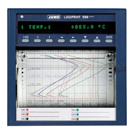
- Page 1 LOGOLINE 500d Pen recorder with text printing and LED dot matrix display B 70.6021.0 Operating Manual 2011-01-19/00331468...
- Page 2 Levels and key functions Key functions - Chart fast forward when recording is stopped (in basic status) - Aborting parameter input (Exit) - Level change backwards - Start/Stop recording - Decimal place selection during value input - For text input: rapid character selection (jump to “...
-
Page 3: Table Of Contents
Contents About this Manual Introduction ......................6 Arrangement of the documentation ................ 7 Typographical conventions ..................8 1.3.1 Warnings ........................8 1.3.2 Notes ........................8 1.3.3 Presentation ......................9 Identifying the instrument version Instrument description .................... 10 Type designation ....................11 Accessories ...................... - Page 4 Contents Programming Basic status ......................47 Operating level ....................... 49 8.2.1 Chart speed ......................50 8.2.2 Print test ........................51 8.2.3 Service print ......................52 8.2.4 Level inhibit and code request ................53 Parameter level ....................... 55 8.3.1 Language ........................ 56 8.3.2 Date and time ......................
- Page 5 Contents Consumables Summary of consumables ................... 105 Removing and replacing the chart cassette ............106 9.2.1 Changing the roll chart ..................108 9.2.2 Changing the fanfold chart ................... 109 Extra Codes and accessories 10.1 Converting the chart cassette ................110 10.2 Extra Code 259 .....................
-
Page 6: About This Manual
1 About this Manual Introduction Please read this Manual before starting up the instrument. Keep the Manual in a place which is at all times accessible to all users. Please assist us to improve this Manual where necessary. Your suggestions will be most wel- come. -
Page 7: Arrangement Of The Documentation
1 About this Manual Arrangement of the documentation The documentation for this instrument con- sists of the following parts: Operating Manual B 70.6021.0 This Operating Manual is always supplied with the instrument. It is addressed to the OEM (original equipment manufacturer) and to the user with appropriate technical know-how. -
Page 8: Typographical Conventions
1 About this Manual Typographical conventions 1.3.1 Warnings The signs for Danger and Warning are used in this Manual under the following con- ditions: Danger This symbol is used when there may be danger to personnel if the instruction is disregarded or not followed accurately. -
Page 9: Presentation
1 About this Manual Action This symbol indicates that an action is being described. The individual steps are indicated by this symbol, e.g.: * press key * enter with 1.3.3 Presentation Keys Keys are shown as boxes. Both symbols and text are possible. Where a key has mul- tiple functions, the text shown is the one corresponding to the actual fuctions dis- cussed. -
Page 10: Identifying The Instrument Version
2 Identifying the instrument version Instrument description The pen recorder provides 1, 2 or 3 chan- nels for recording; the channels are isolated from each other by optocouplers. Channel 1 can be used to write text in addition to the signal trace. -
Page 11: Type Designation
706021 LOGOLINE 500d with 1 universal input and text output 706022 LOGOLINE 500d with 2 universal inputs and text output (via channel 1) 706023 LOGOLINE 500d with 3 universal inputs and text output (via channel 1) (2) Inputs 1 — 3 (programmable) -
Page 12: Accessories
2 Identifying the instrument version Standard accessories - 1 Operating Manual B 70.6021.0 - 2 Mounting brackets - 3 cable-tie with foot (can be released) for tension relief of the sensor leads connected - 1 Fibre pen, disposable, for each channel - 2 Chart rolls 16m long 1 Chart roll 32m long (with Code r32) -
Page 13: Installation
3 Installation Location and climatic conditions The instrument location should as far as possible be free from shock and vibration. Stray electromagnetic fields, e.g. from mo- tors, transformers etc., should be avoided where possible. The ambient temperature at the location may be between –10 and+50 °C at a relative humidity not exceeding 75 %, without con- densation. -
Page 14: Fitting In Position
3 Installation Fitting in position Side view (dimension 26 increased to 27 when using the IP65 seal) Front view inch 22.5 0.89 1.42 3.94 4.25 4.33 4.72 5.35 Panel cut-out +0.04 5.43 5.67 8.94 16 m 53 ft 32 m 107 ft 1.5 mm 0.0025 in... -
Page 15: Electrical Connection
4 Electrical connection Notes on installation The choice of cable, the installation and Earth the instrument at terminal PE to the electrical connection of the instru- the earth conductor. This line should ment must conform to the requirements have at least the same cross-section as of VDE 0100 “Regulations on the Instal- the supply lines. -
Page 16: Connection Diagram
4 Electrical connection Connection diagram The electrical connection must only be carried out by properly qualified personnel. Rear view with screw-clamp connectors Terminals Supply as on label N neutral (L-) L1 line L1 (L+) PE potential earth Analogue inputs Input 1 Input 2 Input 3 Field... - Page 17 4 Electrical connection Analogue inputs Input 1 Input 2 Input 3 Resistance thermometer/ Field Field Field potentiometer in 2-wire circuit comp line Resistance thermometer/ potentiometer in 3-wire circuit Resistance thermometer/ potentiometer in 4-wire circuit Resistance transmitter A = start with 3-wire connection S = slider E = end Field...
-
Page 18: Starting Up
5 Starting up Display and controls 24-position 5x5 dot matrix LED display fibre pen, channel 3, green fibre pen, channel 2, red fibre pen, channel 1, blue chart (10) setup interface (behind swing-up LED dot matrix display) keys for operation and programming door housing to DIN 43700 for flush panel mounting, galvanised steel... -
Page 19: Fitting The Fibre Pens
5 Starting up Fitting the fibre pens * Open the recorder door * Stop recording (e.g. press key * Swing display upwards * Slide the fibre pen into the holder up to the stop * Swing display down again until it clicks home. -
Page 20: Preparation
6 Preparation Operating modes and status Operating mode/status Description Basic status Basic status of the recorder with signal acquisition and processing. The display shows, depending on setting: - instrument designation, date and time - one channel and its measurement as number or bargraph - or status/error messages. - Page 21 6 Preparation Operating mode/status Description Timed operation This chart speed applies within a programmable time period. Outside this period the chart is advanced at the speed programmed as normal speed. Section 8.5.4 Section 10.4 Recording Scaling The scale can be printed in two different modes: cyclic: for each channel at a configured spacing triggered: for all channels by pressing key (key F,...
-
Page 22: Operating Principle
6 Preparation Operating principle The individual parameters and functions are divided into three levels for clearer operation of the recorder: Basic status Basic status of the recorder with signal ac- quisition, recording, indication and process- ing. The display shows, depending on setting: - instrument designation, date and time (the time can be switched off via the para- meter parameter level... - Page 23 6 Preparation Parameter level The parameter level is protected by a code- number to prevent unauthorised access. There are two different codenumbers: - Codenumber for limited parameter set - Codenumber for complete parameter set Section 8.2.4 Section 12.6 If a wrong codenumber is input, the individ- ual parameters can be viewed, but not pro- grammed.
- Page 24 6 Preparation Configuration level 1 If a correct codenumber has been input when calling up the parame- ter level, the recorder interrupts signal acquisition and recording at this level. The parameters can be viewed and altered. Configuration level 1 includes the following channel-specific parameters: - writing status - signal input...
- Page 25 6 Preparation Configuration level 2 If a correct codenumber has been input when calling up the parame- ter level, the recorder interrupts signal acquisition and recording at this level. The parameters can be viewed and altered. Configuration level 2 includes the following global parameters: - instrument designation - chart speed programming mode...
- Page 26 6 Preparation Configuration level 3 If a correct codenumber has been input when calling up the parame- ter level, the recorder interrupts signal acquisition and recording at this level. The parameters can be viewed and altered. Configuration level 3 includes parameters which belong to Extra Codes and the maths module.
- Page 27 6 Preparation The levels, parameters and subparameters are arranged in a tree structure. Starting from the basic status the program branches to the individual levels and from there into the corresponding parameters, and also into any sub-parameters. To alter a certain parameter, run through the relevant levels up to this parameter.
- Page 28 6 Preparation Entering parameters Key functions Where there are no further sub-parameters, - Chart fast forward when recording is stopped transfers all the data of the parame- (in basic status) ter to the memory. - Aborting parameter input (Exit) Aborting programming - Level change backwards Programming can be aborted within a pa- - Start/Stop recording...
- Page 29 6 Preparation Selection Selection consists of a list of several options. Three keys are used to select an option: * select option with the * enter selection with Value/text input Five keys are used to input values: * select the digit to be altered with the keys * increment and decrement the selected diget with the...
-
Page 30: Text Printing
7 Text printing The pen recorder can print text in addition to the trace using the fibre pen of channel 1. Text printing is used for comments on the trace and for event recording. The charac- ters are written in dots on a 9 x 7 matrix. Printing priorities There are various types of text which are as- signed priorities in the setup program. - Page 31 7 Text printing Only the latest request is stored for each text. Example: A report with high priority is being printed from 12:00 to 12:05 hrs. While it is being printed a relay goes overlimit twice. Under normal conditions three texts would be printed for this overlimit (low priority), as follows: “12:01 relay 1 ON”,...
- Page 32 7 Text printing In the following cases all existing text print- ing requests are cancelled and new ones received are ignored: - recorder goes to stop status - print test is started - service print is started - recorder is switched off An exception is the statistical report: ...
-
Page 33: Printing Modes
7 Text printing Printing modes There are two modes for printing text: - trace is interrupted - trace is overwritten Interrupting the trace The text is printed as quickly as possible. During text printing there is no recording of the trace on channel 1. The chart speed is optimised for text printing;... - Page 34 7 Text printing Overwriting the trace The text is printed at the normal chart speed. There is only a brief interruption of the channel 1 trace. No text printing at zero chart speed and at a chart speed above 360mm/h. Printing a text line requires different times, depending on the programmed chart speed.
-
Page 35: Clock Time
7 Text printing Clock time This is printed cyclically at a configurable spacing. The following spacings can be set: _00:00 05.11.96 4 cm approx. 6 cm approx. _23:00 12 cm approx. no time printing The spacings are independent of the select- ed chart speed. -
Page 36: Scaling
7 Text printing Scaling The scaling can be printed in two ways: cyclic: for each channel at a configured spacing triggered: for all channels on pressing the key (hold down for at least 4 sec) or by closing one of the log- ic inputs. - Page 37 7 Text printing Example: a) upper chart - channel 1 -200.0 +325.0 +850.0 Ch.1 (blue): Furnace 1 °C - range: 0 — 100 mm - relay limits at 200 and 500 °C b) lower chart - channel 2 +200.0 +400.0 - restricted range: 50 —...
-
Page 38: Changing The Chart Speed
7 Text printing Changing the chart speed Every change in chart speed is reported by printing a line with the current time and the new chart speed. The type of line indicates the type of chart _12:34 240 mm/h speed with which recording takes place af- ter the change. - Page 39 7 Text printing Text printing in the trace overwriting mode ( Section 7.2) may take a very long time. In order that the chart speed change is not delayed, the priority of texts printed in this mode should be lower than the priority of the chart speed change.
-
Page 40: Recording Start And End
7 Text printing Recording start and end Recording start and end are reported by a start and end text which can be programmed. Text printing for start and end can be _13:20 06.11.96 Recording start switched on and off separately. _12:34 06.11.96 Recording stop... -
Page 41: External Text, Binary-Linked Text, Relay Texts
7 Text printing External text, binary-linked text, relay texts Extra Code 259 required. 12:34 Overload External text Eight logic inputs are available for external texts. Closing a logic input causes the corre- sponding text to be printed. Opening the logic input has no effect. - Page 42 7 Text printing Relay texts Relay texts are printed when a relay switches. The request for printing a relay text is ignored if the text consists only of blank characters. There is also no printing of the corresponding time. ...
-
Page 43: Incrementing The Event Counter
7 Text printing Incrementing the event counter Any logic input is assigned to the event counter. Each closing of the corresponding logic input increments the event counter. It 12:34 Batch No. 00023 can be preset using the setup program. Each incrementing is reported by printing the clock time and the programmed text, fol- lowed by the current counter reading. -
Page 44: Statistical Report
7 Text printing Statistical report This report is printed at the end of the statis- tical period. Recorder designation Report start (Date + time) Report end (Date + time) MIN. MAX. AVER. DIM. Section 8.5.8 Name Ch.1 Min. value 1 Max. -
Page 45: Print Test
7 Text printing 7.10 Print test The print test can only be initiated on the re- corder using the keys. It is used to check the function of writing system and fibre pens. Started text printing is aborted and not continued after the print test. -
Page 46: Service Print
7 Text printing 7.11 Service print The service print can only be initiated on the recorder using the keys. SERVICE PRINT It prints the software version, the number of software version : 078.02.01.2 supply interruptions and the total operating no. of power downs: 00012 time of the recorder in hours. -
Page 47: Programming
8 Programming Basic status The recorder is in the basic status after the supply has been applied and it has been in- itialised. The measurement signals are ac- quired, processed and recorded. In the basic status the following are indicat- ed, depending on the setting: - the instrument designation, date and time (the time can be switched off via the para-... - Page 48 8 Programming Pressing the key in the stop status ac- tivates the chart fast forward. Pressing the key (hold down at least 4 sec) starts the scaling print-out. Pressing the keys simultaneously changes to the operating level.
-
Page 49: Operating Level
8 Programming Operating level The operating level is used to perform sim- ple operating actions. It is reached from the basic status by press- ing the keys simultaneously, from the parameter level by pressing the key. The operating level includes the following parameters: - chart speed - print test... -
Page 50: Chart Speed
8 Programming 8.2.1 Chart speed The standard chart speed for signal tracing is set here. The chart speed is selected in steps from a table of standard chart speeds, or can be programmed continuously to any value be- tween 0 and 7200 mm/h. Standard chart speeds are: 0, 5, 10, 20, 60, 120, 240, 300, 360, 600, 720, 1800, 3600 und 7200 mm/h. -
Page 51: Printtest
8 Programming 8.2.2 Print test Print test is used to check the function of writing system and fibre pens. Print test can only be initiated on the record- er using the keys. PRINTTEST = ON continues until it is terminated by PRINTTEST = OFF. ... -
Page 52: Service Print
8 Programming 8.2.3 Service print The service print prints the software version, the number of supply interruptions and the total operating hours of the recorder. It can only be initiated on the recorder using the keys. Started text printing is aborted and is not continued after the service print. -
Page 53: Level Inhibit And Code Request
8 Programming 8.2.4 Level inhibit and code request The parameter level is protected by a 4-digit codenumber. Two codenumbers are available: - codenumber for a limited set of parameters (factory-set to 9200) - codenumber for a full set of parameters (factory-set to 9210) Which parameters belong to the limited set of parameters is defined in the set-up pro-... - Page 54 8 Programming If a wrong codenumber is entered, the recorder remains in normal op- eration. Signal acquisition, process- ing and recording remain activated. The parameters can be viewed but not programmed. The codenumbers can be altered in the setup program under Edit ...
-
Page 55: Parameter Level
8 Programming Parameter level At the parameter level it is possible to con- figure general parameters. From the operating level, the parameter lev- el is reached by simultaneously pressing keys , from the configuration level 1 by pressing the key. The parameter level covers the following pa- rameters: - language... -
Page 56: Language
8 Programming 8.3.1 Language There is a choice of the following languages: - English - French - German The language setting affects all non-pro- grammable texts in the recorder which are printed or indicated. Display Edit Selection/input with keys Edit Continue with LANGUAGE Language: ENGLISH... -
Page 57: Date And Time
8 Programming 8.3.2 Date and time Programming the system clock of the re- corder. The following are programmed: day, month, year, weekday, hour and minute. The current clock time is printed at certain events. It serves as reference time for timed events, such as statistical reports, timed operation and summer time. -
Page 58: Summertime
8 Programming 8.3.3 Summer time Input of a time interval during which the system clock of the recorder is changed to summer time. Example: Summer time start: 31.03.96, 2:00 hrs Summer time end: 27.10.96, 3:00 hrs On 31.03.96 at 2:00 hrs the system clock is advanced automatically one hour to 3:00 hrs. -
Page 59: Display Brightness
8 Programming 8.3.4 Display brightness The brightness of the display can be pro- grammmed in four different steps. Display Edit Selection/input with keys Enter Continue with DISPLAY BRIGHTNESS: STEP forwards 1...4 backwards... -
Page 60: Relay Limits
8 Programming 8.3.5 Relay limits This parameter is only visible when the recorder is fitted with the inter- face for the external relay module ER8 (extra Code 259 is required) For each relay, a separate limit value is pro- grammed at which it switches on or off. -
Page 61: Display Of Time
8 Programming 8.3.6 Display of time The parameter “Display time” has been added to the parameter level with effect from the instrument version 078.03.01.1. The time is indicated on the display when the recorder is in the basic status. The time display can be suppressed (status = OFF) by using this parameter. -
Page 62: Configuration Level 1
8 Programming Configuration level 1 At the configuration level 1 it is possible to configure channel-specific parameters. From the parameter level, the configuration level 1 is reached by simultaneously press- ing keys , from the configuration level 2 by pressing the key. -
Page 63: Writing Status
8 Programming 8.4.1 Writing status Setting for each recording channel: whether the trace is printed on the chart and appears in the statistical report or not. Display Edit Selection/input with keys Enter Continue with PLOTSTATE 1 PLOTSTATE Select number of the recording channel ... -
Page 64: Measurement/Signal Input
8 Programming 8.4.2 Measurement/signal input The input signal/sensor type is selected and the measurement ranges as well as the filter time constants for each input channel are defined. If customized tables are used for the linearisation of the input signals, the measurement inputs and the customized tables have to be set us- ing the setup program. - Page 65 8 Programming Display Edit Selection/input with keys Enter Continue with 1 CHARACT: Pt100 customized X1 or X2: Pt 100 (–200 to +850°C) (RES.THERM.) 10 (FILTER) Pt 100 (–200 to +649°C, JIS) Pt 500 (–200 to +850°C) otherwise: Pt 1000 (–200 to +850°C) ...
- Page 66 8 Programming Display Edit Selection/input with keys Enter Continue with (Continued: 1 CHARACT.:L customized INPUT) X1 or X2: (–200 to +900°C) (THERMO- 10 (FILTER) (–210 to +1200°C) COUPLE) (–200 to +600°C) otherwise: (–270 to +400°C) (–270 to +1372°C) (–270 to +1000°C) (–270 to +1300°C) (–50 to +1768°C)
- Page 67 8 Programming Display Edit Selection/input with keys Enter Continue with 1 CHARACT.: linear customized X1 or X2: linear (POTENTIO- 10 (FILTER) (customized lin. 1) METER) (customized lin. 2) otherwise: 1 CONNECTION: 2/3-wire 2/3-wire 4-wire Define type of potentio- meter connection: (2/3-wire circuit or 4-wire circuit)
- Page 68 8 Programming Display Edit Selection/input with keys Enter Continue with (Continued: 1 CHARACT.: linear linear INPUT) characteristic: linear (RES. TRANS- (customized lin. 1) MITTER) (customized lin. 2) customized X1 oder X2: 10 (FILTER) 1 Ra: +300.0 Ohm Check Input start resistance...
- Page 69 8 Programming Display Edit Selection/input with keys Enter Continue with (Continued: 1 CHARACT.: linear customized INPUT) or X2 linear (VOLTAGE) Pt 100 (–200 to +850°C) 10 (FILTER) Pt 100 (–200 to +649°C, JIS) otherwise: Pt 500 (–200 to +850°C) ...
- Page 70 8 Programming Display Edit Selection/input with keys Enter Continue with 1 TEMP .: °C °C, °F (only with ther- mocouples resistance thermometers 1 TEMP . BEG: -200.0 °C Check Input start of temp. start temperature range according to characteristic ...
- Page 71 8 Programming Display Edit Selection/input with keys Enter Continue with (Continued: 1 CHARACT.: linear customized. INPUT) or X2 linear (CURRENT) Pt 100 (–200 to +850°C) 10 (FILTER) Pt 100 (–200 to +649°C, JIS) otherwise: Pt 500 (–200 to +850°C) ...
- Page 72 8 Programming Display Edit Selection/input with keys Enter Continue with 1 RANGE END: linear +020.0 mA characteristic: Check 10 (FILTER) Input end of range end measurement range otherwise: (–20,5mA ≤ range end < 20.5mA 0.0mA ≤ range end ≤...
-
Page 73: Scaling
8 Programming 8.4.3 Scaling The scaling start/end value and the dimen- sion (unit) are defined to record the meas- urement. For the alpha-numerical presenta- tion of the measurement on the display and on the chart, the number format is selected. ... -
Page 74: Channel Designation
8 Programming 8.4.4 Channel designation Defines the channel designation for each re- cording channel. During scaling the desig- nation is printed on the chart and shown on the display together with the measurement value. The complete character set is availa- ble. -
Page 75: Limit Operation
8 Programming 8.4.5 Limit operation On overlimit or underlimit, the chart print-out is continued with the chart speed set under parameter LIMIT FEED (v Section 8.5.3). Status and limits are set separately for each channel. A switching differential of 0.5% is set about the switching point to avoid that the chart speed is changed too frequently. -
Page 76: Plotarea (Zoom)
8 Programming 8.4.6 Plotarea (zoom) Defines the range of the input signal to be recorded on the chart. The complete range or an enlarged section can be recorded. In- put is in percent. The low value designates the point of the measurement range which becomes the new zero. -
Page 77: Presentation Range (Offset)
8 Programming 8.4.7 Presentation range (offset) Defines the range on the chart on which a trace is to be recorded. Either the entire width of 100 mm or a strip can be selected for the display. Sets the start and end of the trace on the chart. -
Page 78: Configuration Level 2
8 Programming Configuration level 2 At the configuration level 2 it is possible to configure global parameters. From the configuration level 1, the configu- ration level 2 is reached by simultaneously pressing keys , from the configura- tion level 3 by pressing the key. - Page 79 8 Programming Signal acquisition, processing and recording are interrupted. The relays of the external relay mod- ule ER8 remain in their current sta- tus. They are only operated again when the recorder is at the operating level or in the basic status. Display Edit Selection/input...
-
Page 80: Instrument Designation
8 Programming 8.5.1 Instrument designation Defines the instrument or system designa- tion. The complete character set is availa- ble. (v Section 12.5). Display Edit Selection/input with keys Enter Continue with UNITWORD TEXT: _ _ _ _ _ _ _ _ _ _ forwards Input instrument desig- backwards... -
Page 81: Speed Programming Mode
8 Programming 8.5.2 Speed programming mode For programming the chart speed, this pa- rameter is used to choose between stand- ard steps, i.e. selection of a chart speed from a table of values, and continuous pro- gramming of the speed (speed program- ming in unit steps). -
Page 82: Speed Limit Operation
8 Programming 8.5.3 Speed limit operation Chart speed on limit operation. It is possible to change to this chart speed, if the signal goes above/below the limit values entered under the parameter LIMIT FEED. Please observe priorities within the different chart speeds. -
Page 83: Timed Operation
8 Programming 8.5.4 Timed operation Chart speed which is only valid within the entered time span. On reaching the start time, the chart speed is changed over to the value configured here. When the end time has been reached, the chart speed is switched back to the stand- ard chart speed. -
Page 84: Scale Printing
8 Programming 8.5.5 Scale printing Defines the regular spacing in which the scaling is to be printed on the chart. The val- ues which are set are guide values and may differ according to the chart speed. Scale printing can also be started manually on the recorder. -
Page 85: Time Printing
8 Programming 8.5.6 Time printing Defines the spacing in which the time is to be printed on the chart. The values which are set are guide values and differ accord- ing to the chart speed. Section 7.3 Display Edit Selection/input with keys Enter Continue with... -
Page 86: Pen Offset Compensation
8 Programming 8.5.7 Pen offset compensation There is an offset of 2mm each between the fibre pens from channel 1 to channel 2 and from channel 2 to channel 3. This offset is compensated by a buffer storage of the measured values when the pen offset com- pensation is switched on. -
Page 87: Statistical Report
8 Programming 8.5.8 Statistical report Keeping statistics with a print-out of a table of statistics at the end of the statistical period. (v Section 7.9). The statistical period as well as the starting time for the print-out of the table of statistics are printed here. -
Page 88: Text At Beginning
8 Programming 8.5.9 Text at beginning Defines the text which is printed after a stop at the re-start of the recording (v Section 7.6). The complete character set is availa- ble. (v Section 12.5). Display Edit Selection/input with keys Enter Continue with BEGIN TEXT STATE: ON... -
Page 89: Text At End
8 Programming 8.5.10 Text at end Defines the text which is printed after a stop command before reaching the stop status. (v Section 7.6). The complete character set is available. (v Section 12.5). Display Edit Selection/input with keys Enter Continue with END TEXT STATE: ON OFF:... -
Page 90: Presetting
8 Programming 8.5.11 Presetting Presets the parameter/configuration data for commissioning and re-commissioning the recorder. The instruments are supplied fac- tory-set with this setting. This does not apply to the custom- ized linearisation tables. Display Edit Selection/input with keys Enter Continue with PRESETTING PRESETTING:... -
Page 91: Codenumber
8 Programming 8.5.12 Codenumber Exchanges JUMO codenumbers for cus- tomized codenumbers. Two different codenumbers are available: - The codenumber for a restricted parameter set (factory-set to 9200). - The codenumber for a complete parameter set (factory-set to 9210). The parameters which belong to the restrict-... -
Page 92: Configuration Level 3
8 Programming Configuration level 3 At the configuration level 3 parameters of the Extra Codes and the maths and logics module are configured. It is reached from configuration level 2 by si- multaneously pressing the keys. The configuration level 3 covers the follow- ing parameters: - relay outputs - maths and logics module... -
Page 93: Relay Output
8 Programming 8.6.1 Relay output Extra Code 259 is required. Accessory “External relay module ER8” is required. The external relay module ER8 is connected to the recorder via a serial interface. It adds 8 switching outputs to the recorder. The channels which are recorded can be freely assigned to relays 1 to 8. - Page 94 8 Programming Display Edit Selection/input with keys Enter Continue with 2 REL3 HYST.H: x.xxx Input differential right of the limit 2 REL3 LK: LK7 Select limit comparator function: LK7, LK8 2 REL3 SENS BR: CONST.
-
Page 95: Maths And Logics Module
8 Programming 8.6.2 Maths and logics module Sets the status of the maths and logics module.. The recorder response can, in prin- ciple, change when the maths and logics module is switched on. The information given in the Operat- ing Manual can then become partial- ly invalid. -
Page 96: Interface
8 Programming 8.6.3 Interface Extra Code 52 or 53 is required. Sets the parameters of the RS 422/RS 485 interface: - protocol - baud rate - data format - instrument address - minimum response time The minumum response time is the mini- mum time span between the query of an in- strument in a data network and the answer of the pen recorder. - Page 97 8 Programming Display Edit Selection/input with keys Enter Continue with ADDRESS: 001 Select address: Check: 1 — 255 ≤ address ≤ MIN. RESPONSE TIME: forwards 000Tmsec backwards Check: Select minimum ≤ resp.time response time: ≤ 0 — 999 msec...
-
Page 98: External Text
8 Programming 8.6.4 External text Extra Code 259 is required. A signal at one logic input (external contact) can prompt the recorder to print a text/ commentary which is programmed here. Section 7.7 Display Edit Selection/input with keys Edit Continue with ... -
Page 99: Binary-Linked External Text
8 Programming 8.6.5 Binary-linked external text Extra Code 259 is required. The signals which are present at the first four logic inputs are interpreted as a binary number. A text of 16 characters can be as- signed to each of these 16 possible binary numbers (2 = 16). -
Page 100: External Stop
8 Programming 8.6.6 External stop Extra Code 259 is required. Stops the recorder via a signal at the logic input. As long as the signal is present, the recording is interrupted. Display Edit Selection/input with keys Enter Continue with EXTERNAL STOP CONTACT: LOG.INPUT 3 forwards... -
Page 101: External Speed
8 Programming 8.6.7 External speed Extra Code 259 is required. The chart speed changed to when the logic input which has the function FEED EXTERN assigned to it is closed. Display Edit Selection/input with keys Enter Continue with FEED EXTERN CONTACT: LOG.INPUT 3 OFF: Select logic input:... -
Page 102: Event Counter
8 Programming 8.6.8 Event counter Extra Code 259 is required. The recorder features two event counters which can each be assigned to a logic input. Any start value can be configured. When a signal is applied to the corresponding logic input (external contact), the counter is incre- mented by one each time, if it is switched on (status=ON). -
Page 103: External Scaling
8 Programming 8.6.9 External scaling Defines the logic input from which the scale printing is initiated. Section 7.4 Display Edit Selection/input with keys Enter Continue with EXTERNAL CONTACT: LOG.INPUT 3 forwards SCALING Select logic input: backwards LOG.INPUT 1 LOG.INPUT 2 LOG.INPUT 3 LOG.INPUT 4 LOG.INPUT 8... -
Page 104: External Report
8 Programming 8.6.10 External report Defines the logic input from which the statis- tics are compiled and the report is printed. Statistics are initiated by the recognition of the low-high edge, terminated with the rec- ognition of the high-low edge and printed out in table format. -
Page 105: Consumables
9 Consumables Summary of consumables Fibre pens, disposable blue, Part No.: 00309750 red, Part No.: 00309751 green, Part No.: 00309753 Roll chart overall width: 120 mm no name, % graduation, linear overall length: 16 m Packing unit: 5 rolls Part No.: 00331497 no name, % graduation, linear overall length: 32 m... -
Page 106: Removing And Replacing The Chart Cassette
9 Consumables Removing and replacing the chart cassette... - Page 107 9 Consumables - When inserting the chart cassette, take care that it is centered on the tear-off edge and – guiding it with the thumb and index finger – insert it into the cassette slot and push it up gently, until the holding/ejector catch snaps into position.
-
Page 108: Changing The Roll Chart
9 Consumables 9.2.1 Changing the roll chart... -
Page 109: Changing The Fanfold Chart
9 Consumables 9.2.2 Changing the fanfold chart * * * * * * * * * * * * * * * * * * * *... -
Page 110: Extra Codes And Accessories
10 Extra Codes and accessories 10.1 Converting the chart cassette... -
Page 111: Extra Code 259
10 Extra Codes and accessories 10.2 Extra Code 259 The extra Code 259 features 8 logic inputs, one electrically isolated supply for 2-wire transmitter and the serial interface for the external relay module ER8. The 8 logic inputs can be operated through floating contacts or at the following voltage levels: inactive 0—5V... -
Page 112: External Relay Module Er8
10 Extra Codes and accessories 10.3 External relay module ER8 The external relay module ER8 adds eight switching outputs to the recorder. The re- lays are freely assigned to the recorder channels in the setup program ( Section 10.4). The limit for each relay is programmed at the parameter level. - Page 113 10 Extra Codes and accessories L1 N (L+) (L-) Power ER 8 Error RxD RxD TxD GND...
- Page 114 10 Extra Codes and accessories The relay is energised when the measure- ment goes above the limit setting. as lk7 but relay action reversed.
-
Page 115: Setup Program
10 Extra Codes and accessories 10.4 Setup program The setup program provides convenient configuration of the recorder using an IBM- PC compatible PC. Hardware requirements: - IBM-PC or compatible computer - CPU from Intel 386 - 4 MB RAM - 3.5“ disk drive - hard disk (at least 6 MB free) - one free serial interface RS232 (data interchange) - Page 116 10 Extra Codes and accessories Plugging the setup connector into the recorder interrupts: - signal acquisition and - recording In addition: - events are no longer covered, - statistical reports are aborted and reset, - limit values are no longer moni- tored, and - the outputs are no longer operat- ed;...
-
Page 117: Maths And Logics Module
10 Extra Codes and accessories 10.5 Maths and logics module If the maths and logics module is deactivat- ed, the signals measured at the signal in- puts are recorded in accordance with the configuration of the signal inputs. If the maths and logics module is activated, the measured signals can be mathematically linked. -
Page 118: Interface (Rs422/Rs485)
10 Extra Codes and accessories 10.6 Interface (RS422/RS485) This interface is intended for communica- tion with higher-level systems (e.g. bus sys- tems). It is not the setup interface, which is used to transfer the data between the setup program and the pen recorder. The RS422/RS485 interface is described in detail in the Operating Manual B 70.6001.2. -
Page 119: Fault Finding
11 Fault finding 11.1 What to do if... Display or printing The value is outside the measuring range (Out Of Range) The transducer has been connected up incorrectly “>>>>>>” The signal inputs are configured incorrectly Probe break Instead of a value, the prin- The value can not longer be represented;... - Page 120 11 Fault finding Relay does not switch The signal inputs are not wired up according to the connection although limit is exceeded diagram Pen recorder and external relay module ER8 are not connected together correctly The switching differential at the limit has been disregarded The relay status is “OFF”...
-
Page 121: Appendix
12 Appendix 12.1 Technical Data Cold junction internal: Pt100 Accuracy of internal cold junction: ±1.0 °C Analogue inputs (measurement channels) external: cold junction thermostat The cold junction temperature is set in the Measurement time setup program to a constant value between 240 msec for all three channels –20 and +100 °C. - Page 122 12 Appendix Measurement accuracy: Current Currents can be measured in the following up to 130Ω: ±150 mΩ basic ranges: up to 390Ω: ±300 mΩ ±1.6 Ω up to 1600Ω: Basic ranges Measurement accuracy Ω up to 3900Ω: ±2 μ –4 ±20 μ...
- Page 123 12 Appendix General Data Chart cassette cassette for 16 m or 32 m roll chart or 16 m fanfold chart, with tear-off edge and electron- Zero adjustment ic chart end switch. self-compensating system using Hall sensors Chart Recording system roll or fanfold chart to DIN 16 230 drive by stepping motor overall width: 120 mm...
- Page 124 12 Appendix Power consumption Approvals/marks of conformity 35 VA max. Mark of conformity: c UL us Data back-up Testing laboratory: by lithium battery in RAM, more than 4 years; Underwriters Laboratories by storage capacitor 2 days at 15 — 25 °C Certificates/certification numbers: ambient temperature.
-
Page 125: Error Messages
12 Appendix 12.2 Error messages All error messages are displayed flashing on the matrix display at regular intervals. The other instrument functions remain unaf- fected as far as posssible. Display Cause / Remedy Status message NO PAPER! The chart cassette has been removed or the end of the chart has been reached;... - Page 126 12 Appendix Display Cause / Remedy Errors on parameter input ERROR! - Chart speed outside 0—7200mm/h. The input has to be repeated. Input a value within the range of values. - Date is invalid. An invalid date has been input. The input has to be repeated.
-
Page 127: Hardware Fault
12 Appendix 12.3 Hardware fault In case of one of the following faults the re- cording is aborted and the error message flashes on the display. The relays are operated as for probe break The recorder does not react to any event and can not be operated. -
Page 128: Status Messages
12 Appendix 12.4 Status messages The following status messages are indicat- ed on the matrix display: Display Description INITIALISING The recorder is being initialised. Please wait. STOP The recorder is in the Stop status because key has been pressed. EXTERNAL STOP The recorder is in the Stop status because external stop has been activated by closing the appropriate logic input. -
Page 129: Character Set
12 Appendix 12.5 Character set 0126 0212 Ô 0161 ¡ 0213 Õ " 0162 ¢ 0214 Ö 0163 £ 0215 × 0164 ¤ 0216 Ø 0165 ¥ 0217 Ù & 0166 ¦ 0218 Ú ’ 0167 § 0219 Û 0168 ¨... -
Page 130: Summary Of The Parameters
12 Appendix... - Page 131 12 Appendix...
-
Page 132: Index
13 Index current input 16, 64, 122 customized linearisation 64, 122 accessories 12 cyclic display 47 address 96 analogue inputs 16 data format 96 date and time 57 bargraph 47 decimal place 29, 73 basic status 22, 47 differential baud rate 96 limit operation 75 binary-linked external text 41, 99 relay output 93... - Page 133 13 Index location 13 logic inputs 111 fanfold chart 105 fault finding 119 faults, remedy of 119 fibre pen 105 maths and logics module 95, 117 filter time constant 65 measurement range 65–72 fitting fibre pen 19 measurement/signal input 64 fitting in position 14 front view 14 number format 73...
- Page 134 13 Index programming timed operation 83 abort 28 value input 29 binary-linked external text 99 writing status 63 channel designation 74 chart speed 50 chart speed limit operation 82 recording chart speed programming mode 81 pen offset compensation 21 codenumber, customized 91 plotarea (zoom) 21 configuration level 1 62 presentation range (offset) 21...
- Page 135 13 Index sub-parameters 27 tree structure 27 summary of parameters 130 type designation 11 summer time 58 typographical conventions 8 switching outputs 112 system clock 57, 58 unit 73 technical data 121 text input 29 value input 29 text printing 30 voltage input 16, 64, 122 abort criteria 30 chart speed 38...
- Page 140 JUMO GmbH & Co. KG JUMO Instrument Co. Ltd. JUMO Process Control, Inc. Street address: JUMO House 6733 Myers Road Moritz-Juchheim-Straße 1 Temple Bank, Riverway East Syracuse, NY 13057, USA 36039 Fulda, Germany Harlow - Essex CM20 2DY, UK Phone:...
Need help?
Do you have a question about the LOGOLINE 500d and is the answer not in the manual?
Questions and answers