
Related Manuals for JUMO LOGOSCREEN Series


Summary of Contents for JUMO LOGOSCREEN Series
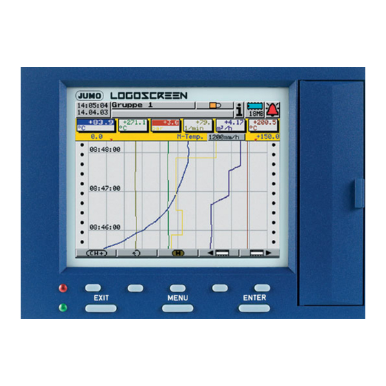
- Page 1 Paperless Recorder for secure acquisition of FDA-compliant measurement data B 95.5011.4 Installation Instructions 11.04/00415650...
- Page 2 Menu structure of the paperless recorder...
-
Page 3: Table Of Contents
Contents Introduction Preface ......................5 Arrangement of the documentation ............6 Typographical conventions ................. 8 Identifying the instrument version Nameplate ..................... 9 Type designation ..................10 Standard accessories ................11 Accessories ....................11 Installation Location and climatic conditions .............. 13 Mounting in position .................. - Page 4 Contents...
-
Page 5: Introduction
1 Introduction 1.1 Preface Please read these Installation Instructions before commissioning the instru- ment. Keep the instructions in a place that is accessible to all users at all times. Please assist us to improve these installation instructions, where necessary. Your suggestions will be appreciated. If any problems should occur during commissioning, please do not carry out any manipulations on the unit, as this could endanger your rights under the instrument warranty! -
Page 6: Arrangement Of The Documentation
The product description illustrates the safety and operating concepts behind description the system, and the results that can be achieved by JUMO in the course of the validation of an installation. It is intended to serve as an introduction to the system, and not as a formal technical documentation. - Page 7 This provides information on the connection of a paperless recorder to a com- pany-internal network. The description is incorporated in the B 95.5011.2.0 B 95.5011.2.1 Interface description (LON interface) This provides information on the connection and use of modules of the “JUMO mTRON automation system”. B 95.5011.2.3 Interface description (PROFIBUS-DP interface) This provides information on the connection of a paperless recorder to a PROFIBUS-DP system.
-
Page 8: Typographical Conventions
1 Introduction 1.3 Typographical conventions Warning signs The signs for Danger and Caution are used in this manual under the following conditions: Danger This symbol is used where there may be danger to personnel if the instruc- tions are disregarded or not followed accurately! Caution This symbol is used where there may be damage to equipment or data if the instructions are disregarded or not followed accurately! -
Page 9: Identifying The Instrument Version
2 Identifying the instrument version 2.1 Nameplate Identification Position The nameplate is affixed to the paperless recorder. Contents It contains important information such as: Description Designation on Example nameplate Instrument type 955011/10-888,000-51- 0032-0032-23,020 Sales number VARTN 95/00342163 Production number F-Nr 0022969000003130006 Supply voltage AC 110 …... -
Page 10: Type Designation
2 Identifying the instrument version 2.2 Type designation Paperless recorder for secure acquisition of FDA-compliant meas. data (1) Basic version 955011/00 paperless recorder, no analog inputs paperless recorder, no analog inputs, incl. PC 955011/01 software package and interface cable/adapter 955011/10 paperless recorder with 6 analog inputs paperless recorder with 6 analog inputs, incl. -
Page 11: Standard Accessories
2 Identifying the instrument version 2.3 Standard accessories - 1 Installation Instructions B 95.5011.4 - 1 Operating Instructions B 95.5011.1 - 2 mounting brackets - 4 cable-tie with foot (can be released) for strain relief of the sensor connection cables - 1 CD with additional documentation (see Chapter 1.2 “Arrangement of the documentation”) 2.4 Accessories... - Page 12 2 Identifying the instrument version...
-
Page 13: Installation
3 Installation 3.1 Location and climatic conditions The location should be as free as possible from shock and vibration. Stray electromagnetic fields from motors, transformers etc. should be avoided. The ambient temperature at the location can be 0 to +45°C, at a relative hu- midity of ≤75%, no condensation. - Page 14 3 Installation Fitting into min. 200 the panel Panel h Insert the paperless recorder from the front into the panel cut-out. Fitting in position h From the back of the panel, hook the two mounting brackets into the recesses on the sides of the housing. The flat sides of the brackets must be against the housing.
-
Page 15: Electrical Connection
4 Electrical connection 4.1 Installation notes The choice of the cable, the installation and the electrical connection must conform to the requirements of VDE 0100 “Regulations on the In- stallation of Power Circuits with nominal voltages below 1000V”, or the appropriate local regulations. -
Page 16: Procedure
4 Electrical connection 4.2 Procedure h Carry out electrical connection as per Chapter 4.3 “Connection diagram”. h Screw back panel cover on (spacer bolt first) h If necessary, use cable-ties for strain relief of connecting cables. -
Page 17: Connection Diagram
4 Electrical connection 4.3 Connection diagram The electrical connection must only be carried out by qualified personnel. Back panel Rear view with pluggable screw terminals (L-) (L+) Cover for back panel Hole for lead sealing Holes provided for the cable-ties supplied, for strain relief of the connection cables... - Page 18 4 Electrical connection Terminal assignment Connector Connection diagram Supply Supply voltage L1(L+) as per data sheet N (L-) Analog Thermocouple 1 to 12 inputs Resistance thermometer 1 to 12 in 2-wire circuit R =R Resistance thermometer 1 to 12 in 3-wire circuit Resistance thermometer 1 to 12 in 4-wire circuit...
- Page 19 4 Electrical connection Terminal assignment Connector Connection diagram Interfaces RS422 9-pole SUB-D socket (extra code) 3 TxD+ transmit data + 4 RxD+ receive data + 5 GND ground 8 TxD- transmit data - 9 RxD- receive data - RS485 9-pole SUB-D socket (extra code) 3 TxD+/RxD+ transmit/receive data + 5 GND ground...
- Page 20 4 Electrical connection Terminal assignment Connector Connection diagram Digital I/O Open-collector output (25V max., 100mA max.) (extra code) 3 ground 4 collector Logic inputs, voltage-operated 10 11 – (extra code) Example: LOW = -3 to +5V DC input 4 (terminal 8) HIGH = 12 to 30V DC contact-operated 1 +24V/50mA...
-
Page 21: Function Check
5 Function check When the paperless recorder is installed and connected, it can be started up. After the supply voltage has been connected or switched on, the start screen will appear briefly. Start screen After the end of the initialization phase, the visualization level is automatically started. - Page 22 5 Function check...
-
Page 23: Device Replacement / Software Update
6 Device replacement / software update If you need to replace the device or update the software, this chapter will help you back up and restore all necessary settings and parameters. h Fill in this page before replacing the device. Proof of Order number : _______________________________________________... - Page 24 6 Device replacement / software update Info After uploading the user list, the users must log in with the password that was initially assigned by the administrator. If a user no longer knows the password, then the user status has to be set to “New”...
-
Page 25: Technical Data
7 Technical data Analog inputs (channels 1 — 12) Thermocouple Designation Type Standard Range Linearization accuracy Fe-Con DIN 43 710 -200 to +900°C ±0.1% Fe-Con EN 60 584 -210 to +1200°C ±0.1% above -100°C Cu-Con DIN 43 710 -200 to +600°C ±0.1% above -150°C Cu-Con EN 60 584... - Page 26 7 Technical data Designation Standard Connection Range Linearization Measuring accuracy current Cu 50 2/3-wire -50 to +100°C ±0.5°C 500µA 2/3-wire -50 to +200°C ±0.9°C 250µA 4-wire -50 to +100°C ±0.5°C 500µA 4-wire -50 to +200°C ±0.6°C 250µA Connection type 2-, 3- or 4-wire circuit Shortest span 15°C max.
- Page 27 24V DC, 50mA (extra code) 1. with resistive load. SELV circuits and supply circuits must not be combined. External analog inputs / logic inputs / logic outputs Type JUMO mTRON automation system Sampling cycle 1sec Technical data see Data Sheet: 70.4015 Relay module...
- Page 28 7 Technical data Screen Resolution 320 x 240 pixels Size 5.7" Number of colors 27 colors Electrical data Supply 110 — 240V AC +10/-15%, 48 — 63Hz or (switch-mode power supply) 20 — 30V AC/DC, 48 — 63Hz Electrical safety to EN 61 010, Part 1 of August 2002 overvoltage category II, pollution degree 2 Test voltages (type test)
-
Page 29: Index
8 Index Accessories Analog inputs Back panel Climatic conditions Commissioning Connection diagram Cover for back panel Digital I/O Documentation, arrangement of Electrical connection Electrostatic discharge (ESD) Fitting into the panel Function check Identification of namplate Installation Installation notes Instrument documentation in PDF file format Instrument documentation in printed form Instrument version, identification of –... - Page 30 8 Index Nameplate Note signs Outline drawings PROFIBUS-DP Rear view Relay outputs Repeat order for recorder in the identical version Returning Sales documentation in printed form Standard accessories Start screen Supply Technical data Type designation Typographical conventions Visualization level Warning signs Warranty...
- Page 32 JUMO GmbH & Co. KG JUMO Instrument Co. Ltd. JUMO PROCESS CONTROL INC. Street address: JUMO House 885 Fox Chase, Suite 103 Moltkestraße 13 - 31 Temple Bank, Riverway Coatesville, PA 19320, USA 36039 Fulda, Germany Harlow, Essex CM20 2TT, UK...
Need help?
Do you have a question about the LOGOSCREEN Series and is the answer not in the manual?
Questions and answers