
Subscribe to Our Youtube Channel
Related Manuals for Beckman Coulter Cell Lab Quanta SC


Summary of Contents for Beckman Coulter Cell Lab Quanta SC
- Page 1 Cell Lab Quanta SC Instructions for Use PN 721742AD (October 2011) Manufactured for Beckman Coulter, Inc. 250 S. Kraemer Blvd. Brea, CA 92821...
- Page 2 This equipment is used in a manner other than specified. Operate the instrument as instructed in the Product Manuals. r You introduce software that is not authorized by Beckman Coulter into your computer. Only operate your system’s computer with software authorized by Beckman Coulter.
-
Page 3: Revision Status
This document applies to the latest software listed and higher versions. When a subsequent software version affects the information in this document, a new issue will be released to the Beckman Coulter website. For labeling updates, go to www.beckmancoulter.com and download the latest version of the manual or system... - Page 4 REVISION STATUS PN 721742AD...
-
Page 5: Table Of Contents
CONTENTS REVISION STATUS, iii CONTENTS, v Illustrations, xi Tables, xiii INTRODUCTION, xv Text Conventions, xvi Graphic Conventions, xvi Safety Symbols, xvii USE AND FUNCTION, 1-1 SYSTEM OVERVIEW, 1-1 INTENDED USE, 1-1 QUANTA SC SYSTEM OVERVIEW, 1-2 SYSTEM COMPONENTS, 1-3 PRINCIPLES OF OPERATION, 1-4 WARNING LABELS AND PRECAUTIONS, 1-5... -
Page 6: Contents
CONTENTS Electrical Input, 2-3 Ambient Temperature and Humidity, 2-3 Heat Dissipation, 2-3 Drainage, 2-4 INSTALLATION PROCEDURES, 2-4 Interunit Connections, 2-4 Lifting and Carrying, 2-4 OPERATION PRINCIPLES, 3-1 OVERVIEW, 3-1 SAMPLE FLOW, 3-1 SPECIFICATIONS, 4-1 PERFORMANCE SPECIFICATIONS, 4-1 Absolute Count, 4-1 Fluorescence, 4-1 Sizing, 4-1 Optics, 4-1... - Page 7 CONTENTS Menu Options, 5-4 File Menu, 5-5 Instrument Menu, 5-5 Gain Menu, 5-6 Volume Menu, 5-6 Analysis Menu, 5-6 Regions Screen, 5-7 Compensation Screen, 5-7 Protocols Screen, 5-8 Current Settings Screen, 5-8 File Information Screen, 5-9 Security Menu, 5-9 Help Menu, 5-10 Closing a Window or Closing the Software, 5-10...
- Page 8 CONTENTS Flushing, 7-17 Fill Cup, 7-18 Resetting Fluid Count, 7-18 Setting Up the Instrument, 7-19 Understanding the Instrument Setup Screen, 7-20 Understanding the Diagnostic Functions Screen, 7-22 Laser Control, 7-23 Understanding the Laser Control Options, 7-23 Importing Settings, 7-24 Understanding the Import Settings Screen, 7-25 Automatically Aligning the Optics, 7-25...
- Page 9 CONTENTS 7.10 WORKING WITH THE CURRENT SETTINGS SCREEN, 7-64 Defining Stop Sample Criteria, 7-64 Defining the Concentration (Use, # of Seconds, and Start Time), 7-65 Enabling/Disabling Checkboxes, 7-65 Defining Auto Save Options, 7-66 Customizing an Excel Report, 7-68 Pre-defined Excel Templates, 7-68 Creating/Modifying Text in Excel Report, 7-68...
- Page 10 10.8 ADJUSTING FUSE VOLTAGE, 10-17 TROUBLESHOOTING, 11-1 11.1 SYSTEM CONNECTIONS, 11-1 11.2 MONITOR VACUUM READINGS, 11-3 11.3 ERROR MESSAGES, 11-4 11.4 TROUBLESHOOTING GUIDE, 11-5 REFERENCES, REFERENCES-1 GLOSSARY, GLOSSARY-1 INDEX, INDEX-1 BECKMAN COULTER, INC. CUSTOMER END USER LICENSE AGREEMENT, 1 PN 721742AD...
-
Page 11: Illustrations
CONTENTS Illustrations Quanta SC System, 1-1 Schematic Overview of Quanta Instrument, 1-2 System Components, 1-3 Triangular Flow Cell: Overview, 1-4 Mercury Arc Lamp Warning Labels, 1-5 Laser Warning Labels, 1-7 Laser Warning Labels, 1-7 Laser Interlocks, 1-8 Optical Filter Configuration -- Laser 488 nm, 1-9 1.10 Optical Filter Configuration -- Lamp 365... - Page 12 CONTENTS 7.18 Protocol Management Screen: Defined, 7-53 7.19 Current Instrument Settings Screen: Defined, 7-71 7.20 File Information Screen: Defined, 7-75 7.21 Security Menu: Manage Users, 7-78 10.1 Disconnect Analyzer Power, 10-1 11.1 Cable Connections: Back of Instrument, 11-1 11.2 Cable Connections: Back of PC, 11-2 11.3 Cable Connections:...
-
Page 13: Tables
CONTENTS Tables List of Approved Reagents, 1-11 System Dimensions and Accessibility, 2-2 Absolute Count Performance Specifications, 4-1 Fluorescence Performance Specifications, 4-1 Sizing Performance, 4-1 Optics Performance, 4-1 Fluidics Specifications, 4-3 Installation Requirements, 4-4 Cups Approved for Use, 4-4 11.1 Error Messages, 11-4 11.2 Troubleshooting... - Page 14 CONTENTS PN 721742AD...
-
Page 15: Introduction
INTRODUCTION OVERVIEW This introductory section contains the following topics: ABOUT THIS MANUAL CONVENTIONS, and GRAPHICS. ABOUT THIS MANUAL The manual covers the description, installation, operation and maintenance of the Cell Lab Quanta SC system. The information in your Quanta SC Instructions For Use manual is organized as follows: Chapter 1, USE AND FUNCTION Contains a short description of the major instrument components and options, and the... -
Page 16: Text Conventions
INTRODUCTION CONVENTIONS CONVENTIONS Text Conventions indicates a software option, such as Bold font Startup Italics font indicates screen text displayed on the instrument, such as Run Shutdown. A Note contains supplemental information. An ATTENTION contains information that is important to remember or helpful when performing a procedure. -
Page 17: Safety Symbols
INTRODUCTION SYMBOLS SYMBOLS Safety Symbols Safety symbols alert you to potentially dangerous conditions. These symbols, together with text, apply to specific procedures and appear as needed throughout this manual. Action Symbol Warning Condition Biohazard. Consider all materials (specimens, Wear standard laboratory attire reagents, controls, and calibrators, and so forth) and follow safe laboratory and areas these materials come into contact with as... - Page 18 INTRODUCTION GRAPHICS xviii PN 721742AD...
-
Page 19: Use And Function
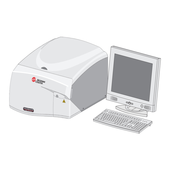
SYSTEM OVERVIEW Figure 1.1 shows the Cell Lab Quanta SC system. The Quanta SC system is a three-color flow cytometer, which provides the additional sizing parameter of Electronic Volume (EV) and the granularity differentiating parameter of Side Scatter. Two light sources are provided; the mercury arc lamp and the 488 nm solid state laser. -
Page 20: Quanta Sc System Overview
USE AND FUNCTION QUANTA SC SYSTEM OVERVIEW QUANTA SC SYSTEM OVERVIEW Figure 1.2 shows the major components of the Quanta instrument. Figure 1.2 Schematic Overview of Quanta Instrument Pre-Amp ECV Vacuum System Flow Cell Vacuum Regulator Vacuum Electrodes Valve Syringe Pump 10 "... -
Page 21: System Components
USE AND FUNCTION SYSTEM COMPONENTS SYSTEM COMPONENTS Figure 1.3 Figure 1.3 System Components Workstation Computer. Workstation Monitor. To control the cytometer and analyze data from Displays data from the Workstation computer. the cytometer. Flow Cytometer. Waste Collection. Contains fluidics, optical flow chamber, Contains Waste bottle and Vacuum bottle for electronics, laser and arc lamp. -
Page 22: Principles Of Operation
USE AND FUNCTION PRINCIPLES OF OPERATION PRINCIPLES OF OPERATION Electronic volume (EV) and optical measurements are made simultaneously in the same spatial location consisting of a flow cell with an equilateral triangular cross section. See Figure 1.4. Figure 1.4 Triangular Flow Cell: Overview This triangular flow geometry produces large hydrodynamic forces that focus the sample stream to the center of the triangular aperture and allows the simultaneous collection of optical and electronic volume measurements. -
Page 23: Warning Labels And Precautions
USE AND FUNCTION WARNING LABELS AND PRECAUTIONS WARNING LABELS AND PRECAUTIONS The Cell Lab Quanta SC system contains a 100-Watt Arc Lamp (Figure 1.5) emitting high intensity heat and a 488 nm diode laser (Figure 1.6). The instrument, therefore, may pose certain hazards associated with this lamp and laser if misused. -
Page 24: Laser
USE AND FUNCTION WARNING LABELS AND PRECAUTIONS Laser The Cell Lab Quanta SC is a Class I laser product. WARNING Avoid direct exposure to the beam. Reflected laser light can be as damaging as the original beam. Remove rings, watchbands, metal pens, pendants and any other reflective accessories from hands and clothing. -
Page 25: Laser Warning Labels
USE AND FUNCTION WARNING LABELS AND PRECAUTIONS Figure 1.6 Laser Warning Labels Figure 1.7 Laser Warning Labels 00000000 CELL LAB QUANTA SC NAME 00000000 100/120/240 VOLTS 4 / 4 / 2 AMPS 50/60 HERTZ SINGLE PHASE Manufactured for Beckman Coutler, inc. by... -
Page 26: Laser Interlocks
USE AND FUNCTION WARNING LABELS AND PRECAUTIONS Laser Interlocks WARNING Risk of personal injury if the laser safety interlock is bypassed. Do not tamper with the laser interlock unless otherwise instructed in this manual. Figure 1.8 shows the laser interlocks. Figure 1.8 Laser Interlocks Top cover interlock... -
Page 27: Handling Precautions
USE AND FUNCTION OPTIONS Handling Precautions Proper handling procedures for samples and reagents used in flow cytometry analysis should be adhered to at all times. Consult appropriate Material Safety Data Sheets for all diluents and reagents used. OPTIONS Hardware Options Figure 1.9 Optical Filter Configuration -- Laser 488 nm PN 721742AD... -
Page 28: Flow Cell Configurations
USE AND FUNCTION OPTIONS Figure 1.10 Optical Filter Configuration -- Lamp 365 nm Flow Cell Configurations Description Configuration Standard 125 x 125 µm 1-10 PN 721742AD... -
Page 29: Jumper Positions For Different Size Particles Μm
USE AND FUNCTION REAGENTS Jumper Positions for Different Size Particles µm Recommended EV Flow Cell Particle Size Jumper Position for different Suggested Aperture µm limits µm Size Particles µm* particles to be analyzed 3-40 15-40 10-15 3-10 Cells, large beads * Sample mean size is depicted in the above table for Electronic Volume (EV) Light Source Configuration Quanta SC Systems configuration contains both light sources, Mercury Arc Lamp and the... -
Page 30: Controls And Indicators
USE AND FUNCTION CONTROLS AND INDICATORS CONTROLS AND INDICATORS For details, see the following illustrations: Figure 1.11, Inside the Instrument: Controls and Indicators Figure 1.12, Vacuum Regulator: Controls and Indicators Figure 1.13, Jumper Positions: Controls and Indicators. Figure 1.11 Inside the Instrument: Controls and Indicators Mercury Arc Lamp voltage display Adjustment dial for Mercury... -
Page 31: Waste Bottle And Vacuum Bottle
USE AND FUNCTION CONTROLS AND INDICATORS Figure 1.13 Jumper Positions: Controls and Indicators Jumper Position S Jumper Position M Jumper Position L Waste Bottle and Vacuum Bottle For details see the following illustrations: Figure 1.14, Reservoirs: Controls and Indicators Figure 1.15, Waste System and Reagents Figure 1.14 Reservoirs: Controls and Indicators Power ON/OFF for pump Fuse... -
Page 32: Workstation Pc: Controls And 5.1 Desktop
USE AND FUNCTION CONTROLS AND INDICATORS Figure 1.15 Waste System and Reagents Waste Bottle Vacuum Bottle Sheath Fluid Bottle Shutdown Solution Bottle Figure 1.16. Figure 1.16 Workstation PC: Controls and Indicators Monitor Keyboard 1.44 Floppy Drive CDRW Drive CD-ROM Read/Write Drive 1-14 PN 721742AD... -
Page 33: Material Safety Data Sheets (Msds)
On the internet, go to http://www.beckmancoulter.com: Select MSDS from the Customer Support drop-down menu. Follow the instructions on the screen Contact your Beckman Coulter Representative if you have difficulty locating the information. If you do not have internet access: In the USA, either call Beckman Coulter Customer Operations (800-526-7694) or write to: Beckman Coulter, Inc. - Page 34 USE AND FUNCTION MATERIAL SAFETY DATA SHEETS (MSDS) 1-16 PN 721742AD...
-
Page 35: Installation
CAUTION Possible instrument damage could occur if you uncrate the instrument, install it, or set it up. Keep the instrument in its packaging until your Beckman Coulter Representative uncrates it for installation and setup. When you receive your instrument, carefully inspect all cartons. If you see signs of mishandling or damage, file a claim with the carrier immediately. -
Page 36: Installation Category
INSTALLATION SPECIAL REQUIREMENTS Table 2.1 System Dimensions and Accessibility Workstation Workstation Specifications Instrument Monitor Computer* Height 44.5 cm (17.5 in.) 43.3 cm (17.1 in.) 43.18 cm (17 in.) Clearance above for servicing 48.3 cm (19 in.) min. Total clearance needed 92.3 cm (36.5 in.) 43.3 cm (17.1 in.) Width... -
Page 37: Electrical Input
INSTALLATION SPECIAL REQUIREMENTS Electrical Input CAUTION Possible instrument damage could occur if you plug the Quanta SC System on the same electrical circuit as another instrument or use an extension cord or a power strip to connect the Quanta SC System. -
Page 38: Drainage
The waste line from the Cytometer is connected to a waste bottle, which sits next to the vacuum module. Dispose of the waste in accordance with your local environmental regulations and acceptable laboratory procedures. INSTALLATION PROCEDURES Your system will be installed by a Beckman Coulter Representative. Interunit Connections Laser Power Supply... -
Page 39: Operation Principles
The Coulter Principle is the reference method for automated cell counting and sizing. SAMPLE FLOW When a sample is placed on the Cell Lab Quanta SC instrument and the button is Start selected, the metering pump aspirates the sample from the sample cup into the sample loop (holding station for the sample). - Page 40 OPERATION PRINCIPLES SAMPLE FLOW Data collection continues until the user manually stops it, a user defined stop criteria is met, or the volume of sample that was aspirated into the sample loop has been dispensed through the flow cell. After a stop criteria is met or the sample volume has been dispensed, several automated post sample processes may occur.
-
Page 41: Specifications
SPECIFICATIONS PERFORMANCE SPECIFICATIONS Absolute Count Table 4.1 Absolute Count Performance Specifications Description Specification Accuracy ± 5% Reproducibility (CV) < 5% Concentration 3 x 10 to 2 x 10 particles per mL. ATTENTION: For greatest accuracy, samples should have a concentration in the range of 2.5 x 10 to 2 x 10 particles per mL. -
Page 42: Parameters
SPECIFICATIONS PERFORMANCE SPECIFICATIONS Parameters Fluorescence 1 Linear/Log display Fluorescence 2 Linear/Log display Fluorescence 3 Linear/Log display Side Scatter Linear/Log display EV Linear display Time display Counts per mL display Calculated Fluorescence Surface Density (FSD)/ Fluorescence Concentration (FC) display Calculated Parameters The following parameters take advantage of the Coulter Volume used in Flow Cytometry: FC –... -
Page 43: Fsd And Fc Calibration
SPECIFICATIONS PERFORMANCE SPECIFICATIONS FC range = 1/EV max channel to FL Max Channel FSD range = 1/(EV max channel)^2/3 to FL Max Channel If EV is 1000 linear channels, and FL is 4 decades of Log then: FC range = .001 to 10000 (7 decades) FSD range = .01 to 10000 (6 decades) FSD and FC Calibration The FSD parameter can be calibrated to Antigen Density assuming that the stain density is... -
Page 44: Installation Requirements
CUPS The Quanta SC System analyzes samples in cups. Beckman Coulter does not recommend the use of one cup in preference to another nor guarantees the acceptability of the sample cup to produce quality results. If you need information on a sample cup not listed here, contact your Beckman Coulter Representative. -
Page 45: Getting Started
Heading 6.1, PERFORM STARTUP for detailed instructions regarding instrument startup. INTRODUCTION TO THE QUANTA SC SOFTWARE Overview Cell Lab Quanta SC software is compatible with Microsoft Windows XP based systems. The Analysis software functions include: Data Collection Instrument Control Data Analysis... -
Page 46: Microsoft Windows Basics
Figure 5.1 Desktop Windows Password The Cell Lab Quanta SC software is password protected and log on specific which protects against unauthorized changes to your data or system. This protection is provided at the application level only and does not apply to the Microsoft Windows XP Operating System (OS). -
Page 47: Launching The Software
Launching the Software You can either launch the software from the Start menu or from your Windows desktop. To Launch from the Start Menu All Programs Cell Lab Quanta SC Cell Lab Quanta SC . The Main screen (Figure 5.2) appears. -
Page 48: Main Screen
GETTING STARTED INTRODUCTION TO THE QUANTA SC SOFTWARE Main Screen When you launch the software, the Main screen (Figure 5.2) appears. The Main menu (Figure 5.3) appears at the top of the screen. For details about the Main screen, see Heading 7.1, UNDERSTANDING THE MAIN SCREEN. -
Page 49: File Menu
GETTING STARTED INTRODUCTION TO THE QUANTA SC SOFTWARE File Information Screen Security Menu Help Menu File Menu When you from the Main menu (Figure 5.4), appears. For details about this menu, File Heading 7.2, WORKING WITH THE FILE MENU. Figure 5.4 File Menu Instrument Menu When you Instrument... -
Page 50: Gain Menu
GETTING STARTED INTRODUCTION TO THE QUANTA SC SOFTWARE Gain Menu When you from the Main menu, Figure 5.6 appears. For details about this menu, see Gain Heading 7.4, WORKING WITH THE GAIN MENU. Figure 5.6 Gain Menu Volume Menu When you Volume from the Main menu, Figure 5.7... -
Page 51: Regions Screen
GETTING STARTED INTRODUCTION TO THE QUANTA SC SOFTWARE Regions Screen When you from the Main menu, Figure 5.9 appears. For details about this menu, Regions Heading 7.7, WORKING WITH THE REGIONS MENU. Figure 5.9 Regions Screen Compensation Screen When you from the Main menu, Figure 5.11 appears. -
Page 52: Protocols Screen
GETTING STARTED INTRODUCTION TO THE QUANTA SC SOFTWARE Protocols Screen When you from the Main menu, Figure 5.11 appears. For details about this Protocols menu, see Heading 7.9, WORKING WITH THE MANAGE PROTOCOLS SCREEN. Figure 5.11 Protocols Screen Current Settings Screen When you Current Instrument Settings from the Main menu,... -
Page 53: File Information Screen
GETTING STARTED INTRODUCTION TO THE QUANTA SC SOFTWARE File Information Screen When you from the Main menu, Figure 5.13 appears. For details about File Information this menu, see Heading 7.11, WORKING WITH THE FILE INFORMATION SCREEN. Figure 5.13 File Information Screen Security Menu When you Security... -
Page 54: Help Menu
GETTING STARTED INTRODUCTION TO THE QUANTA SC SOFTWARE Help Menu When you from the Main menu, Figure 5.15 appears. For details about this menu, Help Heading 7.13, WORKING WITH THE HELP MENU. Figure 5.15 Help Menu Closing a Window or Closing the Software Throughout this manual, you may be instructed to close a software window or to close (shutdown) the Quanta software. -
Page 55: Powering Down The System
GETTING STARTED POWERING DOWN THE SYSTEM POWERING DOWN THE SYSTEM Turn Instrument and Workstation OFF Prior to powering down the system, perform shutdown procedure, see Heading 6.3, PERFORM SHUTDOWN. Close the Quanta software (see Closing the Software.) At the Workstation, Shutdown Shutdown or TURN OFF Allow the system time to shut down. -
Page 56: Placing A Cup On The Instrument
GETTING STARTED PLACING A CUP ON THE INSTRUMENT PLACING A CUP ON THE INSTRUMENT Perform this procedure to place a sample cup securely on the instrument at the sample stage (Figure Sample Stage WARNING Risk of contact with biohazardous material if you use a cup not approved for use on this instrument. - Page 57 GETTING STARTED PLACING A CUP ON THE INSTRUMENT Place the cup on the instrument: Introduce cup so that the probe ) is inserted in the cup. Tilt the cup and push up so that the cup ( ) is secure in the holder.
- Page 58 GETTING STARTED PLACING A CUP ON THE INSTRUMENT 5-14 PN 721742AD...
-
Page 59: Daily Routine
Perform this procedure at the beginning of each day and after switching between light sources or filters. Verify correct filters are installed for the selected application and light source. Power ON the Workstation computer. Launch the Cell Lab Quanta SC software. Once the Quanta software has launched, the following screen appears if a username and password are required. - Page 60 DAILY ROUTINE PERFORM STARTUP Turn ON the Quanta instrument. Next Step . The following screen displays. Follow the directions on the screen to continue with the Start Up Procedure to startup the instrument. For additional information regarding this Start Up step, refer to Heading 10.4, EMPTYING THE WASTE BOTTLE Heading 11.2,...
- Page 61 DAILY ROUTINE PERFORM STARTUP Next Step . The following screen displays. Follow the directions on the screen to continue with the Start Up Procedure to startup the instrument. CAUTION Possible damage to the instrument if Mercury Arc Lamp power starter is continuously depressed after visible light is evident.
-
Page 62: Run Qc (Quality Control) Samples
Follow the directions on the screen to continue with the Start Up Procedure to startup the instrument. RUN QC (QUALITY CONTROL) SAMPLES Beckman Coulter recommends the use of QC materials to gauge instrument performance of reportable parameters. See Chapter 8, QUALITY CONTROL for details. - Page 63 DAILY ROUTINE PERFORM SHUTDOWN Instrument ShutDown. following screen displays. Follow the directions on the screen to continue with the Shut Down Procedure to shutdown the instrument. Refer to Figure 1.14, Reservoirs: Controls and Indicators to locate the appropriate containers. CAUTION Instrument damage can occur if instrument is shut down for more than one (1) day using COULTER Clenz as the...
- Page 64 DAILY ROUTINE PERFORM SHUTDOWN Next Step . The following screen displays. Follow the directions on the screen to continue with the Shut Down Procedure to shutdown the instrument. Refer to Figure 1.14, Reservoirs: Controls and Indicators to locate the appropriate containers and Heading 10.4, EMPTYING THE WASTE BOTTLE for proper waste...
- Page 65 DAILY ROUTINE PERFORM SHUTDOWN Turn OFF the Quanta instrument. PN 721742AD...
- Page 66 DAILY ROUTINE PERFORM SHUTDOWN PN 721742AD...
-
Page 67: Software
SOFTWARE UNDERSTANDING THE MAIN SCREEN The Main screen (Figure 7.1) can display up to ten graphs which may be either single or dual parameter. The seven graph display includes statistics under each graph for its corresponding regions. The X-axis of the first display is always the primary (trigger) parameter. The following parameters are available for collection: FL1 (Fluorescent Channel 1) FL2 (Fluorescent Channel 2) -
Page 68: Main Menu
SOFTWARE UNDERSTANDING THE MAIN SCREEN Main menu (see Figure 5.3) Select a region to be the gate for the display or select All Data Points. If a region is selected from the drop down list, then only data points within that region are shown on the display. -
Page 69: Parameter Information
SOFTWARE UNDERSTANDING THE MAIN SCREEN Recover Sample button allows most of the X-axis is the primary parameter display; sample that was aspirated into the instrument triggers data collection and determines which to be recovered from the sample loop. You can events are collected. -
Page 70: Calibrate Fsd Or Fc
SOFTWARE UNDERSTANDING THE MAIN SCREEN Color drop down list allows the user to select a Log checkbox switches the parameter default color assigned to the histogram data. between linear and logarithmic data collection. IMPORTANT Misleading results can occur if the same color is assigned to parameters and regions. -
Page 71: Region Statistics
SOFTWARE WORKING WITH THE FILE MENU Region drop down list allows the user to select Save button saves your settings and returns a region around the standard to be used for to the Parameter Information dialog. calibration. Cancel button returns you to the Parameter Import button allows the user to import the Information dialog with updating the settings. -
Page 72: Saving Listmode (.Lmd) Files
SOFTWARE WORKING WITH THE FILE MENU Printing Exiting (Closing) the Application Saving Listmode (.LMD) Files Perform this procedure to save the data to the disk as a listmode FCS 2.0 file. File Save Select the desired folder where you want the file to be saved. Type the file name. -
Page 73: Playing Back Files
SOFTWARE WORKING WITH THE FILE MENU File Auto Save Note: When Auto Save is unavailable, it will appear gray in the File Menu. Browse to indicate the location where the files are to be stored. Playing Back Files Perform this procedure to simulate running files that have previously been run. You can also modify the file and re-save it with the new information. -
Page 74: Defining Playback Options
SOFTWARE WORKING WITH THE FILE MENU During file playback, a slider appears on the left of the first histogram that allows you to control the speed of the file playback. Note: Return to normal operation of acquiring data from the instrument by File Normal Mode Defining Playback Options... -
Page 75: Generating A Microsoft Excel Report
SOFTWARE WORKING WITH THE FILE MENU Generating a Microsoft Excel Report Perform this procedure to generate an Excel report based on the currently selected Template file, see Heading 7.10, WORKING WITH THE CURRENT SETTINGS SCREEN. If no Template is selected in the protocol, then one of the Standard Template files will be used based on the number of parameters configured, or you can create a customer Template file. - Page 76 SOFTWARE WORKING WITH THE FILE MENU Select the desired printer and print settings. Print 7-10 PN 721742AD...
-
Page 77: Exiting (Closing) The Application
SOFTWARE WORKING WITH THE INSTRUMENT MENU Exiting (Closing) the Application Perform this procedure to close the application, which automatically sends a Valves Off command to the instrument. File Exit Your Windows desktop appears after the Quanta software is closed. WORKING WITH THE INSTRUMENT MENU The Instrument menu (Figure 5.5) allows you to do the following procedures. -
Page 78: Startup
SOFTWARE WORKING WITH THE INSTRUMENT MENU Start Up Perform this procedure to do a Start Up routine on the instrument. Place an empty sample cup on the instrument. Instrument Start Up Follow the instructions on the screen. Refer to Heading 6.1, PERFORM STARTUP for detailed instructions. -
Page 79: Shutdown
SOFTWARE WORKING WITH THE INSTRUMENT MENU Next Step . The screen will prompt you through the proper procedure to startup the instrument. IMPORTANT Erroneous results can occur if both light systems are active at the same time. Ensure that the appropriate light source is selected during the startup procedure, refer to Heading 6.1, PERFORM STARTUP... -
Page 80: Defining The Power Setting
SOFTWARE WORKING WITH THE INSTRUMENT MENU Defining the Power Setting After the lamp has completed its initial warm up cycle of about 20 minutes, perform this procedure once weekly to define the correct setting for the arc lamp potentiometer located on the power supply next to the voltage display. - Page 81 SOFTWARE WORKING WITH THE INSTRUMENT MENU Type the lamp voltage; notice that the Potentiometer Setting automatically changes. Set the Potentiometer to the new Potentiometer setting value. Record the lamp potentiometer setting in the instrument logbook per your laboratory requirements. 7-15 PN 721742AD...
-
Page 82: Running The Cleaning Cycle
SOFTWARE WORKING WITH THE INSTRUMENT MENU Running the Cleaning Cycle Perform this procedure to remove flow cell clogs. The system runs the cleaning solution through the aperture at a high speed. Place an empty sample cup on the instrument. . The Instrument Cleaning Cycle following screen displays. -
Page 83: Flushing
SOFTWARE WORKING WITH THE INSTRUMENT MENU Next Step . The following screen displays. Follow the directions on the screen to continue with the Cleaning Procedure. Flushing Perform this procedure to empty fluid from the electrodes and certain areas of the flow cell and to refill the locations. -
Page 84: Fill Cup
SOFTWARE WORKING WITH THE INSTRUMENT MENU Instrument Flush (F) Fill Cup Perform this procedure to fill the sample cup with diluent. Place an empty sample cup on the instrument. Instrument Fill Cup Resetting Fluid Count Perform this procedure to reset the fluid count after the sheath bottle has been emptied and re-filled or after the waste container has been emptied to ensure proper level sensor monitoring. -
Page 85: Setting Up The Instrument
SOFTWARE WORKING WITH THE INSTRUMENT MENU Setting Up the Instrument Only your Beckman Coulter Representative can perform this procedure to define the instrument settings. For additional information on the Instrument Setup screen, see Understanding the Instrument Setup Screen. Instrument Instrument Setup This screen is displayed for reference information only. -
Page 86: Understanding The Instrument Setup Screen
SOFTWARE WORKING WITH THE INSTRUMENT MENU Understanding the Instrument Setup Screen Figure 7.5. Figure 7.5 Instrument Setup Screen: Defined Identifies the instrument model Identifies the serial number on back of the instrument Defines the maximum number of Identifies the valve scenario (e.g. Pump) parameters that the instrument can collect used by the instrument Defines the sample volume (about... - Page 87 SOFTWARE WORKING WITH THE INSTRUMENT MENU Defines the syringe size Defines the aperture size Indicates (when checked) that an arc lamp Indicates (when checked) that a laser is is present on the instrument present on the instrument Defines the com port on the PC where the Collect checkbox turns ADC on or off.
-
Page 88: Understanding The Diagnostic Functions Screen
CAUTION Instrument damage can occur if diagnostics functions are attempted by the user without supervision of a Beckman Coulter Representative. Do not attempt to perform these Diagnostic Functions without direction from a Beckman Coulter Representative. This section is used to activate different This section is used to individually verify fluidics functionality. -
Page 89: Laser Control
SOFTWARE WORKING WITH THE INSTRUMENT MENU Laser Control Perform this procedure to adjust the laser power. Instrument Laser Control Understanding the Laser Control Options Figure 7.7. Figure 7.7 Laser Control Options: Defined Scroll bar adjusts the laser power to a Displays the container temperature. -
Page 90: Importing Settings
SOFTWARE WORKING WITH THE INSTRUMENT MENU Importing Settings Perform this procedure to import instrument settings and protocols from other software versions transferred to your instrument. For additional information, see Understanding the Import Settings Screen. Instrument Import Settings Select the desired options: to browse your computer for the desired database file (Quanta.mdb). -
Page 91: Understanding The Import Settings Screen
SOFTWARE WORKING WITH THE INSTRUMENT MENU Understanding the Import Settings Screen Figure 7.8. Figure 7.8 Import Setting Screen: Defined Version/File from which to import Installed versions from which to select Browse to pick a file rather than type in a Cancels unsaved settings. -
Page 92: Understanding The Auto Optical Alignment Screen
SOFTWARE WORKING WITH THE INSTRUMENT MENU Understanding the Auto Optical Alignment Screen Figure 7.9. Figure 7.9 Auto Optical Alignment Screen: Defined Align Using drop down list selects the Count Rate displays the count rate. fluorescence parameter that corresponds to the beads being run. Focus checkbox when enabled adjusts the Position checkbox when enabled adjusts microscope focus when Align button is... -
Page 93: Working With The Gain Menu
SOFTWARE WORKING WITH THE GAIN MENU WORKING WITH THE GAIN MENU For additional information, see Understanding the Tracking Settings Screen. Tracking is the auto gain adjustment done by the computer to keep a known sample in the same channel number. As the Mercury Arc lamp ages, its intensity increases. The effects of the arc lamp’... -
Page 94: Defining Tracking Settings
SOFTWARE WORKING WITH THE GAIN MENU Defining Tracking Settings Perform this procedure to define the tracking settings. Gain Tracking Settings Select the specific parameter tab to modify the tracking settings. the Enable Tracking box. Enter the Narrow Tracking Width and Wide Tracking Width. Save to close dialog box and save your new settings or... -
Page 95: Understanding The Tracking Settings Screen
SOFTWARE WORKING WITH THE GAIN MENU Understanding the Tracking Settings Screen Figure 7.10. Figure 7.10 Tracking Settings Screen: Defined Parameter tabs appear in order defined by Select to cancel your setting changes. the user depending upon the trigger parameter and order set. Enable checkbox to clear the data after the Select to save your setting changes standard is first locked to the correct... -
Page 96: Tracking Start
SOFTWARE WORKING WITH THE GAIN MENU Tracking Start Tracking is the auto gain adjustment performed by the computer to keep a known sample within the same channel number. This adjustment may become necessary as an arc lamp ages and its intensity increases. The effects of arc lamp aging is not usually large; however, tracking may be required for maximum resolution on long sample runs. -
Page 97: Reset Tracking
SOFTWARE WORKING WITH THE VOLUME MENU Reset Tracking Perform this procedure to restore the gain settings to their original values before tracking started. Gain Tracking Reset The Tracking Display on the Main screen is reset when this selection is pressed. WORKING WITH THE VOLUME MENU The Volume menu (Volume... -
Page 98: Calibration Beads
SOFTWARE WORKING WITH THE VOLUME MENU Calibration Beads Dilute the Coulter Calibration beads as follows: Bead µm Part Number Dilution Ratio 1 µm 6602790 1:2000 2 µm 6602792 3 µm 6602793 5 µm 6602794 10 µm 6602796 20 µm 6602798 Place 1 mL of beads in a sample cup. - Page 99 SOFTWARE WORKING WITH THE VOLUME MENU Adjust the lower discriminator to eliminate the noise. Refer to Heading 7.1, UNDERSTANDING THE MAIN SCREEN for detailed instructions. Go to the Regions Menu and set up a Single Parameter Region. Refer to Managing Regions for detailed instructions on setting up this region.
- Page 100 SOFTWARE WORKING WITH THE VOLUME MENU Volume Calibrate Select from the Diameter Calibrate Calibrate Using drop down lists. Insert the diameter assayed value of the beads in the drop down list to the right of Calibrate using list. Refer to the COULTER CC Size Standard reagent package insert for the assay values.
-
Page 101: Understanding The Volume Calibration Screen
SOFTWARE WORKING WITH THE VOLUME MENU Understanding the Volume Calibration Screen Figure 7.11. Figure 7.11 Volume Calibration Screen: Defined Volume/Diameter selection for display Volume/Diameter selection on standard Bead size Import button allows the calibration to be based on a region, the mean of which becomes the Channel Number Drop down list from which to select region Cancels unsaved settings... -
Page 102: Working With The Analysis Menu
SOFTWARE WORKING WITH THE ANALYSIS MENU The instrument resumes normal flow channel display. WORKING WITH THE ANALYSIS MENU The Analysis menu (Figure 5.9) allows you to analyze the Parameter Ratio and Data Flag Settings of each parameter. See: Parameter Ratio Analysis Data Flag Settings Parameter Ratio Analysis Perform this procedure to determine the ratio between any of the parameters from the drop... -
Page 103: Data Flag Settings
SOFTWARE WORKING WITH THE ANALYSIS MENU Data Flag Settings Perform this procedure to specify the region, parameter, and statistic of each data flag. You can assign a lower and upper limit to any statistic that is displayed. If the statistic value falls outside of the limits, it will be highlighted in red on the Main screen and the Excel Report. - Page 104 SOFTWARE WORKING WITH THE ANALYSIS MENU Validation Item Region Parameter from the drop down lists for each flag to be defined. Enter a Minimum and Maximum value. to include the flagging item in the Data Flag Setting list on the right of the window. Note: To set up a flag for Mean Diameter, Mean Surface Area or Mean Cell Volume, you must first...
-
Page 105: Working With The Regions Menu
SOFTWARE WORKING WITH THE REGIONS MENU Show EV Stability to view a graph of the EV Mean Channel versus Time for the most recent run. Note: Fluctuations in the graph can occur if there was a clog or a bubble in the system. WORKING WITH THE REGIONS MENU The Regions menu (Figure... - Page 106 SOFTWARE WORKING WITH THE REGIONS MENU , see Figure 7.13, Single Parameter Region Definition Screen: Defined. Choose the type of region you want to create: Ellipse: An elliptical area of the graph. Polygon: A multi-sided, closed figure. Quadrant: A vertical and a horizontal line, that divides the graph into four (4) areas.
- Page 107 SOFTWARE WORKING WITH THE REGIONS MENU Fill in the Region Order, Region Name, Region Type, Region Color, Gate and select the data source. To create a Single Parameter Gate Region, move the gates using the slider bars located above and below the graph. The graph can be enlarged or reduced by using the up and down arrow buttons on the right hand side of the screen.
-
Page 108: Understanding The Manage Regions Screen
SOFTWARE WORKING WITH THE REGIONS MENU to set the Region and return to the Main screen. Exit Understanding the Manage Regions Screen Figure 7.12. Figure 7.12 Manage Regions Screen: Defined The display order important for color Region name assignment, data source selection Type of region Allows you to select certain data points to be collected and saved. -
Page 109: Single Parameter Region Definition Screen
SOFTWARE WORKING WITH THE REGIONS MENU Parameter for which the region is defined Second parameter for which the region is defined Allows the user to change the region order. Allows the user to change the region The higher order regions will overwrite the order. -
Page 110: Region Definition Screen For And/Or Regions
SOFTWARE WORKING WITH THE REGIONS MENU Region Color allows the user to select a Show Colors checkbox applies the Region color for those data points falling within Color selected from the drop down list. the specified region. Scroll Bars allow the user to adjust the Arrow buttons scale the graph by clicking region’s boundaries. -
Page 111: Showing Region Statistics
SOFTWARE WORKING WITH THE REGIONS MENU Adds Region Definition to list. Double-click Displays all Region Definitions created. a Region Definition to remove from the list. Cancels unsaved settings. Creates a Region Definition. Region to add drop down list allows you to Show Colors checkbox applies the Region select a region to add to the list. -
Page 112: Understanding The Region Statistics Screen
SOFTWARE WORKING WITH THE REGIONS MENU Understanding the Region Statistics Screen Figure 7.15. Figure 7.15 Region Statistics Screen: Defined r Region Number r Count Sequential number assigned by the Number of data points contained in the system. region. r Region Name, Type and Color r Pct Total User-specific information entered by Percent of total counts that are in the... -
Page 113: Working With The Compensation Menu
SOFTWARE WORKING WITH THE COMPENSATION MENU WORKING WITH THE COMPENSATION MENU The Compensation menu (Figure 5.9) allows you to set up compensation and control the display and saving of compensated data. Defining Compensation Settings Perform this procedure to display the compensated data of the sample runs on the screen and to define the compensation settings. - Page 114 SOFTWARE WORKING WITH THE COMPENSATION MENU Run a control stained with the FL1 fluorochrome. Compensation Set FL1 Control. from the Set Compensation Auto dialog displayed to set the correct amount of compensation. Save Repeat steps 4 and 5 for FL2 and FL3. 7-48 PN 721742AD...
- Page 115 SOFTWARE WORKING WITH THE COMPENSATION MENU Display Compensated Data checkbox to show the compensated data on the Main screen. Set. 7-49 PN 721742AD...
-
Page 116: Understanding The Compensation Settings Screen
SOFTWARE WORKING WITH THE COMPENSATION MENU Understanding the Compensation Settings Screen Figure 7.16. Figure 7.16 Compensation Settings Screen: Defined Enable checkbox to display all data Enable checkbox to randomly assign a compensated versus uncompensated. value in the range of 1 to 7 for the data assigned to the zero channel after compensation Enable checkbox to save only the... -
Page 117: Defined,
SOFTWARE WORKING WITH THE COMPENSATION MENU Loads previously saved settings of a Saves current compensation settings to a compensation setting from the list. specified name. Deletes a selected entry from the list. List of Saved Compensation Settings can be loaded, save as new, or deleted. Figure 7.17 Set Compensation using the FLn Control Screen: Defined Axial Compressed Log Transformation Switch Axis button reverses the X- and... -
Page 118: Working With The Manage Protocols Screen
The Manage Protocols screen allows you to use permanent, pre-programmed protocols and to create and save new protocols. Beckman Coulter, Inc. recommends that regular backup copies of your data files and protocols are created on a consistent basis. At this screen, you can perform the following procedures:... -
Page 119: Understanding The Protocol Management Screen
SOFTWARE WORKING WITH THE MANAGE PROTOCOLS SCREEN Understanding the Protocol Management Screen Figure 7.18. Figure 7.18 Protocol Management Screen: Defined Collapse Categories. Expand Categories. Lists the available protocols. Protocol Group drop down list. Lists any descriptive text saved with the Cancels any changes made to the selected protocol. -
Page 120: Loading Protocols
SOFTWARE WORKING WITH THE MANAGE PROTOCOLS SCREEN Loading Protocols Perform this procedure to load an existing protocol. Protocols from the drop down Protocol Group list. Highlight the desired protocol. 7-54 PN 721742AD... -
Page 121: Creating New Protocols
SOFTWARE WORKING WITH THE MANAGE PROTOCOLS SCREEN Creating New Protocols Perform this procedure to create a new protocol with the current settings you are using. Protocols Protocol Group from the drop down list. 7-55 PN 721742AD... - Page 122 SOFTWARE WORKING WITH THE MANAGE PROTOCOLS SCREEN Name the new protocol: Type the protocol name (e.g. June 30 04). Choose the Category from the drop down list or type new category name. appears. . The protocol name appears in the protocol list. 7-56 PN 721742AD...
-
Page 123: Saving Current Settings To A Protocol
SOFTWARE WORKING WITH THE MANAGE PROTOCOLS SCREEN Saving Current Settings to a Protocol Perform this procedure to save the instrument’ s current settings to a previously created protocol that you or another user created. Default protocols provided with the system cannot be changed. -
Page 124: Deleting Protocols
SOFTWARE WORKING WITH THE MANAGE PROTOCOLS SCREEN Deleting Protocols Perform this procedure to delete a protocol. Protocols Protocol Group from the drop down list. 7-58 PN 721742AD... - Page 125 SOFTWARE WORKING WITH THE MANAGE PROTOCOLS SCREEN Highlight the desired protocol to be deleted. Note: You cannot delete system protocols; you can only delete protocols that you or another user created. 7-59 PN 721742AD...
-
Page 126: Save Description Changes (Editing A Protocol)
SOFTWARE WORKING WITH THE MANAGE PROTOCOLS SCREEN Save Description Changes (Editing a Protocol) Once you have selected a protocol, you can Perform this procedure to create a new protocol or edit the protocol description, except for default protocols which are LOCKED and cannot be changed. -
Page 127: Create/Delete Protocol Groups
SOFTWARE WORKING WITH THE MANAGE PROTOCOLS SCREEN Type in new description text. Create/Delete Protocol Groups Perform this procedure to create or delete a Protocol Group. When working with protocols, a user can only load or save protocols from the Protocol Group they are assigned. -
Page 128: Assign A User To A Protocol Group
SOFTWARE WORKING WITH THE MANAGE PROTOCOLS SCREEN and enter a name for the new Protocol Group. Highlight the Protocol Group to delete Delete. Assign a User to a Protocol Group Perform this procedure to assign a user to a Protocol Group. One or more users can be assigned to a Protocol Group. -
Page 129: Remove A User Assigned To A Protocol Group
SOFTWARE WORKING WITH THE MANAGE PROTOCOLS SCREEN on the Protocol Group in the All Protocol Groups window to complete assigning the current user to this protocol group. Remove a User Assigned to a Protocol Group Security Manage Users. Note: The Security list displays only if the 21 CFR Option is installed;... -
Page 130: 7.10 Working With The Current Settings Screen
SOFTWARE WORKING WITH THE CURRENT SETTINGS SCREEN 7.10 WORKING WITH THE CURRENT SETTINGS SCREEN When you select from the Main menu, the Current Setting screen Current Settings (Figure 5.12) appears. This screen allows you to define many settings as defined in the following procedures. -
Page 131: Defining The Concentration (Use, # Of Seconds, And Start Time)
SOFTWARE WORKING WITH THE CURRENT SETTINGS SCREEN Defining the Concentration (Use, # of Seconds, and Start Time) Perform this procedure to set the concentration to be collected, to define the # of seconds for sample collection and to define when the concentration is to begin collection. Current Settings Define the Concentration settings Enabling/Disabling Checkboxes... -
Page 132: Defining Auto Save Options
SOFTWARE WORKING WITH THE CURRENT SETTINGS SCREEN Current Settings Enable/disable checkboxes: To enable, until. appears. To disable, until appears. Defining Auto Save Options Perform this procedure to define the following Auto Save options: automatically saves the results of each run to a pre-selected Auto Save File to Directory directory. - Page 133 SOFTWARE WORKING WITH THE CURRENT SETTINGS SCREEN ATTENTION: If you select Auto Rinse , you must remove the sample immediately after data collection is complete or the sample will be destroyed. Auto Recover Sample automatically recovers the remaining portion of the aspirated sample for use during another run.
-
Page 134: Customizing An Excel Report
SOFTWARE WORKING WITH THE CURRENT SETTINGS SCREEN Customizing an Excel Report Pre-defined Excel Templates If you do not define an Excel template, the system will automatically select a pre-defined template. Template Name # of Graphs 1DTemplate.xls one (1) 3DTemplate.xls three (3) 5DTemplate.xls five (5) 7DTemplate.xls... - Page 135 SOFTWARE WORKING WITH THE CURRENT SETTINGS SCREEN The selected Excel template is opened and a list of report items is displayed. IMPORTANT Misleading results can occur. When creating an Excel Report template, include unique identifiers, such as filename, sample ID, instrument serial number, and date and time of analysis.
-
Page 136: Defining Filter Configurations
SOFTWARE WORKING WITH THE CURRENT SETTINGS SCREEN The new report template is automatically saved when the dialog box is closed. Defining Filter Configurations Perform this procedure to enter the following information regarding the specific filters used on your instrument: Arc Lamp Excitation Filter allows you to enter the filter name/description. -
Page 137: Understanding The Current Instrument Settings Screen
SOFTWARE WORKING WITH THE CURRENT SETTINGS SCREEN Understanding the Current Instrument Settings Screen Figure 7.19. Figure 7.19 Current Instrument Settings Screen: Defined Stop Sample Criteria. Concentration. r Total Count stops the sample run when r Use enabled checkbox indicates the number of particles collected either concentration is to be collected. - Page 138 SOFTWARE WORKING WITH THE CURRENT SETTINGS SCREEN r Time (Min:Sec) stops the sample when the given time is counted from the end of Stabilization has elapsed. If 0:0 is set as the value, then the system ignores the Stop time. r Concentration Value stops the sample run when the concentration value is met.
-
Page 139: 7.11 Working With The File Information Screen
SOFTWARE WORKING WITH THE FILE INFORMATION SCREEN Sets the selected instrument settings. Filter Configuration. r Allows user to input the specific filters being used in the instrument. t FL1/SS-FL2/FL3 Dichroic t FL1-SS Dichroic t FL2-FL3 Dichroic t FL1 Emission Filter t FL2 Emission Filter t FL3 Emission Filter Filter Configuration. -
Page 140: Entering Sample Information
SOFTWARE WORKING WITH THE FILE INFORMATION SCREEN Entering Sample Information Perform this procedure to enter information for a specific sample. File Information Enter the file information for your sample. 7-74 PN 721742AD... -
Page 141: Understanding The File Information Screen
SOFTWARE WORKING WITH THE FILE INFORMATION SCREEN Understanding the File Information Screen Figure 7.20. Figure 7.20 File Information Screen: Defined File Name allows you to name the file Date automatically displays the current system date; this date is populated by the Quanta SC system. -
Page 142: 7.12 Working With The Security Menu
SOFTWARE WORKING WITH THE SECURITY MENU Operator allows you to enter the name or Patient/Sample Description allows you to ID of the operator who is running this enter a description for the patient/sample sample 1& Tissue Type allows you to define the type Sample ID allows you to assign a specific of tissue for the sample Sample ID... -
Page 143: Manage Users
SOFTWARE WORKING WITH THE SECURITY MENU Manage Users Perform this procedure to manage users and their security rights. Security Manage Users. Select a user from the list to change the security settings for that username. Security Settings include: Security Rights User Protocol Groups All Protocol Groups, and Password Options. -
Page 144: Understanding The Security Menu Screen
SOFTWARE WORKING WITH THE SECURITY MENU Understanding the Security Menu Screen Figure 7.21. Figure 7.21 Security Menu: Manage Users List of users established for the Quanta SC Security Rights checkboxes allows the system. system administrator to choose which rights are to be associated with a given username. Sign on field displays username. -
Page 145: Password Options
SOFTWARE WORKING WITH THE SECURITY MENU Password Options Perform this procedure to set the password security options. Security Password Options Set the password security options according to your laboratory’ s requirements. Options include: Auto Log on as Admin bypasses the log in screen and access protections Remember last user requires username to be typed or selected from drop down list Require alpha/numeric password Minimum password length... -
Page 146: 7.13 Working With The Help Menu
SOFTWARE WORKING WITH THE HELP MENU directory on some computers. Please contact your Windows Administrator to provide the proper read/write permissions for users. Security Modify Database Path. 7.13 WORKING WITH THE HELP MENU The Help menu (Figure 5.15) has two options: , which launches the online Help file (see Launching Help) -
Page 147: Quality Control
DAILY QC Beckman Coulter recommends the use of QC materials to gauge instrument performance of reportable parameters. Daily QC depends on the light source and application that will be run that day. -
Page 148: Running Flow-Check Fluorospheres
QUALITY CONTROL DAILY QC Running Flow-Check Fluorospheres Prepare the Flow-Check Fluorospheres according to package insert instructions, refer to Heading 8.4, QC METHOD for mixing and handling of fluorospheres. Load the Laser Alignment protocol. Ensure sample is properly mixed prior to placing a sample cup on the instrument. Start from the Main screen. -
Page 149: Running The Arc Lamp Alignment Beads
QUALITY CONTROL DAILY QC If the HPCVs are greater than 3%, perform the AUTOMATICALLY ALIGNING THE OPTICS found in Heading 8.5. Running the Arc Lamp Alignment Beads Prepare the beads as required for your application, refer to Heading 8.4, QC METHOD. -
Page 150: Qc Method
QUALITY CONTROL QC METHOD If the HPCVs are greater than 3%, perform the AUTOMATICALLY ALIGNING THE OPTICS found in Heading 8.5. QC METHOD Prepare QC Material Flow-Check Fluorospheres Prepare Flow-Check Fluorospheres according to the package insert instructions. Follow the package insert instructions for mixing and handling fluorospheres. Check that the values for Mean, and the half-peak coefficient of variation (HPCV) for FL1, FL2 and FL3 are within your laboratory's acceptance limits and record them in a logbook. - Page 151 QUALITY CONTROL AUTOMATICALLY ALIGNING THE OPTICS Prepare the required QC materials, refer to Heading 8.3, DAILY QC for detailed instructions Load the Optical Alignment protocol, refer to Loading Protocols in Chapter 7 of the Quanta SC manual. Place an empty sample cup on the instrument.
- Page 152 QUALITY CONTROL AUTOMATICALLY ALIGNING THE OPTICS Auto Optical Alignment from the Instrument Menu. Select the fluorescence parameter (FL1, FL2, or FL3) that corresponds to the application being run. Select one of the following options: Focus: Adjusts Microscope Focus Position: Adjusts Microscope Position Lamp X: Adjusts Lamp X-axis (arc lamp only)
- Page 153 QUALITY CONTROL AUTOMATICALLY ALIGNING THE OPTICS When HPCVs are less than 3%, Exit. Place an empty sample cup on the instrument and perform a Rinse Main to return to the Main Screen. PN 721742AD...
- Page 154 QUALITY CONTROL AUTOMATICALLY ALIGNING THE OPTICS PN 721742AD...
-
Page 155: Sample Analysis
SAMPLE ANALYSIS BEFORE RUNNING SAMPLES Verify correct filters are installed and correct protocols are loaded for the selected application and light source. If the instrument has been idle for more than one hour with an empty sample cup, press from the Main Screen. The instrument performs a rinse cycle and primes for RINSE presentation of the next sample. -
Page 156: Running Samples
SAMPLE ANALYSIS RUNNING SAMPLES RUNNING SAMPLES IMPORTANT Risk of sample misidentification if a power failure occurs during sample processing. In the event of a power failure, discard any in-process samples. Available applications are provided as application notes and are separate from this manual. Analyze the sample according to the instructions for the specific protocol that you are following. - Page 157 SAMPLE ANALYSIS RUNNING SAMPLES To resume sample flow and data collection, press the Resume button. IMPORTANT Possible erroneous results can occur if the sample has stopped and you press Resume or Continue during sample processing. Sample settling can occur in the tubing; the amount of settling will depend upon the type of sample and the length of time the sample has been stopped.
-
Page 158: After Running Samples
SAMPLE ANALYSIS AFTER RUNNING SAMPLES AFTER RUNNING SAMPLES After the sample has been run, you can recover sample from the sample loop. Press Recover Sample on the Main screen. Recovery occurs even if the run volume selected has been completely dispensed through the flow cell because extra volume is aspirated during the sample “Aspirating”... -
Page 159: Setting Initial Gain, Voltage And Discriminator Values
SAMPLE ANALYSIS SETTING INITIAL GAIN, VOLTAGE AND DISCRIMINATOR VALUES Slightly tilt the sample cup to release the vacuum seal, then gently pull the cup down Check the Waste Bottle to determine if it needs to be emptied. If so, do Heading 10.4, EMPTYING THE WASTE BOTTLE. - Page 160 SAMPLE ANALYSIS WORKING WITH REGIONS PN 721742AD...
-
Page 161: Cleaning/Replacement
CLEANING/REPLACEMENT 10.1 INSTRUMENT CLEANING AND HANDLING REQUIREMENTS CAUTION Risk of damage to the instrument if any fluid comes into contact with the electronic components. To prevent damage to the instrument, do not let any fluid come into contact with the internal instrument components. -
Page 162: 10.3 Opening/Closing The Cover
CLEANING/REPLACEMENT OPENING/CLOSING THE COVER 10.3 OPENING/CLOSING THE COVER Certain maintenance, replacement or troubleshooting procedures may require the instrument cover to be opened. Pull front cover open from the right side of instrument. Pull top of cover up until it locks in the upright position. - Page 163 CLEANING/REPLACEMENT OPENING/CLOSING THE COVER To close the cover properly, reverse the above steps pulling the top cover down first and then closing the front cover. CAUTION Closing the front cover before the top cover can damage the covers and interrupt the laser interlock.
-
Page 164: 10.4 Emptying The Waste Bottle
CLEANING/REPLACEMENT EMPTYING THE WASTE BOTTLE 10.4 EMPTYING THE WASTE BOTTLE WARNING Risk of biohazardous contamination if you have skin contact with the waste and vacuum bottles, their contents, and associated tubing. The waste and vacuum bottles and associated tubing might contain residual biological material and must be handled with care. -
Page 165: 10.5 Changing A Filter
CLEANING/REPLACEMENT CHANGING A FILTER 10.5 CHANGING A FILTER Perform Shutdown, refer to Heading 6.3, PERFORM SHUTDOWN for detailed instructions. Open the cover, refer to Heading 10.3, OPENING/CLOSING THE COVER detailed instructions. a c t a c t Locate filter area. 10-5 PN 721742AD... - Page 166 CLEANING/REPLACEMENT CHANGING A FILTER Loosen thumbscrews and lift off filter cover. Use a 3/16 in. Allen wrench to unscrew the bolt in the middle of the optical filter plate. 10-6 PN 721742AD...
- Page 167 CLEANING/REPLACEMENT CHANGING A FILTER Lift the optical filter plate up and off. Set this optical filter aside. Note: Do not touch lens. Inspect lens to ensure free from smudges or debris. If smudges are present, clean with lens cloth. Turn the optical filter on its side and locate the screw that holds the filter holder to be removed.
- Page 168 CLEANING/REPLACEMENT CHANGING A FILTER Use a 9/64 in. Allen wrench to remove the screw that holds the filter to be replaced from the optical filter plate. Note: Do not touch lens. Inspect lens to ensure free from smudges or debris. If smudges are present, clean with lens cloth.
- Page 169 CLEANING/REPLACEMENT CHANGING A FILTER FL1 Filter and holder (525 BP) For Mercury Arc Lamp (465 BP) FL2 Filter and holder (575 BP) FL3 Filter and holder (670 LP) Dichroic/Splitter and holder (600 DLP) Dichroic/Splitter and holder (550 DLP) Dichroic/Splitter and holder (Z488RDC) For Mercury Arc Lamp, this filter is not used.
- Page 170 CLEANING/REPLACEMENT CHANGING A FILTER Insert the filter holder into the optical filter plate and screw in the holding screw. Replace the optical filter plate into the instrument. Check that it is firmly seated. Pins 10-10 PN 721742AD...
- Page 171 CLEANING/REPLACEMENT CHANGING A FILTER Use a 3/16 in. Allen wrench to screw in the bolt in the middle of the optical filter plate. Replace filter cover and tighten thumbscrews. 10-11 PN 721742AD...
-
Page 172: 10.6 Changing An Arc Lamp Excitation Filter
CLEANING/REPLACEMENT CHANGING AN ARC LAMP EXCITATION FILTER Close the cover. CAUTION Closing the front cover before the top cover can damage the covers and interrupt the laser interlock. Pull the top cover down first, then close the front cover. a c t Perform Startup, refer to Heading 6.1, PERFORM STARTUP for detailed instructions. - Page 173 CLEANING/REPLACEMENT CHANGING AN ARC LAMP EXCITATION FILTER Open the cover, refer to Heading 10.3, OPENING/CLOSING THE COVER detailed instructions. a c t a c t Locate filter area. 10-13 PN 721742AD...
- Page 174 CLEANING/REPLACEMENT CHANGING AN ARC LAMP EXCITATION FILTER Place selected Arc Lamp Excitation Filter in front of the Mercury Arc Lamp. Close the cover. CAUTION Closing the front cover before the top cover can damage the covers and interrupt the laser interlock. Pull the top cover down first, then close the front cover.
-
Page 175: 10.7 Replacing The Fuse
CLEANING/REPLACEMENT REPLACING THE FUSE 10.7 REPLACING THE FUSE Perform this procedure to replace a blown fuse. Prior to beginning this procedure, ensure that the power cord has been disconnected from the instrument, for details refer to Heading 10.2, INSTRUMENT QUICK DISCONNECT. - Page 176 CLEANING/REPLACEMENT REPLACING THE FUSE Using a flat head screwdriver, open the fuse holder door by inserting in notch at the top of the holder. Remove fuse to be replaced from the fuse holder. Insert new fuse into holder. 10-16 PN 721742AD...
-
Page 177: 10.8 Adjusting Fuse Voltage
CLEANING/REPLACEMENT ADJUSTING FUSE VOLTAGE Replace fuse holder into the fuse module. Replace fuse holder door and reconnect power to the instrument. 10.8 ADJUSTING FUSE VOLTAGE Perform this procedure to adjust or change the fuse voltage for those countries operating outside of the 120 V AC. Prior to beginning this procedure, ensure that the power cord has been disconnected from the instrument, for details refer to Heading 10.2, INSTRUMENT QUICK... - Page 178 CLEANING/REPLACEMENT ADJUSTING FUSE VOLTAGE Using a flat head screwdriver, open the fuse holder door by inserting in notch at the top of the holder. 10-18 PN 721742AD...
- Page 179 CLEANING/REPLACEMENT ADJUSTING FUSE VOLTAGE Pull the voltage indicator out of the fuse holder. Turn the voltage indicator to the appropriate voltage rate. Reinsert the voltage indicator in the fuse holder ensuring the correct voltage is displayed through the fuse holder window.
- Page 180 CLEANING/REPLACEMENT ADJUSTING FUSE VOLTAGE Replace fuse holder door and reconnect power to the instrument. 10-20 PN 721742AD...
-
Page 181: Troubleshooting
TROUBLESHOOTING 11.1 SYSTEM CONNECTIONS There system is connected: from the PC to the instrument, monitor, and printer from the Analyzer to the Waste and Vacuum Bottles For details regarding these connections, see: Figure 11.1, Cable Connections: Back of Instrument Figure 11.2, Cable Connections: Back of PC Figure 11.3, Cable Connections: Monitor Figure 11.4, Tubing Connections: Waste Bottle and Vacuum Bottle Figure 11.1 Cable Connections: Back of Instrument... - Page 182 TROUBLESHOOTING SYSTEM CONNECTIONS Figure 11.2 Cable Connections: Back of PC Power ON/OFF switch Power cord, plugs into the surge protector Keyboard connection Mouse connection Printer/USB Pump Printer Port (only) Monitor Laser Motors Valves Figure 11.3 Cable Connections: Monitor Power cord, plugs into the surge protector Cable, connects to the PC 11-2...
-
Page 183: 11.2 Monitor Vacuum Readings
TROUBLESHOOTING MONITOR VACUUM READINGS Figure 11.4 Tubing Connections: Waste Bottle and Vacuum Bottle Tubing connection to pump Tubing connection to vacuum to instrument Tubing connection connects waste to vacuum bottles Tubing connection to waste from instrument 11.2 MONITOR VACUUM READINGS The vacuum monitoring occurs as part of the Start Up procedure. -
Page 184: 11.3 Error Messages
TROUBLESHOOTING ERROR MESSAGES 11.3 ERROR MESSAGES Table 11.1. Table 11.1 Error Messages Message Probable Cause Recommended Corrective Action Metering Pump communications Cable is not plugged in, or not Check the cable, power. error working properly. The power is off. Metering Pump error Hardware Failure with the pump. -
Page 185: 11.4 Troubleshooting Guide
TROUBLESHOOTING TROUBLESHOOTING GUIDE 11.4 TROUBLESHOOTING GUIDE Table 11.2 provides a troubleshooting guide. Table 11.2 Troubleshooting Guide Problem Area Situation Suggested Action Analysis If the instrument stays at Press Stabilizing button to end “Stabilizing” for more than 10 the stabilization process and to seconds: begin normal data collection. -
Page 186: Troubleshooting Guide
TROUBLESHOOTING TROUBLESHOOTING GUIDE Table 11.2 Troubleshooting Guide (Continued) Problem Area Situation Suggested Action Performance If performance problems occur For all performance problems, due to: perform Flush twice and then a Cleaning Cycle. If performance r Bubbles in tubings and erratic problems still persist: flow rate r HPCV out of limits, perform... - Page 187 REFERENCES Coulter WH. High speed automatic blood cell counter and cell size analyzer. Paper presented at National Electronics Conference, Chicago, IL, 1956; October 3. Thomas, Richard A. et. al., NASA/American Cancer Society High-Resolution Flow Cytometry Project I, Cytometry 43-2-11 (2001). Wen, Jinghai et.
- Page 188 REFERENCES 16. DNA Cell Cycle Analysis with 4’, 6-Diamidino-2Phenylindole (DAPI) or Propidium Iodide (PI) Nuclear Stains, PN A-2012A 17. Evaluation of Cellular Viability with Propidium Iodide or 7-Amino-Actinomycin D, PN A-2013A. 18. Evaluation of Apoptosis with Annexin V and Propidium Iodide or 7-Amino-Actinomycin D, PN A-2014A 19.
-
Page 189: Glossary,
GLOSSARY Accuracy - The ability of an instrument to agree with a predetermined reference value at any point within the operating range. Contrast with precision. APC - Abbreviation for allophycocyanin dye. Arc lamp alignment beads - Mercury Arc Lamp alignment is obtained by using these beads to insure proper alignment, optimal resolution and sensitivity with the systems optics. - Page 190 GLOSSARY dc - Abbreviation for direct current. Defaults - Original settings for the instrument. You can change them to customize the settings for your laboratory. DiOC5(3) - Abbreviation for oxacarbocyanine dye. Discriminator - A channel setting for a parameter that lets you ignore events below the setting.
- Page 191 GLOSSARY Forward scatter (FS) - The laser light scattered at narrow angles to the axis of the laser beam. The amount of forward scatter is proportional to the size of the cell that scattered the laser light. Forward scatter (FS) sensor - Collects the forward scatter and generates voltage pulse signals.
- Page 192 GLOSSARY Microscope focus - Accurately adjusts the beam of light directly at the cells/particles in the flow stream which will then provide optimal resolution. Mouse - A pointing device. The cursor on the Workstation screen moves as you slide the mouse on your desk or other flat surface.
- Page 193 GLOSSARY Sensitivity - The ability of the instrument to distinguish very low levels of light scatter and fluorescence from background light or electronic noise. Sheath fluid - A balanced electrolyte solution. Side scatter - The amount of laser light scattered at about a 90° angle to the axis of the laser beam.
- Page 194 GLOSSARY GLOSSARY-6 PN 721742AD...
- Page 195 INDEX Numerics coefficient of variation (CV) See CV 21 CFR Part 11 Option color compensation Create/Delete Protocol Groups, 7-63 definition, GLOSSARY-1 container waste, capacity, controls accessibility, instrument and indicators, definition, GLOSSARY-1 installation requirements, and indicators, instrument, 1-12 accuracy definition, GLOSSARY-1 definition, GLOSSARY-1 running Flow-Check fluorospheres,...
- Page 196 INDEX electronic volume sensor, definition, GLOSSARY-3 definition, GLOSSARY-2 events definition, GLOSSARY-2 definition, GLOSSARY-2 export file definition, GLOSSARY-2 gain extension cord definition, GLOSSARY-3 Caution, gating definition, GLOSSARY-3 definition, GLOSSARY-3 definition, GLOSSARY-2 graphics for illustration only, xvii definition, GLOSSARY-2 ground path requirement, definition, GLOSSARY-2 file...
- Page 197 INDEX space needed, unpacking, optical alignment integral signal definition, GLOSSARY-4 definition, GLOSSARY-3 See also signals package inserts contain fluorospheres laser instructions, 8-2, definition, GLOSSARY-3 use to establish expected ranges, linear amplification parameter ratio analysis See gain definition, GLOSSARY-4 listmode data, definition, GLOSSARY-3 definition, GLOSSARY-4...
- Page 198 INDEX requirements, installation instrument accessibility, ventilation requirements, space needed, voltage pulse signals room temperature definition, GLOSSARY-5 ambient operating, special requirements, specifications, running waste Flow-Check fluorospheres, disposal, requirements, waste container capacity, sample window how to handle after power failure, See pop-up window risk of misidentification, Workstation sample cup...
-
Page 199: Beckman Coulter, Inc. Customer End User License Agreement
BECKMAN COULTER, INC. CUSTOMER END USER LICENSE AGREEMENT This Product contains software that is owned by Beckman Coulter, Inc. or its suppliers and is protected by United States and international copyright laws and international trade provisions. You must treat the software contained in this Product like any other copyrighted material. - Page 201 TRADEMARKS BECKMAN COULTER and the stylized logo are trademarks of Beckman Coulter Inc., and are registered in the USPTO. All other trademarks, service marks, products, or services are trademarks or registered trademarks of their respective holders. PN 721742AD...
- Page 202 Started • Daily Routine • Quality Control • Sample Analysis • Data Review • PN 721742 Maintenance • Troubleshooting • References • Index Come visit us at www.beckmancoulter.com Printed on Recycled Paper Copyright © Beckman Coulter, Inc. 1999-2011 All Rights Reserved...
Need help?
Do you have a question about the Cell Lab Quanta SC and is the answer not in the manual?
Questions and answers