Table of Contents
Advertisement
Advertisement
Table of Contents

Related Manuals for Vega VEGAFLEX 61


Summary of Contents for Vega VEGAFLEX 61
-
Page 1: Operating Instructions
Operating Instructions VEGAFLEX 61 Profibus PA Document ID: 31835 Guided Microwave... -
Page 2: Table Of Contents
Parameter adjustment with PDM ....36 Saving the parameter adjustment data ... . 36 VEGAFLEX 61 • Profibus PA... - Page 3 You can find them listed in chapter "Product description". Instructions manuals for accessories and replacement parts Tip: To ensure reliable setup and operation of your VEGAFLEX 61, we offer accessories and replacement parts. The corresponding doc- umentations are: 27720 - VEGADIS 61...
-
Page 4: About This Document
This symbol indicates special instructions for Ex applications. List The dot set in front indicates a list with no implied sequence. à Action This arrow indicates a single action. Sequence Numbers set in front indicate successive steps in a procedure. VEGAFLEX 61 • Profibus PA... -
Page 5: For Your Safety
During work on and with the device the required personal protective equipment must always be worn. 2.2 Appropriate use VEGAFLEX 61 is a sensor for continuous level measurement. You can find detailed information on the application range in chapter "Product description". -
Page 6: Safety Label On The Instrument
2.6 CE conformity This device fulfills the legal requirements of the applicable EC guidelines. By attaching the CE mark, VEGA provides a confirmation of successful testing. You can find the CE conformity declaration in the download area of www.vega.com. -
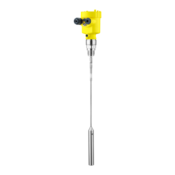
Page 7: Product Description
Process fitting with probe Housing with electronics Housing cover, optionally available with indicating and adjustment module Fig. 1: VEGAFLEX 61 in cable version with plastic housing Housing cover with integrated indicating and adjustment module (optional) Housing with electronics Process fitting Type label The type label contains the most important data for identification and... -
Page 8: Principle Of Operation
In addition to the type label outside, you can also find the serial number on the inside of the instrument. 3.2 Principle of operation VEGAFLEX 61 is a level sensor with cable or rod probe for continuous Application area level measurement. -
Page 9: Packaging, Transport And Storage
3 Product description with the suitable VEGA DTM in conjunction with an adjustment software according to the FDT/DTM standard, e.g. PACTware and with the adjustment program PDM 3.4 Packaging, transport and storage Packaging Your instrument was protected by packaging during transport. Its capacity to handle normal loads during transport is assured by a test according to DIN EN 24180. -
Page 10: Mounting
Rain and condensation water can thus drain off. This applies mainly to outdoor mounting as well as installation in areas where high humidity is expected (e.g. through cleaning processes) or on cooled or heated vessels. VEGAFLEX 61 • Profibus PA... -
Page 11: Mounting Instructions
The max. permissible pressure is specified in chapter "Technical data" or on the type label of the sensor. 4.2 Mounting instructions Mount VEGAFLEX 61 in such a way that the distance to vessel Mounting position installations or to the vessel wall is at least 300 mm (12 in). - Page 12 When installing rod or cable probes without metal vessel wall, e.g. in plastic vessels, the measured value can be influenced by strong electromagnetic fields (emitted interference according to EN 61326: class A). In this case, use a probe in coax version. VEGAFLEX 61 • Profibus PA...
- Page 13 Flange Metal sheet Concrete vessel When installed in thick concrete ceilings, VEGAFLEX 61 should be mounted front flush to the lower edge. In concrete silos, the distance to the wall should be at least 500 mm (20 in). ø >160 mm (ø...
- Page 14 £ 100 Fig. 6: Mounting socket When welding the socket, make sure that the socket is flush to the vessel wall. Fig. 7: Socket must be installed flush Unfavourable installation Socket flush - optimum installation VEGAFLEX 61 • Profibus PA...
- Page 15 Measuring probes can be mounted in bypass tubes up to DN 200. If VEGAFLEX 61 is used in standpipes or bypass tubes, contact with the tube wall should be avoided. We offer spacers as accessories for fastening the probe in the middle of the tube.
- Page 16 4 Mounting Inflowing medium Make sure that the probe is not subjected to strong lateral forces. Mount VEGAFLEX 61 at a position in the vessel where no disturbances, e.g. from filling openings, agitators, etc., can occur. Fig. 9: Lateral load...
-
Page 17: Connecting To Power Supply
If overvoltage surges are expected, overvoltage arresters should be installed according to Profibus specifications Tip: We recommend VEGA overvoltage arrester B63-32. In hazardous areas you should take note of the appropriate regulations, conformity and type approval certificates of the sensors and power supply units. -
Page 18: Connection Procedure
1 cm (0.4 in) of insulation from the ends of the individual wires Insert the cable into the sensor through the cable entry Lift the opening levers of the terminals with a screwdriver (see following illustration) VEGAFLEX 61 • Profibus PA... -
Page 19: Wiring Plan, Single Chamber Housing
12 Screw the housing cover on The electrical connection is finished. 5.3 Wiring plan, single chamber housing The following illustrations apply to the non-Ex as well as to the Ex-ia version. VEGAFLEX 61 • Profibus PA... -
Page 20: Wiring Plan, Double Chamber Housing
Wiring plan Display I 2 C Fig. 12: Wiring plan, single chamber housing Voltage supply/Signal output 5.4 Wiring plan, double chamber housing The following illustrations apply to the non-Ex as well as to the Ex-ia version. VEGAFLEX 61 • Profibus PA... - Page 21 Terminals for VEGADIS 61 Connection compart- ment I ² C Fig. 14: Connection compartment, double chamber housing Plug connector for VEGACONNECT (I²C interface) Ground terminal for connection of the cable screen Spring-loaded terminals for voltage supply VEGAFLEX 61 • Profibus PA...
-
Page 22: Wiring Plan - Version Ip 66/Ip 68, 1 Bar
5.5 Wiring plan - version IP 66/IP 68, 1 bar Wire assignment con- nection cable Fig. 16: Wire assignment connection cable brown (+) and blue (-) to power supply or to the processing system Shielding VEGAFLEX 61 • Profibus PA... -
Page 23: Set Up With The Indicating And Adjustment Module Plicscom
Screw housing cover with inspection window tightly back on Removal is carried out in reverse order. The indicating and adjustment module is powered by the sensor, an additional connection is not necessary. VEGAFLEX 61 • Profibus PA... - Page 24 Fig. 17: Insert indicating and adjustment module Note: If you intend to retrofit the instrument with an indicating and adjustment module for continuous measured value indication, a higher cover with an inspection glass is required. VEGAFLEX 61 • Profibus PA...
-
Page 25: Adjustment System
The functions of the individual keys are shown in the above illustration. Approx. 10 minutes after the last pressing of a key, an automatic reset to measured value indication is triggered. Any values not confirmed with [OK] will not be saved. VEGAFLEX 61 • Profibus PA... -
Page 26: Setup Steps
6 Set up with the indicating and adjustment module PLICSCOM 6.4 Setup steps After VEGAFLEX 61 is connected to voltage supply or after voltage Switch on phase recurrence, the instrument carries out a self-check for approx. 30 seconds. The following steps are carried out: Internal check of the electronics Indication of the instrument type, the firmware as well as the... - Page 27 Enter the appropriate distance value in m (corresponding to the percentage value) for the full vessel. Keep in mind that the max. level must lie below the dead band. Save the settings with [OK]. VEGAFLEX 61 • Profibus PA...
- Page 28 If the volume should not be displayed in percent but e.g. in l or kg, a scaling can be also set in the menu item "Display". VEGAFLEX 61 • Profibus PA...
- Page 29 [->] key. Caution: Note the following, if VEGAFLEX 61 is used as part of an overfill protection system according to WHG: If a linearisation curve is selected, the measuring signal is no longer compulsorily linear proportional to the level.
- Page 30 Sensitivity PA scaling unit PV-Out-Scale Channel Additional PA value The following safety-relevant data are not read out or written: Sensor address Sensor length/Sensor type Gating out of false signals Copy sensor data Copy sensor data? VEGAFLEX 61 • Profibus PA...
- Page 31 You will find a detailed description of these menu items in the operating instructions manual "Indicating and adjustment module". Sensor-specific basic adjustment. Special parameters are parameters which are set customer-specifically on the service level with the adjustment software PACTware. VEGAFLEX 61 • Profibus PA...
-
Page 32: Menu Schematic
Primary Value Switched off ▼ Diagnostics Basic adjustment Display ▶ Diagnostics Service Info Pointer Sensor status Curve selection Echo curve Distance min.: 0.580 m(d) Echo curve Presentation of the echo Dist. max.: 16.785 m(d) curve VEGAFLEX 61 • Profibus PA... - Page 33 Enable? select? Info Basic adjustment Display Diagnostics Service ▶ Info Instrument type Date of manufacture Last change using PC Sensor characteristics 4. July 2007 Software version Display now? 3.50 4. July 2007 Serial number 12345678 VEGAFLEX 61 • Profibus PA...
-
Page 34: Saving The Parameter Adjustment Data
They are hence available for multiple use or service purposes. If VEGAFLEX 61 is equipped with an indicating and adjustment module, the most important data can be read out of the sensor into indicating and adjustment module. The procedure is described in the operating instructions manual "Indicating and adjustment module"... -
Page 35: Connecting The Pc
USB cable to the PC VEGACONNECT Sensor VEGACONNECT exter- nally TWIST Fig. 20: Connection via VEGACONNECT externally I²C bus (com.) interface on the sensor I²C connection cable of VEGACONNECT VEGACONNECT USB cable to the PC VEGAFLEX 61 • Profibus PA... -
Page 36: Parameter Adjustment With Pactware
A detailed description is available in the online help of PACTware and the VEGA DTMs. Note: Keep in mind that for setup of VEGAFLEX 61, DTM-Collection in the actual version must be used. All currently available VEGA DTMs are included as a DTM Collection on a CD. -
Page 37: Maintenance And Fault Rectification
8 Maintenance and fault rectification 8 Maintenance and fault rectification 8.1 Maintenance When used as directed in normal operation, VEGAFLEX 61 is completely maintenance free. 8.2 Rectify malfunctions Reaction when malfunc- The operator of the system is responsible for taking suitable measures tions occur to remove interferences. - Page 38 Sensor in boot phase no measured value available Sensor does not find an echo, e.g. due to faulty installation or wrong parameter adjustment Wrong sensor length entered no measured value available VEGAFLEX 61 • Profibus PA...
-
Page 39: Exchange Or Shorten Cable/Rod
Make sure that the two components of the double washer remain together. Screw in a new measuring part manually Exert counterforce with the second fork spanner and tighten the measuring component on the flat surfaces with a torque of 7 Nm (5.16 lbf ft). VEGAFLEX 61 • Profibus PA... - Page 40 Cable: Fasten the cable with three pins, torque 7 Nm (5.16 lbf ft) Enter new probe length and then carry out a fresh adjustment (see "Setup procedure, Carrying out min. adjustment - Carrying out max. adjustment"). VEGAFLEX 61 • Profibus PA...
-
Page 41: Exchanging The Electronics Module
Assignment The electronics modules are adapted to the respective sensor and distinguish also in the signal output or power supply. Electronics module FX-E.60P suitable for VEGAFLEX 61, 62, 63, 65, Profibus PA 66 - Profibus PA: FX-E.60PX (X = without approvals) FX-E.60PA (A = approvals CA, DA according to product list) -
Page 42: Software Update
8 Maintenance and fault rectification 8.5 Software update The software version of VEGAFLEX 61 can be determined as follows: on the type label of the electronics via the indicating and adjustment module via PACTware You can view all software histories on our website www.vega.com. - Page 43 Please ask the agency serving you for the address of your return shipment. You can find the respective agency on our website www.vega.com under: "Company - VEGA worldwide" Return of rod versions On instruments with exchangeable rod, the rod must be unscrewed for transport to avoid damages.
-
Page 44: Dismounting
Correct disposal avoids negative effects to persons and environment and ensures recycling of useful raw materials. Materials: see chapter "Technical data" If you have no way to dispose of the old instrument properly, please contact us concerning return and disposal. VEGAFLEX 61 • Profibus PA... -
Page 45: Supplement
fitting) Rod: ø 6 mm (0.236 in) approx. 220 g/m (2.365 oz/ft) Cable: ø 2 mm (0.079 in) approx. 20 g/m (0.215 oz/ft) Cable: ø 4 mm (0.157 in) approx. 80 g/m (0.86 oz/ft) VEGAFLEX 61 • Profibus PA... - Page 46 Max. tensile load with cable: ø 4 mm 5 KN (1124 lbf) (0.157 in) M 12 Thread in gravity weight (cable version) Input variable Measured variable Level of liquids and solids > 1.6 Min. dielectric figure of the medium ε VEGAFLEX 61 • Profibus PA...
- Page 47 10 Supplement Fig. 23: Measuring ranges of VEGAFLEX 61 Reference plane Probe length L Measuring range (default setting refers to the measuring range in water) Upper dead band (see diagrams under Accuracy - grey section) Lower dead band (see diagrams under Accuracy - grey section)
- Page 48 Deviation see diagrams Depending on the installation conditions, there can be deviations which can be rectified with an adaptation of the adjustment or a change of the measured value offset in the DTM service mode. VEGAFLEX 61 • Profibus PA...
- Page 49 0,08 m 0,3 m 0,02 m (3.15 " (11.811 " (0.787 ") Fig. 24: Deviation VEGAFLEX 61 in rod version in water Dead zone - no measurement possible in this area Probe length 15 mm (0.591 " 5 mm (0.197 ") -5 mm (-0.197...
- Page 50 0,3 m (3.15 (11.811 ") ") (11.811 ") Fig. 26: Deviation VEGAFLEX 61 in cable version, probe length L < 20 m in water Dead zone - no measurement possible in this area Probe length 15 mm (0.591 " 5 mm (0.197...
- Page 51 20 m (3.15 ") (11.811 ") (787.4 ") Fig. 28: Deviation VEGAFLEX 61 in cable version, probe length L > 20 m in water Dead zone - no measurement possible in this area Probe length 20 mm (0.787 ") 15 mm (0.591...
- Page 52 1 x closing cap ½ NPT, 1 x blind plug ½ NPT 1 x plug (depending on the version), 1 x blind stopper M20 x 1.5 Depending on the version M12 x 1, according to DIN 43650, Harting, 7/ 8" FF. VEGAFLEX 61 • Profibus PA...
- Page 53 Indicating and adjustment module Voltage supply and data transmission through the sensor Indication LC display in dot matrix 4 keys Adjustment elements Protection rating IP 20 unassembled IP 40 mounted into the sensor without cover Materials Housing VEGAFLEX 61 • Profibus PA...
- Page 54 Depending on the version, instruments with approvals can have different technical data. For these instruments, the corresponding approval documents have to be taken into account. These are part of the delivery or can be downloaded under www.vega.com via "VEGA Tools" and "serial number search" as well as via "Downloads" and "Approvals".
-
Page 55: Profibus Pa
Each Profibus instrument gets an unambiguous ident number (ID number) from the Profibus user organisation (PNO). This ID number is also included in the name of the GSD file. For VEGAFLEX 61 the ID number is 0 x 0771(hex) and the GSD file FX__0771.GSD. Optionally to this manufacturer- specific GSD file, PNO provides also a general so-called profile-specific GSD file. - Page 56 10 Supplement Module of the PA sensors For the cyclic data traffic, VEGAFLEX 61 provides the following modules: AI (PA-OUT) PA-OUT value of the FB1 after scaling Additional Cyclic Value Additional cyclical value (depending on the source) Free Place This module must be used if a value should not be used in the data telegram of the cyclical data traffic (e.g.
- Page 57 Possible cause code fibus standard 0x00 bad - non-specific Flash-Update active 0x04 bad - configuration error l Adjustment error l Configuration error with PV-Scale (PV-Span too small) l Unit irregularity l Error in the linearization table VEGAFLEX 61 • Profibus PA...
- Page 58 (non-cascade) - active ad- Hi-Alarm visory alarm - high limited 0x8d good (non-cascade) - active cri- Lo-Lo-Alarm tical alarm - low limited 0x8e good (non-cascade) - active cri- Hi-Hi-Alarm tical alarm - high limited VEGAFLEX 61 • Profibus PA...
-
Page 59: Dimensions
10 Supplement 10.3 Dimensions The following dimensional drawings represent only an extract of the possible versions. Detailed dimensional drawings can be downloaded on www.vega.com under "Downloads" and "Drawings". Plastic housing ~ 69 mm ~ 87 mm (3.43") (2.72") ø 84 mm ø... - Page 60 ø 84 mm ø 80 mm ø 77 mm (3.31") (3.15") (3.03") M16x1,5 M20x1,5/ ½ NPT M20x1,5/ M20x1,5/ ½ NPT ½ NPT Single chamber version, electropolished Single chamber version, precision casting Double chamber version, precision casting VEGAFLEX 61 • Profibus PA...
- Page 61 (0.16") ø 20 mm (0.79") ø 6 mm (0.24") ø 30 mm 12 mm (1.18") (0.47") ø 54 mm (2.13") Fig. 40: VEGAFLEX 61 - threaded version Sensor length, see chapter "Technical data" Lug optionally VEGAFLEX 61 • Profibus PA...
- Page 62 5.00" 4x ø 0.75" 3" 150 lb 7.50" 0.94" 6.00" 4x ø 0.75" 3" 300 lb 8.25" 1.12" 6.62" 4x ø 0.88" Fig. 41: VEGAFLEX 61 - flange version Sensor length, see chapter "Technical data" VEGAFLEX 61 • Profibus PA...
- Page 63 Les lignes de produits VEGA sont globalement protégées par des droits de propriété intellectuelle. Pour plus d'informations, on pourra se référer au site http://www.vega. VEGA lineas de productos están protegidas por los derechos en el campo de la propiedad industrial. Para mayor información revise la pagina web http://www.vega.com Линии...
- Page 64 All statements concerning scope of delivery, application, practical use and operating conditions of the sensors and processing systems correspond to the information avail- able at the time of printing. © VEGA Grieshaber KG, Schiltach/Germany 2010 31835-EN-100426 Subject to change without prior notice...
Need help?
Do you have a question about the VEGAFLEX 61 and is the answer not in the manual?
Questions and answers