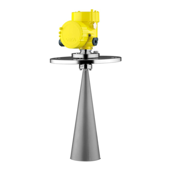
Vega VEGAPULS 68 Quick Setup Manual
Radar sensor for continuous level measurement of bulk solids
Hide thumbs
Also See for VEGAPULS 68:
- Operating instructions manual (105 pages) ,
- Quick setup manual (20 pages) ,
- Product information (20 pages)

Subscribe to Our Youtube Channel
Related Manuals for Vega VEGAPULS 68


Summary of Contents for Vega VEGAPULS 68
- Page 1 Quick setup guide Radar sensor for continuous level measurement of bulk solids VEGAPULS 68 Two-wire 4 … 20 mA/HART Document ID: 47165...
-
Page 2: Table Of Contents
Operating Instructions Manual as well as the Safety Manual that comes with instruments with SIL qualification. These manuals are available on our homepage. Operating instructions VEGAPULS 68 - Two-wire 4 … 20 mA/ HART: Document-ID 36535 Editing status of the quick setup guide: 2021-06-10 VEGAPULS 68 • Two-wire 4 … 20 mA/HART... -
Page 3: For Your Safety
During work on and with the device, the required personal protective equipment must always be worn. Appropriate use VEGAPULS 68 is a sensor for continuous level measurement. You can find detailed information about the area of application in chapter " Product description". Operational reliability is ensured only if the instrument is properly used according to the specifications in the operating instructions manual as well as possible supplementary instructions. -
Page 4: Eu Conformity
This approval is only valid for USA. Hence the following text is only available in the English language. This device complies with Part 15 of the FCC Rules. Operation is subject to the following two conditions: • This device may not cause interference, and VEGAPULS 68 • Two-wire 4 … 20 mA/HART... -
Page 5: Environmental Instructions
That is why we have introduced an environment management system with the goal of continuously improving company environmental pro- tection. The environment management system is certified according to DIN EN ISO 14001. Please help us fulfil this obligation by observing the environmental instructions in this manual: • Chapter " Packaging, transport and storage" • Chapter " Disposal" VEGAPULS 68 • Two-wire 4 … 20 mA/HART... -
Page 6: Product Description
Test certificate (PDF) - optional Move to " www.vega.com" and enter in the search field the serial number of your instrument. Alternatively, you can access the data via your smartphone: • Download the VEGA Tools app from the " Apple App Store" or the " Google Play Store" • Scan the DataMatrix code on the type label of the instrument or • Enter the serial number manually in the app... -
Page 7: Mounting
On the version with rinsing air connection, make sure that the holes in the antenna and in the process fitting coincide. This ensures a suf- ficient air flow (the air is led through the holes to the feed system. A rinsing of the whole parabolic antenna is not intended). Fig. 2: Dismounting, parabolic antenna Connection piece Compression nut Counter nut Parabolic antenna VEGAPULS 68 • Two-wire 4 … 20 mA/HART... -
Page 8: Mounting Preparations
The untwist guards inserted on site must hence be used again. Depending on temperature range and antenna material, these are spring rings according to DIN 217 or wedge lock washers according to DIN 25 201. VEGAPULS 68 • Two-wire 4 … 20 mA/HART... -
Page 9: Mounting Instructions
Fig. 4: Dismounting, parabolic antenna Connection piece Compression nut Counter nut Parabolic antenna Mounting instructions Mounting 1. Distance from the vessel wall > 200 mm, the antenna should protrude > 10 mm into the vessel VEGAPULS 68 • Two-wire 4 … 20 mA/HART... - Page 10 Fig. 5: Distance of the antenna to the vessel wall/vessel ceiling 2. Note min. socket diameter depending on the socket length 3. Note the instructions for sealing For further information see chapter " Mounting". VEGAPULS 68 • Two-wire 4 … 20 mA/HART...
-
Page 11: Connecting To Power Supply
When the screwdriver is released, the terminal closes again. 7. Check the hold of the wires in the terminals by lightly pulling on them 8. Connect the shielding to the internal ground terminal, connect the external ground terminal to potential equalisation VEGAPULS 68 • Two-wire 4 … 20 mA/HART... -
Page 12: Wiring Plan, Single Chamber Housing
Fig. 7: Electronics and connection compartment - single chamber housing Voltage supply, signal output For display and adjustment module or interface adapter For external display and adjustment unit Ground terminal for connection of the cable screening VEGAPULS 68 • Two-wire 4 … 20 mA/HART... -
Page 13: Set Up With The Display And Adjustment Module
The display and adjustment module is powered by the sensor, an ad- ditional connection is not necessary. Fig. 8: Installing the display and adjustment module in the electronics compart- ment of the single chamber housing VEGAPULS 68 • Two-wire 4 … 20 mA/HART... -
Page 14: Parameter Adjustment
2. Select in the menu item " Medium" the medium of your applica- tion, for example " Powder/Dust". 3. Select in the menu item " Application" the vessel, the application and the vessel form, for example, silo. 4. Carry out the adjustment in the menu items " Min. adjustment" and " Max. adjustment". VEGAPULS 68 • Two-wire 4 … 20 mA/HART... - Page 15 In addition, the echo curve of setup can be dis- played in the echo curve window and compared with the current echo curve. The following circumstances cause interfering reflections and can Additional settings - False signal suppression influence the measurement: • High mounting nozzles • Vessel internals such as struts VEGAPULS 68 • Two-wire 4 … 20 mA/HART...
- Page 16 When selecting " Extend", the distance to the medium surface of the created false signal suppression is displayed. This value can now be changed and the false signal suppression can be extended to this range. VEGAPULS 68 • Two-wire 4 … 20 mA/HART...
-
Page 17: Menu Overview
Switched on Diagnostics Menu item Parameter Default setting Device status Peak value indi- Distance cator Electronics tem- Temperature perature Measurement re- liability Simulation Percent Curve display Echo curve False signal sup- pression VEGAPULS 68 • Two-wire 4 … 20 mA/HART... - Page 18 Actual date/Actual time Reset HART mode Address 0 Copy instrument settings - Info Menu item Parameter Device name VEGAPULS 6. Instrument version Hardware and software version Date of manufacture Date Instrument features Order-specific characteristics VEGAPULS 68 • Two-wire 4 … 20 mA/HART...
-
Page 19: Set Up With Smartphone/Tablet, Pc/Notebook Via Bluetooth
1. In the adjustment menu, go to " Additional adjustments", " PIN" Note: The menu item " PIN" is only displayed if in the menu " Setup", " Lock/ Unlock adjustment" the adjustment is released. 2. Change sensor PIN VEGAPULS 68 • Two-wire 4 … 20 mA/HART... -
Page 20: Connecting
Bluetooth-capable instru- ments in the area. PC/Notebook Start PACTware and the VEGA project assistant. Select the device search via Bluetooth and start the search function. The device auto- matically searches for Bluetooth-capable devices in the vicinity. - Page 21 6 Set up with smartphone/tablet, PC/notebook via Bluetooth App view Fig. 12: Example of an app view - Setup sensor adjustment VEGAPULS 68 • Two-wire 4 … 20 mA/HART...
-
Page 22: Supplement
Ʋ for 9.6 V < U < 18 V ≤ 0.7 V (16 … 400 Hz) Ʋ for 18 V < U < 35 V ≤ 1 V (16 … 400 Hz) Load resistor Ʋ Calculation )/0.022 A Ʋ Example - with U = 24 V DC (24 V - 9.6 V)/0.022 A = 655 Ω VEGAPULS 68 • Two-wire 4 … 20 mA/HART... - Page 23 Notes VEGAPULS 68 • Two-wire 4 … 20 mA/HART...
- Page 24 Subject to change without prior notice © VEGA Grieshaber KG, Schiltach/Germany 2021 VEGA Grieshaber KG Am Hohenstein 113 Phone +49 7836 50-0 77761 Schiltach E-mail: info.de@vega.com...
Need help?
Do you have a question about the VEGAPULS 68 and is the answer not in the manual?
Questions and answers