Vega VEGAPULS 67 Quick Setup Manual
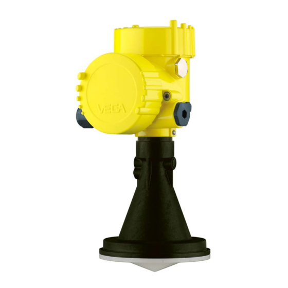
Radar sensor for continuous level measurement of bulk solids
Hide thumbs
Also See for VEGAPULS 67:
- Operating instructions manual (96 pages) ,
- Quick setup manual (24 pages) ,
- Product information (20 pages)

Subscribe to Our Youtube Channel
Related Manuals for Vega VEGAPULS 67


Summary of Contents for Vega VEGAPULS 67
- Page 1 Quick setup guide Radar sensor for continuous level measurement of bulk solids VEGAPULS 67 Four-wire 4 … 20 mA/HART Document ID: 47155...
-
Page 2: Table Of Contents
Operating Instructions Manual as well as the Safety Manual that comes with instruments with SIL qualification. These manuals are available on our homepage. Operating instructions VEGAPULS 67 - Four-wire 4 … 20 mA/ HART: Document-ID 36532 Editing status of the quick setup guide: 2021-06-10 VEGAPULS 67 • Four-wire 4 … 20 mA/HART... -
Page 3: For Your Safety
During work on and with the device, the required personal protective equipment must always be worn. Appropriate use VEGAPULS 67 is a sensor for continuous level measurement. You can find detailed information about the area of application in chapter " Product description". Operational reliability is ensured only if the instrument is properly used according to the specifications in the operating instructions manual as well as possible supplementary instructions. -
Page 4: Eu Conformity
This approval is only valid for USA. Hence the following text is only available in the English language. This device complies with Part 15 of the FCC Rules. Operation is subject to the following two conditions: • This device may not cause interference, and VEGAPULS 67 • Four-wire 4 … 20 mA/HART... -
Page 5: Environmental Instructions
That is why we have introduced an environment management system with the goal of continuously improving company environmental pro- tection. The environment management system is certified according to DIN EN ISO 14001. Please help us fulfil this obligation by observing the environmental instructions in this manual: • Chapter " Packaging, transport and storage" • Chapter " Disposal" VEGAPULS 67 • Four-wire 4 … 20 mA/HART... -
Page 6: Product Description
Test certificate (PDF) - optional Move to " www.vega.com" and enter in the search field the serial number of your instrument. Alternatively, you can access the data via your smartphone: • Download the VEGA Tools app from the " Apple App Store" or the " Google Play Store" • Scan the DataMatrix code on the type label of the instrument or • Enter the serial number manually in the app... -
Page 7: Mounting
Mounting strap The mounting strap enables simple mounting on the vessel wall or silo top. It is suitable for wall, ceiling or boom mounting. Especially in open vessels this is a very easy and effective way to align the sensor to the bulk solid surface. VEGAPULS 67 • Four-wire 4 … 20 mA/HART... - Page 8 – Angle of inclination in three steps 0°, 90° and 180° • Double chamber housing – Angle of inclination 90°, infinitely variable – Angle of inclination in two steps 0° and 90° Fig. 4: Adjustment of the angle of inclination VEGAPULS 67 • Four-wire 4 … 20 mA/HART...
-
Page 9: Mounting Instructions
1. Distance from the vessel wall > 200 mm 200 mm (7.87") Fig. 6: Distance of the antenna to the vessel wall/socket configuration 2. Keep the nozzle short, round off the nozzle end For further information see chapter " Mounting". VEGAPULS 67 • Four-wire 4 … 20 mA/HART... -
Page 10: Connecting To Power Supply
5. Insert the wire ends into the terminals according to the wiring plan Information: Solid cores as well as flexible cores with wire end sleeves are insert- ed directly into the terminal openings. In case of flexible cores without end sleeves, press the terminal from above with a small screwdriver, the terminal opening is then free. When the screwdriver is released, the terminal closes again. VEGAPULS 67 • Four-wire 4 … 20 mA/HART... -
Page 11: Wiring Plan, Double Chamber Housing
Polarity Voltage supply Voltage supply 4 … 20 mA output (active) 4 … 20 mA output (passive) Mass - output Function ground when in- stalling according to CSA (Canadian Standards Asso- ciation) VEGAPULS 67 • Four-wire 4 … 20 mA/HART... - Page 12 Polarity Voltage supply Voltage supply 4 … 20 mA output (active) 4 … 20 mA output (passive) Mass - output Function ground when in- stalling according to CSA (Canadian Standards Asso- ciation) VEGAPULS 67 • Four-wire 4 … 20 mA/HART...
-
Page 13: Set Up With The Display And Adjustment Module
Parameter adjustment Set parameters 1. Go to the menu " Setup" via the display and adjustment module. 2. Select in the menu item " Medium" the medium of your applica- tion, for example " Gravel/Pebble". VEGAPULS 67 • Four-wire 4 … 20 mA/HART... - Page 14 Max. level ≙ min. meas. distance For this adjustment, the distance is entered when the vessel is full and nearly empty. If these values are not known, an adjustment with other distances, for example, 10 % and 90 % is also possible. Starting point for these distance specifications is always the seal surface of the thread or flange. VEGAPULS 67 • Four-wire 4 … 20 mA/HART...
- Page 15 1. Select with [->] the menu item " False signal suppression" and confirm with [OK]. 2. Confirm 3-times with [OK] and enter the actual distance from the sensor to the product surface. 3. All interfering signals in this range are detected by the sensor and stored after being confirmed with [OK]. VEGAPULS 67 • Four-wire 4 … 20 mA/HART...
-
Page 16: Menu Overview
Damping Integration time 0.0 s Current output Output character- 4 … 20 mA mode istics Failure mode ≤ 3.6 mA Current output - Min. current 3.8 mA Min./Max. Max. current 20.5 mA Lock adjustment Released VEGAPULS 67 • Four-wire 4 … 20 mA/HART... - Page 17 Actual date/Actual time Reset HART mode Address 0 Copy instrument settings - Info Menu item Parameter Device name VEGAPULS 6. Instrument version Hardware and software version Date of manufacture Date Instrument features Order-specific characteristics VEGAPULS 67 • Four-wire 4 … 20 mA/HART...
-
Page 18: Set Up With Smartphone/Tablet, Pc/Notebook Via Bluetooth
1. In the adjustment menu, go to " Additional adjustments", " PIN" Note: The menu item " PIN" is only displayed if in the menu " Setup", " Lock/ Unlock adjustment" the adjustment is released. 2. Change sensor PIN VEGAPULS 67 • Four-wire 4 … 20 mA/HART... -
Page 19: Connecting
Bluetooth-capable instru- ments in the area. PC/Notebook Start PACTware and the VEGA project assistant. Select the device search via Bluetooth and start the search function. The device auto- matically searches for Bluetooth-capable devices in the vicinity. - Page 20 6 Set up with smartphone/tablet, PC/notebook via Bluetooth App view Fig. 13: Example of an app view - Setup sensor adjustment VEGAPULS 67 • Four-wire 4 … 20 mA/HART...
-
Page 21: Supplement
Load resistor (4 … 20 mA/HART - passive) Ʋ Calculation )/0.022 A Ʋ Example - U = 24 V DC (24 V - 12 V)/0.022 A = 545 Ω Load resistor (4 … 20 mA/HART - active) < 500 Ω Max. power consumption 4 VA; 2.1 W VEGAPULS 67 • Four-wire 4 … 20 mA/HART... - Page 22 Notes VEGAPULS 67 • Four-wire 4 … 20 mA/HART...
- Page 23 Notes VEGAPULS 67 • Four-wire 4 … 20 mA/HART...
- Page 24 Subject to change without prior notice © VEGA Grieshaber KG, Schiltach/Germany 2021 VEGA Grieshaber KG Am Hohenstein 113 Phone +49 7836 50-0 77761 Schiltach E-mail: info.de@vega.com...
Need help?
Do you have a question about the VEGAPULS 67 and is the answer not in the manual?
Questions and answers