Vega VEGAFLEX 67 Operating Instructions Manual
400 c/160 bar profibus pa level sensor for continuous interface measurement
Hide thumbs
Also See for VEGAFLEX 67:
- Operating instructions manual (64 pages) ,
- Operating instructions manual (57 pages) ,
- Operating instructions manual (64 pages)
Table of Contents
Advertisement
Quick Links
Advertisement
Table of Contents

Related Manuals for Vega VEGAFLEX 67


Summary of Contents for Vega VEGAFLEX 67
-
Page 1: Operating Instructions
Operating Instructions VEGAFLEX 67 400 °C/160 bar Profibus PA... -
Page 2: Table Of Contents
Menu schematic ..... . . 7 Setup with PACTware™ and other adjustment programs Connecting the PC ..... VEGAFLEX 67 - Profibus PA... - Page 3 "Product description. Operating instructions manuals for accessories and replacement parts Tip: To ensure reliable setup and operation of your VEGAFLEX 67, we offer accessories and replacement parts. The associated documents are: Operating instructions manual "External indicating and adjustment unit VEGADIS 61"...
-
Page 4: About This Document
This symbol indicates special instructions for Ex applications. List The dot set in front indicates a list with no implied sequence. à Action This arrow indicates a single action. Sequence Numbers set in front indicate successive steps in a procedure. VEGAFLEX 67 - Profibus PA... -
Page 5: For Your Safety
2.2 Appropriate use VEGAFLEX 67 is a sensor for continuous interface measure- ment in liquids. Detailed information on the application range of VEGAFLEX 67 is available in chapter "Product description". -
Page 6: Fulfilling Namur Recommendations
2.8 Manufacturer declaration In conformity with DIN EN 60079-14/1998, para. 5.2.3, point c1, the probe VEGAFLEX 67 is suitable for use in zone 2. The operator must use the instrument as it was intended to be used and follow the specifications of the following documents:... -
Page 7: Environmental Instructions
The environment man- agement system is certified according to DIN EN ISO 14001. Please help us fulfil this obligation by observing the environ- mental instructions in this manual: Chapter "Storage and transport" VEGAFLEX 67 - Profibus PA... - Page 8 For your safety Chapter "Disposal" VEGAFLEX 67 - Profibus PA...
-
Page 9: Product Description
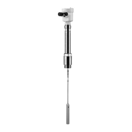
- Supplementary instructions manual "Plug connector for continuously measuring sensors" (optional) - Ex-specific "Safety instructions" (with Ex-versions) - if necessary, further certificates VEGAFLEX 67 consists of the following components: Components Process fitting with probe Housing with electronics Housing cover, optionally available with indicating and adjustment module VEGAFLEX 67 - Profibus PA... -
Page 10: Principle Of Operation
Housing cover with integrated PLICSCOM (optional) Housing with electronics Process fitting 3.2 Principle of operation VEGAFLEX 67 is a level sensor with coax, rod or cable probe Area of application for continuous interface measurment. It is designed for industrial use in all areas of process technology and can be used in liquids. - Page 11 L1 Lower medium L2 Upper medium The interface is directly processed by the sensor and Output signal outputted as digital output signal. The display of PLICSCOM and PACTware™ outputs the distance to the interface (d1) in m(d). VEGAFLEX 67 - Profibus PA...
-
Page 12: Operation
(also available as a download).A CD with the appropriate files can be ordered via e-mail under info@de. vega.com or by phone from one of the VEGA agencies under the order number "DRIVER.S". The backlight of the indicating and adjustment module is powered by the sensor. -
Page 13: Storage And Transport
PE foil is also used. Dispose of the packaging material via specialised recycling companies. Storage and transport temperature see "Supplement - Storage and transport tem- perature Technical data - Ambient conditions" Relative humidity 20 … 85 % VEGAFLEX 67 - Profibus PA... -
Page 14: Mounting
Use the recommended cables (see chapter "Connecting to Moisture power supply") and tighten the cable gland. You can give your VEGAFLEX 67 additional protection against moisture penetration by leading the connection cable down- ward in front of the cable entry. Rain and condensation water can thus drain off. -
Page 15: Mounting Instructions
The max. permissible pressure is stated in chapter "Technical data" in the "Supplement" or on the type label of the sensor. 4.2 Mounting instructions Mount VEGAFLEX 67 in such a way that the probe does not Installation position touch any installations or the vessel wall during installation. - Page 16 Fig. 4: Vessel with conical bottom Make sure that the probe is not subjected to strong lateral Inflowing medium forces. Mount VEGAFLEX 67 at a position in the vessel where no disturbances, e.g. from filling openings, agitators, etc., can occur.
- Page 17 Mounting VEGAFLEX 67 should be integrated in the vessel installation. Heat insulation This prevents the electronics from strong heating by heat radiation. Make sure that in heated vessels the permissible ambient temperature on the housing is not exceeded. The permissible ambient temperature is stated in chapter "Technical data"...
-
Page 18: Connecting To Voltage Supply
Profibus specification. In particular, make sure that the termination of the bus is done with appropriate terminating resistors. On VEGAFLEX 67 with cable gland ½ NPT and plastic Cable gland ½ NPT housing, a metal ½" threaded insert is moulded in the plastic housing. -
Page 19: Connection Steps Instrument Housing
5 Insert the cable into the sensor through the cable entry 6 Lift the opening levers of the terminals with a screwdriver (see following illustration) 7 Insert the wire ends into the open terminals according to the wiring plan VEGAFLEX 67 - Profibus PA... -
Page 20: Wiring Plan, Single Chamber Housing
12 Screw the housing cover back on The electrical connection is finished. 5.3 Wiring plan, single chamber housing The following illustrations apply to the non-Ex as well as to the Ex ia version. VEGAFLEX 67 - Profibus PA... - Page 21 Fig. 9: Electronics and connection compartment, single chamber housing Plug connector for VEGACONNECT (I²C interface) Spring-loaded terminals for connection of the external indication VEGADIS Ground terminal for connection of the cable screen Spring-loaded terminals for voltage supply VEGAFLEX 67 - Profibus PA...
-
Page 22: Wiring Plan, Double Chamber Housing
Blind stopper or plug M12x1 for VEGADIS 61 (option) Housing cover, electronics compartment Filter element for pressure compensation or blind stopper with version IP 66/ IP 68, 1 bar Cable entry or plug Version IP 66/IP 68, 1 bar not with four-wire instruments VEGAFLEX 67 - Profibus PA... - Page 23 Terminals for VEGADIS 61 Connection compartment I 2 C Fig. 13: Connection compartment, double chamber housing Plug connector for VEGACONNECT (I²C interface) Ground terminal for connection of the cable screen Spring-loaded terminals for voltage supply VEGAFLEX 67 - Profibus PA...
-
Page 24: Wiring Plan, Version Ip 66/Ip 68, 1 Bar
Power supply/Signal output 5.5 Wiring plan, version IP 66/IP 68, 1 bar Wire assignment, connection cable Fig. 15: Wire assignment, connection cable brown (+) and blue (-) to power supply or to the processing system Screen VEGAFLEX 67 - Profibus PA... -
Page 25: Setup With The Indicating And Adjustment Module Plicscom
(you can choose any one of four different positions - each displaced by 90°) 3 Press the indicating and adjustment module onto the electronics and turn it to the right until it snaps in. VEGAFLEX 67 - Profibus PA... - Page 26 Fig. 16: Installation of the indicating and adjustment module Note: If you intend to retrofit VEGAFLEX 67 with an indicating and adjustment module for continuous measured value indication, a higher cover with an inspection glass is required.
-
Page 27: Adjustment System
The functions of the individual keys are shown in the above illustration. Approx. 10 minutes after the last pressing of a key, an automatic reset to measured value indication is triggered. Any values not confirmed with [OK] will not be saved. VEGAFLEX 67 - Profibus PA... -
Page 28: Setup Procedure
Setup with the indicating and adjustment module PLICSCOM 6.4 Setup procedure After VEGAFLEX 67 is connected to voltage supply or after Switch-on phase voltage recurrence, the instrument carries out a self-check for approx. 30 seconds. The following steps are carried out: Internal check of the electronics Indication of the instrument type, the firmware as well as... - Page 29 1 Prepare the % value for editing with [OK] and set the cursor to the requested position with [->]. Set the requested percentage value with [+] and save with [OK]. The cursor jumps now to the distance value. VEGAFLEX 67 - Profibus PA...
- Page 30 In general, a period of a few seconds is sufficient to smooth the measured value display. Damping VEGAFLEX 67 - Profibus PA...
- Page 31 A false echo memory should be created with empty vessel so that all potential interfering reflections will be detected. Probes in coax version require no gating out of false echoes since they are not influenced by false reflections. VEGAFLEX 67 - Profibus PA...
- Page 32 The following data are read out or written with this function: Measured value presentation Adjustment Medium Vessel form Damping Linearisation curve Sensor-TAG Displayed value Unit of measurement Language Sensitivity PA scaling unit PV-Out-Scale Channel Additional PA value VEGAFLEX 67 - Profibus PA...
- Page 33 All additional settings are reset to the standard values of the Profibus PA specification. Special parameters All special parameters are reset to delivery status. Pointer The min. and max. values are reset to the actual value. VEGAFLEX 67 - Profibus PA...
- Page 34 Additional adjustment and diagnosis options such as e.g. Optional settings scaling, simulation or trend curve presentation are shown in the following menu schematic. You will find a detailed description of these menu items in the operating instructions manual "Indicating and adjustment module". VEGAFLEX 67 - Profibus PA...
-
Page 35: Menu Schematic
1,000 m(d) 8,000 m(d) 2,000 m(d) Linearisation curve Channel Damping Sensor-TAG linear PV lin. value Sensor Display Basic adjustment ▶ Display Diagnostics Service Info Displayed value Primary Value Diagnostics Basic adjustment Display ▶ Diagnostics Service Info VEGAFLEX 67 - Profibus PA... - Page 36 Info Basic adjustment Display Diagnostics Service ▶ Info Sensor type Date of manufacture Last change using PC Sensor characteristics VEGAFLEX 6x 12. Dec. 2005 Software version Display now? Serial number 3.22 14. December 2005 12345678 VEGAFLEX 67 - Profibus PA...
-
Page 37: Setup With Pactware™ And Other Adjustment Programs
A detailed description is available in the online help of PACTware™ and the VEGA DTMs. Note: Keep in mind that for setup of VEGAFLEX 67, DTM-Collection 10/2005 or a newer version must be used. VEGAFLEX 67 - Profibus PA... -
Page 38: Parameter Adjustment With Pdm
All currently available VEGA DTMs are provided in the DTM Collection on CD and can be obtained from the responsible VEGA agency for a token fee. This CD includes also the up-to- date PACTware™ version. The basic version of this DTM Collection incl. -
Page 39: Maintenance And Fault Rectification
Maintenance and fault rectification 8 Maintenance and fault rectification 8.1 Maintenance When used as directed in normal operation, VEGAFLEX 67 is completely maintenance free. 8.2 Rectify faults VEGAFLEX 67 offers maximum reliability. Nevertheless faults Causes of malfunction can occur during operation. These may be caused by the following, e.g.:... - Page 40 Fault messages via the indi- cating/adjustment module no measured value available à sensor in boot phase à sensor does not find an echo, e.g. because of faulty installation or incorrect parameter adjustment à Wrong sensor length entered VEGAFLEX 67 - Profibus PA...
-
Page 41: Exchange Of The Electronics Module
When loading on site, the order data must be downloaded from the Internet (see Operating Instructions manual "Oscillator"). In both cases, the serial number of VEGAFLEX 67 is required. The serial numbers are stated on the type label of VEGAFLEX 67, on the inner wall of the housing or on the delivery note. -
Page 42: Instrument Repair
The oscillators are adapted to the respective sensor and differ Assignment in their signal output or in their power supply. You can find a suitable oscillator in the following overview. Electronics module FX-E.67P suitable for VEGAFLEX 67 - Profibus PA Profibus PA: FX-E.67PX (X = without approvals) FX-E.67PC (C = approvals XM, CX, CM according to... -
Page 43: Dismounting
Correct disposal avoids negative effects to persons and environment and ensures recycling of useful raw materials. Materials: see "Technical data" If you cannot dispose of the instrument properly, please contact us about disposal methods or return. VEGAFLEX 67 - Profibus PA... -
Page 44: Supplement
- Rod ø 6 mm (0.24 in) approx. 220 g/m (2.4 oz/ft) - Cable ø 4 mm (0.16 in) approx. 80 g/m (0.86 oz/ft) - Gravity weight (optionally only approx. 325 g (11.5 oz) available with cable version) VEGAFLEX 67 - Profibus PA... - Page 45 - Min. dielectric figure (upper me- ε >1,4 dium) - coax version min. dielectric figure - coax version ε >1,4 dead band - coax version - top 30 mm (1.2 in) - bottom 0 mm VEGAFLEX 67 - Profibus PA...
- Page 46 Supplement Fig. 19: Measuring range of VEGAFLEX 67 - coax version Reference plane Probe length Measuring range Upper dead band min. dielectric figure - rod, cable version ε >1,7 dead band - rod version - top 80 mm (3.1 in)
- Page 47 Supplement Fig. 20: Measuring ranges of the VEGAFLEX 67 - rod and cable version Reference plane Probe length Measuring range Upper dead band Lower dead band (only with cable versions) Accuracy (similar to DIN EN 60770-1) Reference conditions according to DIN EN 61298-1 - Temperature +18 …...
- Page 48 Fig. 21: Accuracy - Rod version -110 … +400°C (-166 … +752°F) 10 mm ") 0,15 m 0,5 m (1,6 ft) 32/60 m (105/197 ft) -3 mm (0,5 ft) ") -10 mm ") Fig. 22: Accuracy - Cable version -110 … +400°C (-166 … +752°F) VEGAFLEX 67 - Profibus PA...
- Page 49 60°C (140°F) 0°C (32°F) -110°C 100°C 200°C 300°C 400°C (-166°F) (212°F) (392°F) (572°F) (752°F) -40°C (-40°F) Fig. 24: Ambient temperature - product temperature (version -110 … +400 °C/-166 … +752 °F) Product temperature Ambient temperature VEGAFLEX 67 - Profibus PA...
- Page 50 M20x1.5; plug M12x1 for VEGADIS 61 (optional) 1x closing cap ½ NPT, 1x blind stopper ½ NPT, plug M12x1 for VEGADIS 61 (optional) Depending on the version M12x1, according to DIN 43650, Harting, Am- phenol-Tuchel, 7/8" FF. VEGAFLEX 67 - Profibus PA...
- Page 51 - EEx ia instrument 12 … 30 V DC This function is for instruments with StEx, WHG or ship approval as well as country-specific approvals such as those according to FM or CSA, available at a later date. VEGAFLEX 67 - Profibus PA...
- Page 52 CSA CI.I, Div 2 (NI)+CI.II, III, Div 1 (DIP); CSA CI.I-III, Div 1 (IS); CSA CI.I-III, Div 1 (IS)+Cl.I-III, Div 1 Gr.C-G(XP) Ship approvals Prerequisite for maintaining the protection is a suitable cable. Deviating data in Ex applications: see separate safety instructions. VEGAFLEX 67 - Profibus PA...
-
Page 53: Profibus Pa
GSD file, PNO provides also a general so-called profile-specific GSD file. For VEGAFLEX 67 you have to use the general GSD file „PA139700.GSD“. If the general GSD file is used, the sensor must be set to the profile-specific ident number via the DTM software. - Page 54 PA-Out Select additional cyclic value Fig. 25: VEGAFLEX 67: Block diagram with AI (PA-OUT) value and additional cyclal value TB Transducer Block FB Function Block Module of the PA sensors For the cyclic data traffic, VEGAFLEX 67 provides the following modules:...
- Page 55 The status "Measured value OK" is coded as 80 (hex) (Bit7 = 1, Bit6 … 0 = 0). The measured value is transferred as a 32 bit floating point number in the IEEE-754 format. VEGAFLEX 67 - Profibus PA...
- Page 56 (non-cascade) - active advi- Lo-Alarm sory alarm - low limited 0x8a good (non-cascade) - active advi- Hi-Alarm sory alarm - high limited 0x8d good (non-cascade) - active crit- Lo-Lo-Alarm ical alarm - low limited VEGAFLEX 67 - Profibus PA...
- Page 57 Supplement Status Description according to Profi- Possible cause code bus standard 0x8e good (non-cascade) - active crit- Hi-Hi-Alarm ical alarm - high limited VEGAFLEX 67 - Profibus PA...
-
Page 58: Dimensions
M20x1,5 M20x1,5 M20x1,5/ ½ NPT Fig. 29: Housing versions in protection IP 66/IP 68, 1 bar (with integrated PLICSCOM the housing is 9 mm/0.35 in higher) Stainless steel housing Aluminium double chamber housing Aluminium housing VEGAFLEX 67 - Profibus PA... - Page 59 ø 6 mm ") 12 mm ø 30 mm ") ") ø 54 mm ") Fig. 30: VEGAFLEX 67, cable, rod version with thread (-110 … +400 °C/-166 … +752 °F) Sensor length, see "Technical data" VEGAFLEX 67 - Profibus PA...
- Page 60 VEGAFLEX 67, coax version (-110 … +400 °C/-166 … +752 °F) SW 50 ") G1 / 1”NPT, G1½ / 1½”NPT ø 21,1 mm ") Fig. 31: VEGAFLEX 67, coax version with thread (-110 … +400 °C/-166 … +752 °F) Sensor length, see "Technical data" VEGAFLEX 67 - Profibus PA...
-
Page 61: Industrial Property Rights
Les lignes de produits VEGA sont globalement protégées par des droits de propriété intellectuelle. Pour plus d'informations, on pourra se référer au site http://www.vega.com. VEGA lineas de productos están protegidas por los derechos en el campo de la propiedad industrial. Para mayor información revise la pagina web http://www.vega.com. - Page 62 Supplement VEGAFLEX 67 - Profibus PA...
- Page 63 Supplement VEGAFLEX 67 - Profibus PA...
-
Page 64: Information
All statements concerning scope of delivery, application, practical use and operating conditions of the sensors and processing systems correspond to the information avail- able at the time of printing. © VEGA Grieshaber KG, Schiltach/Germany 2006 Subject to change without prior notice 32768-EN-061227...
Need help?
Do you have a question about the VEGAFLEX 67 and is the answer not in the manual?
Questions and answers