Vega VEGAPULS 68 Operating Instructions Manual
Profibus pa
Hide thumbs
Also See for VEGAPULS 68:
- Operating instructions manual (105 pages) ,
- Quick setup manual (24 pages) ,
- Product information (20 pages)
Table of Contents
Advertisement
Quick Links
Advertisement
Table of Contents

Subscribe to Our Youtube Channel
Related Manuals for Vega VEGAPULS 68


Summary of Contents for Vega VEGAPULS 68
-
Page 1: Operating Instructions
Operating Instructions VEGAPULS 68 Profibus PA... -
Page 2: Table Of Contents
Short description ..... . . Insert the indicating and adjustment module . . . Adjustment system ..... VEGAPULS 68 - Profibus PA... - Page 3 10.4 Industrial property rights....10.5 Trademark ......VEGAPULS 68 - Profibus PA...
-
Page 4: Vegaconnect
Contents Supplementary operating instructions manuals Information: VEGAPULS 68 is available in many versions and is therefore supplied according to customer order. Depending on the selected version, supplementary operating instructions man- uals also come with the delivery. You will find the supple- mentary operating instructions manuals in chapter "Product... -
Page 5: About This Document
This symbol indicates special instructions for Ex applications. List The dot set in front indicates a list with no implied sequence. à Action This arrow indicates a single action. Sequence Numbers set in front indicate successive steps in a procedure. VEGAPULS 68 - Profibus PA... -
Page 6: For Your Safety
2.2 Appropriate use VEGAPULS 68 is a sensor for continuous level measurement. You find detailled specifications on the application range of VEGAPULS 68 in chapter "Product description". -
Page 7: Fulfilling Namur Recommendations
Modifications not expressly approved by VEGA will lead to expiry of the operating licence according to FCC. VEGAPULS 68 is in conformity with part 15 of the FCC regulations. Take note of the respective operating regulations: VEGAPULS 68 - Profibus PA... -
Page 8: Safety Instructions For Ex Areas
2.9 Manufacturer declaration In conformity with DIN EN 60079-14/2004, para. 5.2.3, point c1, VEGAPULS 68 is suitable for use in zone 2. The operator must use the instrument as it was intended to be used and follow the specifications of the following documents:... -
Page 9: Functional Range Of Approved Instruments
The environment man- agement system is certified according to DIN EN ISO 14001. Please help us fulfil this obligation by observing the environ- mental instructions in this manual: Chapter "Storage and transport" Chapter "Disposal" VEGAPULS 68 - Profibus PA... -
Page 10: Product Description
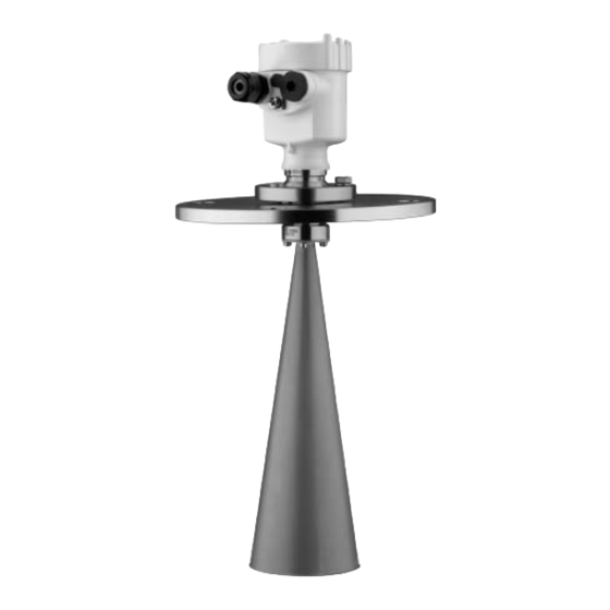
- Supplementary instructions manual "Plug connector for continuously measuring sensors" (optional) - Ex-specific "Safety instructions" (with Ex-versions) - if necessary, further certificates VEGAPULS 68 consists of the following components: Components Horn or parabolic antenna process fitting (depending on the version flange or thread) Optionally available with swivelling holder (only with flange), rinsing air connection, reflux valve... -
Page 11: Principle Of Operation
VEGAPULS 68 is a radar sensor in K-band technology for Area of application continuous level measurement of solids. A version of VEGAPULS 68 is available for each area of application: The version with horn antenna is particularly suitable for measurement of virtually all bulk solids in small silos and vessels. -
Page 12: Operation
(also available as a download).A CD with the appropriate files can be ordered via e-mail under info@de. vega.com or by phone from one of the VEGA agencies under the order number "DRIVER.S". The backlight of the indicating and adjustment module is powered by the sensor. -
Page 13: Storage And Transport
PE foil is also used. Dispose of the packaging material via specialised recycling companies. Storage and transport temperature see "Supplement - Storage and transport tem- perature Technical data - Ambient conditions" Relative humidity 20 … 85 % VEGAPULS 68 - Profibus PA... -
Page 14: Mount
Use the recommended cables (see chapter "Connecting to Moisture power supply") and tighten the cable gland. You can give your VEGAPULS 68 additional protection against moisture penetration by leading the connection cable down- ward in front of the cable entry. Rain and condensation water can thus drain off. -
Page 15: Mounting Preparations - Horn Antenna
Information: If the medium reaches the antenna, buildup can form on it and cause faulty measurements later on. Make sure that the wetted parts of VEGAPULS 68, especially Wetted materials the seal and process fitting, are suitable for the existing process conditions such as pressure, temperature etc. -
Page 16: Mounting Preparations - Parabolic Antenna
4.3 Mounting preparations - Parabolic antenna Information: This information applies only to special versions! VEGAPULS 68 is also available in versions where the antenna has a bigger diameter than the process fitting (thread, flange). The antenna must therefore be disconnected from the flange before mounting. - Page 17 Mount 1 Clamp VEGAPULS 68 with the flange, e.g. in a bench vice 2 Hold the connection piece (3) with a wrench SW 22 on the flattenings 3 Unscrew the locknut (2) with SW 36 against the antenna 4 Unscrew the compression nut (1) with a wrench SW 41...
-
Page 18: Mounting Instructions
Mount 4.4 Mounting instructions The illustrations in the mounting instructions show a VEGA- Horn and parabolic antenna PULS 68 with horn antenna. The mounting instructions also apply to VEGAPULS 68 with parabolic antenna. Mount the sensor at 200 mm (7.874 in) away from the vessel Installation position wall. - Page 19 If mounting in the center of the silo is not possible, the sensor can be directed to the vessel center by means of an optional swivelling holder. The following description gives an overview on the determination of the necessary angle of inclination. VEGAPULS 68 - Profibus PA...
- Page 20 Mount Fig. 8: Proposal for installation after orientation VEGAPULS 68 The angle of inclination depends on the vessel dimensions. It can be checked easily on the sensor with a suitable level or air-lever. The following chart states the distance "a" between installation position and vessel center depending on the measuring distance for an angle of inclination of 2°...
- Page 21 The optimum mounting position is on the opposite of the filling. To avoid strong pollution, the distance to the filter or dust extraction must be as big as possible. VEGAPULS 68 - Profibus PA...
- Page 22 Fig. 10: Recommended socket mounting If the reflective properties of the medium are good, you can mount VEGAPULS 68 on sockets which are higher than the length of the antenna. You will find recommended values for socket heights in the following illustration. The socket end should be smooth and burr-free, if possible also rounded.
- Page 23 150 mm/6" 800 mm Fig. 11: Deviating socket dimensions Tip: VEGAPULS 68 is optionally also available with antenna extension. Hence the antenna length can be selected such that the antenna end protrudes 10 mm (0.4 in) out of the socket.
- Page 24 Mount Fig. 12: Installation of VEGAPULS 68 in multiple chamber silos Fig. 13: Orientation of VEGAPULS 68 for emptying in the silo center Silo installations such as e.g. ladders, level switches, struts, Vessel installations and also structured vessel walls, can cause false echoes that get superimposed on the useful echo.
- Page 25 Tip: In case of extreme dust in the antenna system, VEGAPULS 68 is available with purging connection e.g. for air. The air is distributed via channels in the antenna system and keeps is virtually clean from dust.
- Page 26 Keep in mind that for these applications, the sensors are designed for relatively slow level changes. When using VEGAPULS 68 on a movable bracket, the max. measuring rate must be observed (see chapter "Technical data"). VEGAPULS 68 - Profibus PA...
-
Page 27: Connecting To Voltage Supply
Profibus specification. In particular, make sure that the termination of the bus is done with appropriate terminating resistors. On VEGAPULS 68 with cable gland ½ NPT and plastic Cable gland ½ NPT housing, a metal ½" threaded insert is moulded in the plastic housing. -
Page 28: Connection Steps - Instrument Housing
5 Insert the cable into the sensor through the cable entry 6 Lift the opening levers of the terminals with a screwdriver (see following illustration) 7 Insert the wire ends into the open terminals according to the wiring plan VEGAPULS 68 - Profibus PA... -
Page 29: Wiring Plan, Single Chamber Housing
12 Screw the housing cover back on The electrical connection is finished. 5.3 Wiring plan, single chamber housing The following illustrations apply to the non-Ex as well as to the Ex ia version. VEGAPULS 68 - Profibus PA... - Page 30 Fig. 20: Electronics and connection compartment, single chamber housing Plug connector for VEGACONNECT (I²C interface) Spring-loaded terminals for connection of the external indication VEGADIS Ground terminal for connection of the cable screen Spring-loaded terminals for voltage supply VEGAPULS 68 - Profibus PA...
-
Page 31: Wiring Plan, Double Chamber Housing
Blind stopper or plug M12x1 for VEGADIS 61 (option) Housing cover, electronics compartment Filter element for pressure compensation or blind stopper with version IP 66/ IP 68, 1 bar Cable entry or plug Version IP 66/IP 68, 1 bar not with four-wire instruments VEGAPULS 68 - Profibus PA... - Page 32 Terminals for VEGADIS 61 Connection compartment I ² C Fig. 24: Connection compartment, double chamber housing Plug connector for VEGACONNECT (I²C interface) Ground terminal for connection of the cable screen Spring-loaded terminals for voltage supply VEGAPULS 68 - Profibus PA...
-
Page 33: Wiring Plan, Double Chamber Housing Exd
Blind stopper or plug M12x1 for VEGADIS 61 (option) Housing cover, electronics compartment Filter element for pressure compensation or blind stopper with version IP 66/ IP 68, 1 bar Cable entry or plug Version IP 66/IP 68, 1 bar not with four-wire instruments VEGAPULS 68 - Profibus PA... - Page 34 Internal connection cable to the connection compartment Terminals for VEGADIS 61 Connection compartment Fig. 28: Connection compartment, double chamber housing Exd Spring-loaded terminals for power supply and cable screen Ground terminal for connection of the cable screen VEGAPULS 68 - Profibus PA...
-
Page 35: Wiring Plan, Version Ip 66/Ip 68, 1 Bar
(+) and blue (-) to power supply or to the processing system Screen 5.7 Switch-on phase After VEGAPULS 68 is connected to voltage supply or after Switch-on phase voltage recurrence, the instrument carries out a self-check for approx. 30 seconds. The following steps are carried out: Internal check of the electronics Indication of the instrument type, the firmware as well as... -
Page 36: Set Up With The Indicating And Adjustment Module Plicscom
- each displaced by 90°) 3 Press the indicating and adjustment module onto the electronics and turn it to the right until it snaps in. 4 Screw housing cover with inspection window tightly back VEGAPULS 68 - Profibus PA... - Page 37 Fig. 31: Installation of the indicating and adjustment module Note: If you intend to retrofit VEGAPULS 68 with an indicating and adjustment module for continuous measured value indication, a higher cover with an inspection glass is required.
-
Page 38: Adjustment System
The functions of the individual keys are shown in the above illustration. Approx. 10 minutes after the last pressing of a key, an automatic reset to measured value indication is triggered. Any values not confirmed with [OK] will not be saved. VEGAPULS 68 - Profibus PA... -
Page 39: Setup Procedure
find a detailed description in the operating instructions manual of the indicating and adjustment module or in the online help of PACTware™ or DTM. As VEGAPULS 68 is a distance measuring instrument, the Parameter adjustment distance from the sensor to the product surface is measured. - Page 40 Medium Solid With solids, you can also choose between "Powder/Dust", "Granular/Pellets" or "Ballast/Pebbels". VEGAPULS 68 - Profibus PA...
- Page 41 Gating out of false signals chapter "Mounting", can influence the measurement. A gating our of false echoes detects, marks and saves these false signals so that they are no longer taken into account for level VEGAPULS 68 - Profibus PA...
- Page 42 The menu item "Extended setting" offers the possibility to Extended setting/Quick level change optimise VEGAPULS 68 for applications with quick level changes. For this purpose select the function "Quick level change >1 m/min.". Extended setting None...
- Page 43 Reset If the "Reset" is carried out, the sensor resets the values of the following functions to the reset values (see chart): Function Reset value Max. adjustment 0 m(d) With standpipe versions. Sensor-specific basic adjustment. VEGAPULS 68 - Profibus PA...
- Page 44 You will find a detailed description of these menu items in the operating instructions manual "Indicating and adjustment module". Special parameters are parameters which are set customer-specifically on the service level with the adjustment software PACTware™. VEGAPULS 68 - Profibus PA...
-
Page 45: Menu Schematic
10.000 m(d) 0,000 m(d) 1.245 m(d) 6.789 m(d) Vessel form Linearisation curve Channel Damping Silo linear PV lin. value Sensor-TAG Sensor Display Basic adjustment ▶ Display Diagnostics Service Info Displayed value Lighting ▼ PA-Out Switched off VEGAPULS 68 - Profibus PA... - Page 46 Info Basic adjustment Display Diagnostics Service ▶ Info Sensor type Date of manufacture Last change using PC Sensor characteristics VEGAPULS 6x 19. February 2007 Software version Display now? Serial number 3.50 19. February 2007 12345678 VEGAPULS 68 - Profibus PA...
-
Page 47: Saving The Parameter Adjustment Data
They are hence available for multiple use or service purposes. If VEGAPULS 68 is equipped with an indicating and adjust- ment module, the most important data can be read out of the sensor into indicating and adjustment module. The procedure is described in the operating instructions manual "Indicating... -
Page 48: Setup With Pactware™ And Other Adjustment Programs
A detailed description is available in the online help of PACTware™ and the VEGA DTMs. Note: Keep in mind that for setup of VEGAPULS 68, the current version of the DTM Collection must be used. VEGAPULS 68 - Profibus PA... -
Page 49: Parameter Adjustment With Pdm
All currently available VEGA DTMs are provided in the DTM Collection on CD and can be obtained from the responsible VEGA agency for a token fee. This CD includes also the up-to- date PACTware™ version. The basic version of this DTM Collection incl. -
Page 50: Maintenance And Fault Rectification
Maintenance and fault rectification 8 Maintenance and fault rectification 8.1 Maintenance When used as directed in normal operation, VEGAPULS 68 is completely maintenance free. In some applications, builup on the antenna system can influence the measuring result. Depending on the sensor and application, make arrangements to avoid strong pollution of the antenna system. - Page 51 Check and correct, if necessary In Ex applications, the regulations for the wiring of intrinsically safe circuits must be observed. E013 Fault messages via the indi- cating/adjustment module no measured value available à sensor in boot phase VEGAPULS 68 - Profibus PA...
-
Page 52: Exchange Of The Electronics Module
Ex approval may be used. If there is no electronics module available on site, one can be ordered from the VEGA agency serving you. The order data of the sensor must be downloaded into the new Sensor serial number electronics module. -
Page 53: Instrument Repair
Oscillator PS-E.60SP is suitable for VEGAPULS 67 and 68 - Profibus PA Profibus PA: PS-E.60SPX (X = without approvals) PS-E.60SPD (D = approvals KX, KF according to VEGA product list) PS-E.60SPE (E = approvals CX, DX, CK, DK, GX, GI, XM, CM, UX, UF according to VEGA product list) 8.4 Instrument repair... -
Page 54: Dismounting
Correct disposal avoids negative effects to persons and environment and ensures recycling of useful raw materials. Materials: see chapter "Technical data" If you cannot dispose of the instrument properly, please contact us about disposal methods or return. VEGAPULS 68 - Profibus PA... -
Page 55: Supplement
5 … 16.2 kg (11 … 35.7 lbs), depending on the flange size and housing - Process fitting swivelling holder with 6 … 17.2 kg (13.2 … 37.9 lbs), depending on flange the flange size and housing VEGAPULS 68 - Profibus PA... - Page 56 - ø 40 mm (1.575 in) 22° - ø 48 mm (1.89 in) 18° - ø 75 mm (2.953 in) 10° - ø 95 mm (3.74 in) 8° - Beam angle 3 dB with parabolic 4° antenna VEGAPULS 68 - Profibus PA...
- Page 57 70 m -15 mm -30 mm Fig. 34: Accuracy VEGAPULS 68 with horn antenna in mm, measuring range in m Time to output the correct level (with max. 10 % deviation) after a sudden level change. Incl. non-linearity, hysteresis and non-repeatability.
- Page 58 1.180 in 0.590 in 3.280 ft 229.7 ft - 0.590 in - 1.180 in Fig. 35: Accuracy VEGAPULS 68 with horn antenna in Inch, measuring range in ft 40 mm 15 mm 2,0 m 70 m -15 mm -40 mm Fig.
-
Page 59: Cording To Din-En-Asme-Jis
4 g and 5 … 100 Hz Data on rinsing air connection Pressure max. 6 bar (87.02 psi) Relating to the nominal measuring range. Tested according to the regulations of German Lloyd, GL directive 2 VEGAPULS 68 - Profibus PA... - Page 60 Reflux valve - attached (with non-Ex option, with Ex in the scope of delivery) - Material 316Ti - Seal FKM (Viton), Kalrez - for tube diameter 6 mm - opening pressure 0.5 bar (7.25 psi) - Nominal pressure stage PN 250 VEGAPULS 68 - Profibus PA...
- Page 61 0.5 mm² - wire resistance <0.036 Ohm/m - Tensile strength >1200 N (270 lbf) - Standard length 5 m (16.4 ft) Depending on the version M12x1, according to DIN 43650, Harting, Am- phenol-Tuchel, 7/8" FF. VEGAPULS 68 - Profibus PA...
- Page 62 - EEx ia instrument 12 … 24 V DC Power supply by/max. number of sensors - DP/PA segment coupler max. 32 (max. 10 with Ex) - VEGALOG 571 EP card max. 15 (max. 10 with Ex) VEGAPULS 68 - Profibus PA...
- Page 63 (XP-IS) CL I, II, III, DIV1, GP ABCDEFG Ship approvals GL, LRS, ABS, CCS, RINA Prerequisite for maintaining the protection is a suitable cable. Deviating data in Ex applications: see separate safety instructions. Depending on order specification. VEGAPULS 68 - Profibus PA...
-
Page 64: Profibus Pa
GSD file, PNO provides also a general so-called profile-specific GSD file. For VEGAPULS 68 you have to use the general GSD file „PA139700.GSD“. If the general GSD file is used, the sensor must be set to the profile-specific ident number via the DTM software. - Page 65 PA-Out Select additional cyclic value Fig. 39: VEGAPULS 68: Block diagram with AI (PA-OUT) value and additional cyclical value TB Transducer Block FB Function Block Module of the PA sensors For the cyclic data traffic, VEGAPULS 68 provides the following modules:...
- Page 66 The status "Measured value OK" is coded as 80 (hex) (Bit7 = 1, Bit6 … 0 = 0). The measured value is transferred as a 32 bit floating point number in the IEEE-754 format. VEGAPULS 68 - Profibus PA...
- Page 67 (non-cascade) - active advi- Lo-Alarm sory alarm - low limited 0x8a good (non-cascade) - active advi- Hi-Alarm sory alarm - high limited 0x8d good (non-cascade) - active crit- Lo-Lo-Alarm ical alarm - low limited VEGAPULS 68 - Profibus PA...
- Page 68 Supplement Status Description according to Profi- Possible cause code bus standard 0x8e good (non-cascade) - active crit- Hi-Hi-Alarm ical alarm - high limited VEGAPULS 68 - Profibus PA...
-
Page 69: Dimensions
") M16x1,5 M20x1,5 M20x1,5 M20x1,5 M20x1,5/ ½ NPT Fig. 43: Housing versions in protection IP 68 (with integrated PLICSCOM the housing is 9 mm/0.35 in higher) Stainless steel housing Aluminium double chamber housing Aluminium housing VEGAPULS 68 - Profibus PA... - Page 70 ø48 3" ø75 4" ø95 inch " ø1 " 1½" " ø1 " 2" " ø2 " 3" " ø3 " 4" Fig. 44: VEGAPULS 68, horn antenna in threaded version Standard with temperature adapter VEGAPULS 68 - Profibus PA...
- Page 71 4" " ø3 " Fig. 45: VEGAPULS 68, horn antenna in threaded version with purging air connection Standard with temperature adapter Purging air connection G⅛ A for mounting of a suitable adapter Reflux valve - attached (with non-Ex optionally available, with Ex in the scope of delivery), for tube diameters 6 mm...
- Page 72 " ø3 " 4" Fig. 46: VEGAPULS 68, horn antenna in threaded version with antenna extension Standard with temperature adapter Depending on the product properties, an antenna extension causes a re- duction of the sensitivity in the narrow range. Depending on the length, a suitable support of the antenna extensions must be provided.
- Page 73 " 8xø " " " " 6" 150 lb 279,4 25,4 241,3 8xø22,4 6" 150 lb 11" 1" " 8xø " " Fig. 47: VEGAPULS 68, horn antenna in flange version Standard with temperature adapter VEGAPULS 68 - Profibus PA...
- Page 74 8xø " " " Fig. 48: VEGAPULS 68, horn antenna in flange version with purging air connection Standard with temperature adapter Purging air connection G⅛ A for mounting of a suitable adapter Reflux valve - attached (with non-Ex optionally available, with Ex in the scope of delivery), for tube diameters 6 mm...
- Page 75 DN 80 / 3" " " " 4xø " " " " 8xø " DN 100 / 4" 11,5 182,5 4xø22 DN 100 / 4" Fig. 49: VEGAPULS 68, horn antenna and swivelling holder Standard with temperature adapter VEGAPULS 68 - Profibus PA...
- Page 76 " DN 100 / 4" Fig. 50: VEGAPULS 68, horn antenna, swivelling holder and rinsing air connection Purging air connection G⅛ A for mounting of a suitable adapter Reflux valve - attached (with non-Ex optionally available, with Ex in the scope of delivery), for tube diameters 6 mm...
- Page 77 Supplement VEGAPULS 68, parabolic antenna in threaded version 46mm ") G1½A / 1½ NPT ø 244mm (9 ") Fig. 51: VEGAPULS 68, parabolic antenna in threaded version Standard with temperature adapter VEGAPULS 68 - Profibus PA...
- Page 78 228,6 23,9 190,5 8xø19,1 4" 150 lb 6" 150 lb 279,4 25,4 241,3 8xø22,4 6" 150 lb 11" 1" " 8xø " Fig. 52: VEGAPULS 68, parabolic antenna in flange version Standard with temperature adapter VEGAPULS 68 - Profibus PA...
- Page 79 156,2 4xø21 DN 80 / 3" " " " 8xø " DN 100 / 4" 11,5 182,5 4xø22 DN 100 / 4" Fig. 53: VEGAPULS 68, parabolic antenna and swivelling holder Standard with temperature adapter VEGAPULS 68 - Profibus PA...
- Page 80 " " 8xø " Fig. 54: VEGAPULS 68, parabolic antenna and swivelling holder with purging air connection Standard with temperature adapter Purging air connection G⅛ A for mounting of a suitable adapter Reflux valve - attached (with non-Ex optionally available, with Ex in the scope of delivery), for tube diameters 6 mm...
-
Page 81: Industrial Property Rights
Les lignes de produits VEGA sont globalement protégées par des droits de propriété intellectuelle. Pour plus d'informations, on pourra se référer au site http://www.vega.com. VEGA lineas de productos están protegidas por los derechos en el campo de la propiedad industrial. Para mayor información revise la pagina web http://www.vega.com. - Page 82 Supplement VEGAPULS 68 - Profibus PA...
- Page 83 Supplement VEGAPULS 68 - Profibus PA...
- Page 84 All statements concerning scope of delivery, application, practical use and operating conditions of the sensors and processing systems correspond to the information avail- able at the time of printing. © VEGA Grieshaber KG, Schiltach/Germany 2007 Subject to change without prior notice 29263-EN-070305...
Need help?
Do you have a question about the VEGAPULS 68 and is the answer not in the manual?
Questions and answers